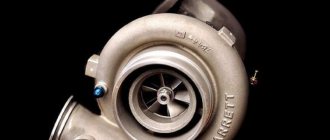
Owners of turbo engines often wonder about the need to cool the turbine before turning off the engine. Such cooling requires several minutes of idling of the internal combustion engine. To get an accurate answer, you need to find out under what conditions the engine turbocharger operates. Exhaust gases contain a large amount of useful energy, which is obtained as a result of combustion of fuel in the cylinders. Redirecting the exhaust flow to the turbine wheel allows for efficient drive for the compressor. In this way, it is possible to obtain air injection under pressure without taking power from the internal combustion engine, which fundamentally distinguishes a turbocharger from a mechanical supercharger.
We also recommend reading the article on how to check a diesel engine turbine yourself. In this article you will learn about various ways to diagnose a supercharger yourself.
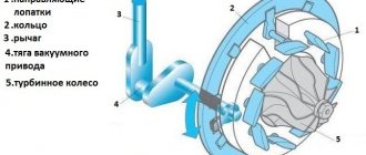
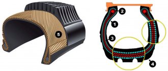
The turbocharger is an axle at the ends of which there are wheels with blades. There are turbine and compressor wheels. These wheels are located in special housings. The supercharger is placed in the exhaust tract, since the turbine wheel rotates from contact with the exhaust gases. This rotation allows the compressor wheel to rotate in parallel, sucking in and compressing air to supply it to the engine cylinders.
Turbine repair in Moscow
Repairing a diesel engine turbine in a car is a rather complex technical process that requires a specialist to have professional skills and extensive experience in this matter, as well as the use of special computer equipment to perform checks.
repairing a diesel engine turbine with your own hands , even if you are confident in your own professional skills. The desire to save money never ends well. Repairs require special tools, equipment and skills, especially. Remember that the miser pays twice. Contact specialists, only there you can get qualified and professional help at reasonable prices.
Characteristics of the main parameters of nominal values
- The rated power of the turbine
is the maximum power that the turbine must develop for a long time at the terminals of the electric generator, at normal values of the main parameters or when they change within the limits specified by industry and state standards. A turbine with controlled steam extraction can develop power above its rated value if this meets the strength conditions of its parts. - The economic power of a turbine
is the power at which the turbine operates most economically. Depending on the parameters of the fresh steam and the purpose of the turbine, the rated power can be equal to or greater than the economic power by 10-25%. - The nominal temperature of regenerative heating of feed water
is the temperature of the feed water downstream of the last heater along the water flow. - Nominal cooling water temperature
is the temperature of the cooling water entering the condenser.
Steam turbine of ZuGRES. USSR, 1930s
Reasons for turbine failure
If you notice the first signs of a unit malfunction, do not rush to run to the store to buy a new turbocharger for your car. You must first find out the source of the problem , and as practice shows, most often these are external factors. Mainly incorrect operation or untimely maintenance. However, if the problems are not corrected, this will lead to failure of the new or restored unit. The turbine rarely fails due to its spent life.
Causes of turbocharger failure:
- Late service
- Poor oil quality
- Oil fasting
- Debris getting inside the unit or impeller
- Regular increased loads and overheating
Late service
Ignoring the timing of changing engine oil and filters usually leads to problems. The oil needs to be changed more often than necessary. The diesel engine turbine does not like long intervals between oil changes. Optimally, this is no more than 10 thousand km , however, if the car is constantly operated in an urban environment where there is a lot of dust, it is better to reduce the interval by 15-20%.
Poor quality oil
Poor quality oil, as well as the presence of foreign particles in it, usually causes the formation of scoring on the surface of the bearings.
Where does the garbage come from:
- Metal particles resulting from damage to the bearing unit;
- Poor quality motor oil;
- Clogged oil filter;
- After poor quality engine repair.
Oil fasting
A serious problem that often leads to problems with the diesel engine turbine. Even a slight lack of lubrication for a couple of seconds leads to severe damage to the bearings of the unit. This phenomenon occurs due to the fault of the car owners themselves.
Remember that before turning off the car engine after a long trip, let it idle for 1-2 minutes to cool down.
Why is this necessary? This is necessary in order for the unit to cool down; its rotation speed can reach 180 thousand rpm. in a minute . And turning off the engine, the oil pressure will instantly drop, and the unit will be left without lubrication for a couple of seconds. Diesel engine turbine repair
Damage
Damage due to debris and foreign objects getting inside the unit. They are clearly visible upon visual inspection, on the wheel of the unit. Any solid particles that are not even visible to the eye damage the turbocharger rotor.
The entry of foreign particles into the scroll or housing causes destruction of the rotor blades. It should not work with such damage under any circumstances.
Engine turbine overheating
Excessive loads on it lead to strong heating, and ultimately overheating. Temperatures under load can reach 900 degrees . Overheating can also occur as a result of insufficient cooling of the unit due to constant, frequent engine switching on and off. All this leads to carbon deposits on the turbocharger and in the oil pipes, increased wear of the bearing from the assembly and sealing rings.
The operating condition of a car's diesel engine directly affects the health of the unit.
Diesel turbine problems
As practice shows, in cars with a diesel engine the unit fails most often for two reasons:
- Poor quality oil;
- Lack of oil.
Diesel engines often barely warm up when operating in the city, because do not have time to warm up, especially in winter. And numerous engine starts lead to the rotor rotating with virtually no lubrication. Especially if the car owner does not comply with or delays the replacement of engine oil and filters. As a result, the first signs of unit malfunctions may appear at 100-150 thousand km. mileage
Remember that increasing friction leads to severe wear and serious problems in the operation of the diesel engine turbine. In this case, repairs will definitely be needed. This is why it is important to know the source of the problem and when repair work is needed.
Turbojet engine turbine cooling system
The turbine cooling system of a turbojet engine contains a sequentially installed manifold with controlled valves at the outlet, connected by its inlet with the air cavity of the combustion chamber, a multi-channel air duct passing through the internal cavities of the nozzle blades, a nozzle swirl apparatus and impeller cooling channels. For a dual-circuit turbojet engine, the cooling system is equipped with an air-to-air heat exchanger located in the air path of the external circuit. The connection between the collector and the air cavity of the combustion chamber is made through the cooled channels of the heat exchanger. An additional collector is installed between the collector outlet and the multi-channel air duct. Each air duct channel is formed by a deflector installed in the nozzle blade along its inner surface. The outlet channel of the swirl nozzle apparatus is turned in the direction of rotation of the impeller, and the center line of this wheel forms an angle with the longitudinal axis of the engine in the range of 60-85o. The invention makes it possible to reduce the temperature of the turbine impeller and the associated reduction in the radial clearance between the stator and the impeller. 2 salary f-ly, 5 ill.
The invention relates to the field of aircraft engine manufacturing, namely to cooling systems for turbojet turbines.
A turbojet engine cooling system is known [1]. Of the known cooling systems, the closest to the proposed one is the turbojet turbine cooling system, which contains a sequentially installed manifold with controlled valves at the outlet, connected by its inlet with the air cavity of the combustion chamber, a multi-channel air duct passing through the internal cavities of the nozzles blades, nozzle swirl apparatus and impeller cooling channels [2]. In this system, the turbine elements are cooled by air taken from the last stage of the compressor, which has the highest temperature level in the gas-air path of the engine. This air is supplied to cool the rotor blades through the impeller disk in its middle and peripheral zones. On the other hand, heat is supplied to the disk from the gas-air path of the turbine through the working blades and their locking part. The high temperature of the cooling air leads to an increase in the temperature of the peripheral and middle zones with a relatively “cold” disk hub. Such uneven temperatures in the disk leads to a high level of stress in it, which reduces the engine life at maximum conditions. In addition, the high temperature of the impeller elements leads to their significant thermal expansion, as a result of which the radial clearance between the stator and the impeller increases. The objective of the invention is to reduce the temperature of the turbine impeller and the associated reduction in the radial clearance between the stator and the impeller. In the single-circuit engine design, it is not possible to reduce the temperature of the air supplied to cool the turbine impeller, although there is a sufficient pressure margin. The presence of a swirling apparatus makes it possible to partially reduce the temperature of the air supplied to the impeller in the case when the air is exhausted in the direction of rotation of the impeller. To a greater extent, a decrease in temperature without the use of an additional working fluid can be achieved in the circuit of widely used bypass turbojet engines. This problem is solved by the fact that the known cooling system of a turbojet engine turbine, containing a sequentially installed manifold with controlled valves at the outlet, connected by its inlet with the air cavity of the chamber combustion, multi-channel air duct passing through the internal cavities of the nozzle blades, nozzle swirl apparatus and cooling channels of the impeller; for a bypass turbojet engine, it is equipped with an air-to-air heat exchanger located in the air path of the outer circuit; the connection of the manifold with the air cavity of the combustion chamber is made through the cooled channels of the heat exchanger , an additional collector is installed between the outlet of the manifold and the multi-channel air duct, with each channel of the air duct formed by a deflector installed in the nozzle blade along its inner surface, and the outlet channel of the nozzle swirl apparatus is turned in the direction of rotation of the impeller, and the middle line of this channel forms with the longitudinal axis engine angle in the range of 6085o. In this case, the heat exchanger is made in the form of separate sections, evenly distributed along the perimeter of the outer circuit of the engine. The deflector can be made perforated, and the cavity formed by the deflector and the inner surface of the nozzle blade is connected to the gas-air path of the turbine through a slot in the trailing edge. The presence of a heat exchanger located in the outer circuit, the inlet of which is connected via a cooled path to the air cavity of the combustion chamber, and the outlet - with an air duct, allows you to significantly reduce the temperature of the cooling air. Making the air duct in the form of a deflector installed in the nozzle blade along its inner surface leads, on the one hand, to a reduction in pressure losses of the cooling air, which partially compensates for the pressure losses in the heat exchanger, and on the other reduces the heating of transit air from the nozzle blades. As a result, we have minimal pressure losses in the cooling tract with a significant decrease in the temperature of the cooling air supplied to the swirling apparatus. The high pressure of air supplied to the twisting apparatus ensures a high speed of this air in its outlet channels, which leads to an additional decrease in its temperature. In this case, the maximum temperature reduction is realized in the case of air supply in the direction of rotation of the impeller in the angular range of 6085o. Figure 1 shows a longitudinal section of an engine with a cooling system; Fig. 2 is a cross-section of a nozzle blade with a deflector; in fig. 3 — cross-section of a nozzle blade with a perforated deflector; Fig.4 is a cross-section of the swirl nozzle apparatus and the impeller; Fig. 5 is a view along arrow C on the heat exchanger section. The cooling system of the turbojet engine contains a manifold 1 with controlled valves 2, an air cavity 3 of the combustion chamber 4, a multi-channel air duct 5 passing through the internal cavities 6 of the nozzle blades 7, a swirl nozzle apparatus 8, channels cooling 9 impeller 10 turbine. The cooling system is equipped with an air-to-air heat exchanger 11 located in the air path 12 of the external circuit 13. The connection of the manifold 1 with the air cavity 3 of the combustion chamber 4 is made through the cooled channels 14 of the heat exchanger 11, and an additional manifold 15 is installed between the outlet of the manifold 1 and the multi-channel air duct 5, Moreover, each channel 16 of the air duct 5 is formed by a deflector 17 installed in the nozzle blade 7 along its inner surface 18. The output channel 19 of the nozzle swirl apparatus 8 is turned in the direction of rotation of the impeller 10, and the center line 20 of the channel 19 forms an angle with the longitudinal axis 21 of the engine in the range of 6085o. The swirl nozzle apparatus 8 and the impeller 10 form the front duct cavity 22 of the turbine. The impeller contains cooling channels 9 and a working blade 23, the end 24 of which is separated from the stator 25 by a radial gap 26. The heat exchanger 11 is made in the form of separate sections 27, evenly distributed along the perimeter 28 of the outer circuit 13. For high-temperature turbojet engines, the deflector 17 is made with perforated holes 29, and the cavity 30 formed by the deflector 17 and the inner surface 18 of the nozzle blade 7 is connected through a slot 31 in the trailing edge 32 with the gas-air path 33 of the turbine. The cooling system of the turbojet engine operates as follows. Air from the air cavity 3 of the combustion chamber 4 enters the cooled channels 14 of the heat exchanger 11 , where it is cooled by the colder air of the air path 12 of the external circuit 13. After cooling, the air enters the manifold 1 along the entire perimeter. Next, from the manifold 1, air enters through the valves 2 into the additional manifold 15, in which it is also distributed along the entire perimeter, which allows it to evenly feed the multi-channel air duct 5. The air passes through the internal cavities of the deflectors 17 of the nozzle blades 7 and enters the swirl nozzle apparatus 8, and from it 22 turbines are thrown into the front dumis cavity. The pressure in the dumis cavity 22 is equal to the pressure in the gas-air path 33 and is significantly lower than the level of inlet pressure in the swirl nozzle apparatus 8. By throwing out cooling air through the output channels 19 of the swirl nozzle apparatus 8, they expand the air to a speed at which the static pressure of the accelerated flow is equal to the pressure in the dumis chamber cavity 22. With such expansion of the flow, with a drop in pressure, the temperature of the flow also drops. By directing the flow of accelerated air in the direction of rotation of the impeller, in relative motion they receive a cooling flow of air into the impeller 10 with a lower temperature than the temperature at the inlet to the swirl nozzle apparatus 8. By changing the angles of rotation of the flow, you can change the level of air temperature in the cooling tract 9 impeller 10. At an angle of 60o, a “moderate” cooling mode is implemented, and at an angle of 85o, a “large” cooling mode is implemented, a further increase in an angle greater than 85o is limited by technological capabilities, and an angle less than 60o is limited by temperature expediency. Next, the air enters the cooling channels 9 of the impeller 10, cooling it to a temperature level close to the temperature of the incoming air. From cooling channels 9, the air, having cooled the working blades, is discharged into the gas-air path of the turbine. Making the heat exchanger in the form of separate sections simplifies assembly and increases maintainability; the distribution of sections along the perimeter of the outer path improves the flow conditions around the sections, increasing their efficiency. In the case of using a deflector on high-temperature turbines the best effect in reducing pressure losses and reducing heating of transit air in the nozzle blades is achieved if the deflector is perforated. Installation of an additional collector ensures uniform distribution of cooling air throughout the internal cavities of the deflectors, regardless of the number of nozzle blades and the number of controlled valves. Air cooling in the heat exchanger, its transportation with minimal pressure and heating losses through the nozzle blades, as well as the expansion of air in the front dumis cavity in the direction of rotation leads to a significant decrease in the temperature of the cooling air, which in turn reduces the temperature of the impeller, thereby increasing the service life and reliability of the turbojet engine. Lowering the temperature level of the impeller reduces its expansion and makes it possible to reduce the radial clearance between the end of the blade and the stator, increase turbine efficiency and improve engine efficiency. Sources of information 1. US Patent 4807433, NKI 60-39.29, publ. 19892. RF patent 2159335, MKI F 01 D 25/12, publ. 2000
Claim
1. A turbine cooling system containing a sequentially installed manifold with controlled valves at the outlet, connected by its inlet with the air cavity of the combustion chamber, a multi-channel air duct passing through the internal cavities of the nozzle blades, a nozzle swirl apparatus and cooling channels of the impeller, characterized in that for a dual-circuit turbojet engine, it is equipped with an air-to-air heat exchanger located in the air path of the external circuit, the connection of the manifold with the air cavity of the combustion chamber is made through the cooled channels of the heat exchanger, an additional manifold is installed between the outlet of the manifold and the multi-channel air duct, and each channel of the air duct is formed by a deflector installed in the nozzle blade along its inner surface, and the channel outlet of the swirl nozzle apparatus is turned in the direction of rotation of the impeller, and the center line of this channel forms an angle with the longitudinal axis of the engine in the range of 60-85o.2. The turbine cooling system according to claim 1, characterized in that the heat exchanger is made in the form of separate sections, evenly distributed around the perimeter of the outer circuit of the engine.3. The turbine cooling system according to claim 1, characterized in that the deflector is perforated, and the cavity formed by the deflector and the inner surface of the nozzle blade is connected to the gas-air path of the turbine through a slot in the trailing edge.
DRAWINGS
,
,
,
,
PC4A - Registration of an agreement on the assignment of a USSR patent or a Russian Federation patent for an invention
Former patent holder: Open Joint Stock Company Scientific and Production Association Saturn
(73) Patent holder: Open joint-stock company “Research and Production Association “Saturn”
(73) Patent holder: Open Joint Stock Company "Ufa Engine Production Association"
Contract No. RD0033747
registered
03/12/2008
Notice published: 04/27/2008 BI: 12/2008
When is diesel engine turbine repair necessary?
Repair of diesel engine turbines must be carried out on time. Because This unit experiences very heavy loads during its operation. During operation, the temperature can reach 1000 degrees, and this is under enormous loads on it. To keep the unit in working order and in good condition, you must adhere to the rules of engine operation.
Failure of the unit is accompanied by loss of power, oil leakage, increased fuel consumption and other symptoms, which we will consider in more detail below in the article. To avoid these consequences and maintain the functionality of the unit, it is necessary to constantly monitor its condition and comply with the maintenance schedules for the unit and the car engine. This will allow you to avoid unnecessary cash costs and you will not need to seek diesel engine turbine repair in Moscow.
Classification of steam turbines
| This section is missing references to information sources. Information must be verifiable, otherwise it may be questioned and deleted. You may edit this article to include links to authoritative sources. This mark was set on October 19, 2012 . |
Depending on the nature of the thermal process
Steam turbines are divided into 3 main groups:
- condensing - without adjustable (pressure maintaining) steam extraction;
- district heating - with controlled extractions;
- turbines for special purposes.
Condensing steam turbines
Scheme of operation of a steam turbine installation with a condensing turbine
Condensing steam turbines are used to convert the maximum possible part of the heat of steam into mechanical work. They work by releasing (exhausting) the spent steam into a condenser (hence the name), which maintains a vacuum. Condensing turbines can be stationary or transport.
Stationary turbines are manufactured on the same shaft as alternating current generators. Such units are called turbogenerators. Thermal power plants that have condensing turbines are called condensing power plants (CPS). The main end product of such power plants is electricity. Only a small part of the thermal energy is used for the power plant’s own needs and, sometimes, to supply heat to a nearby settlement. Usually this is a settlement for energy workers. It has been proven that the greater the power of a turbogenerator, the more economical it is, and the lower the cost of 1 kW of installed power. Therefore, high-power turbogenerators are installed at condensing power plants.
The rotor speed of a stationary turbogenerator is proportional to the frequency of the electric current of 50 Hertz (synchronous machine). That is, on two-pole generators, 3000 revolutions per minute, on four-pole generators, respectively, 1500 revolutions per minute. The frequency of electric current is one of the main indicators of the quality of supplied electrical energy. Modern technologies make it possible to maintain the network frequency with an accuracy of 0.2% (GOST 13109-97). A sharp drop in electrical frequency entails disconnection from the network and an emergency shutdown of the power unit in which a similar failure is observed.
Depending on the purpose, steam turbines of power plants can be basic, bearing a constant main load; peak, operating for a short time to cover load peaks; turbines for own needs, providing the power plant with electricity. Basic ones require high efficiency at loads close to full (about 80%), peak ones require the ability to quickly start and put them into operation, and auxiliary turbines require special operational reliability. Steam turbines for power plants have a service life of 270 thousand hours with a turnaround period of 4-5 years.
Transport steam turbines are used as main and auxiliary engines on ships and vessels. Attempts were made repeatedly to use steam turbines on locomotives, but steam turbine locomotives did not become widespread. To connect high-speed turbines with propellers that require a low (from 100 to 500 rpm) rotation speed, gear reducers are used. Unlike stationary turbines (except for turbo blowers), ship turbines operate at a variable speed, determined by the required speed of the vessel.
Scheme of operation of a condensing turbine:
Fresh (hot) steam from the boiler unit
(1) through the steam line
(2)
enters the working blades of the steam turbine
(3)
.
During expansion, the kinetic energy of the steam is converted into mechanical energy of rotation of the turbine rotor, which is located on the same shaft (4)
with the electric generator
(5)
.
The spent (crumpled) steam from the turbine is sent to the condenser (6)
, in which, having cooled to the state of water by heat exchange with the circulating water
(7)
of the cooling pond, cooling tower or reservoir, through the pipeline
(8)
it is sent back to the boiler unit using a pump
( 9)
. Most of the energy received is used to generate electric current.
Cogeneration steam turbines
Scheme of operation of a steam turbine installation with a heating turbine.
Cogeneration steam turbines are used to simultaneously produce electrical and thermal energy. Thermal power plants that have cogeneration steam turbines are called combined heat and power plants (CHP). Cogeneration steam turbines include turbines with:
- back pressure;
- controlled steam extraction;
- selection and back pressure.
In backpressure turbines, all exhaust steam is used for technological purposes (cooking, drying, heating). The electrical power developed by a turbine unit with such a steam turbine depends on the need of the production or heating system for heating steam and changes with it. Therefore, a backpressure turbine unit usually operates in parallel with a condensing turbine or power grid, which covers the resulting electricity shortage.
In turbines with controlled extraction, part of the steam is removed from one or two intermediate stages, and the rest of the steam goes to the condenser. The pressure of the extracted steam is maintained within specified limits by a control system (in Soviet turbines, to maintain a given pressure, a regulating diaphragm behind the extraction chamber is most often used - a series of guide blades cut along a plane perpendicular to the axis of the turbine; one half of the blades rotates relative to the other, changing the area of the nozzles). The extraction location (turbine stage) is selected depending on the required steam parameters.
In turbines with extraction and back pressure, part of the steam is removed from one or two intermediate stages, and all the exhaust steam is directed from the exhaust pipe to the heating system or to network heaters.
Scheme of operation of a heating turbine:
Fresh (hot) steam from the boiler unit
(1) through the steam line
(2)
is directed to the working blades of the high pressure cylinder (HPC) of the steam turbine
(3)
.
During expansion, the kinetic energy of the steam is converted into mechanical energy of rotation of the turbine rotor, which is connected to the shaft (4)
of the electric generator
(5)
.
In the process of steam expansion, heating extractions are made from medium-pressure cylinders and steam is sent from them to heaters (6)
of network water
(7)
.
The exhaust steam from the last stage enters the condenser, where it condenses, and then through the pipeline (8)
it is sent back to the boiler unit using a pump
(9)
. Most of the heat received in the boiler is used to heat the network water.
Steam turbines for special purposes
Special-purpose steam turbines usually operate on waste heat from metallurgical, engineering, and chemical plants. These include crushed (throttled) steam turbines, two-pressure turbines and pre-switched (foreshalt) turbines.
- Compact steam turbines use exhaust steam from reciprocating engines, steam hammers and presses at pressures slightly higher than atmospheric pressure.
- Dual-pressure turbines operate on both fresh and exhaust steam from steam mechanisms supplied to one of the intermediate stages.
- Upstream turbines are units with high initial pressure and high back pressure; All exhaust steam from these turbines is sent to others with a lower initial steam pressure. The need for upstream turbines arises during the modernization of power plants associated with the installation of steam boilers of higher pressure, for which the turbine units previously installed at the power plant were not designed.
- Special-purpose turbines also include drive turbines of various units that require high drive power. For example, feed pumps of powerful power units of power plants, blowers and compressors of gas compressor stations, etc.
Often stationary steam turbines have controlled or unregulated steam extraction from pressure stages for regenerative feedwater heating.
Special-purpose steam turbines are not built in series, like condensing and heating turbines, but in most cases are manufactured according to individual orders.
Signs of a turbine malfunction
Signs of a malfunctioning diesel engine turbocharger:
- Constant howling, noise, whistling at idle and when the speed increases;
- Increased fuel consumption;
- Increased oil consumption;
- Loss of engine power;
- Black or bluish smoke from the exhaust pipe.
These are the main signs, upon identification of which it is necessary to urgently contact an auto repair center. It is important to come to a service station that specializes in engine repair and diagnostics. By conducting a complete and professional diagnosis of the power unit, you can identify the source of the malfunction.
If the diagnostics indicate a malfunction of the turbocharger, auto technicians will remove it and carry out a full range of work to identify and eliminate problems in the operation of the turbocharger.
Small steam turbines
In the electric power industry, small generating units are defined as units with a capacity of less than 10 MW. Currently, in Russia, as in other countries with market economies, the issue of power supply to enterprises and settlements in remote areas where there is no centralized power supply is very acute. Because previous schemes with diesel generation are becoming extremely expensive as the price of diesel fuel rises. The issue of connecting new small and medium-sized enterprises to the power supply is also sometimes acute, when there are no reserves of electrical capacity for them. In this case, it is always determined what is cheaper: to build new networks to the main power lines, connect to them at the rates of local power engineers and then receive energy at their prices, or build your own autonomous small power plant and be completely energy independent. In this case, small steam power plants using cheap solid fuel can always provide electricity cheaper than the power engineers offer to receive from the network.
But on this path of autonomous power supply, there is always the question of the cost of a small steam power plant. Unfortunately, as the overall dimensions of a steam power plant with a turbine decrease, its thermodynamic efficiency decreases, and the price per 1 kW of aggregate power increases. So the price for steam power plants with steam turbines on the Italian ORC cycle is about 3 thousand euros per 1 kW of installed capacity. And the efficiency of such an expensive installation for electricity is very low - only 18%.
Attempts to make standard small steam power plants with water steam turbines have always been limited by the meager efficiency of such plants. For example, in F. Boyko’s book “Steam Locomotives of Industrial Transport” it is indicated that in the mid-50s, the turbogenerator of a steam locomotive with a power of 1 kW consumed 100 kg of steam per 1 kW-hour of power (efficiency - 1%%), and in the book by P. Chernyaev “Ship power plants and their operation” (textbook for universities) - it is indicated that in the mid-70s, the main steam power plants with turbines reached an efficiency of 35%, but small ship steam power units with a power of 15 - 50 kW (for driving auxiliary ships mechanisms) consumed up to 30 kg of steam per hour per 1 kW of power, which is 5 times worse than the main machine. The difficulty of small turbines achieving high efficiency values, which are characteristic of large turbines, lies in the change in the ratio of the speeds of the steam flowing from the nozzles and the peripheral speeds of the turbine blades, as the diameters of the rotors of small turbines decrease. That is why small steam turbines are extremely rarely used in autonomous, distributed power generation.
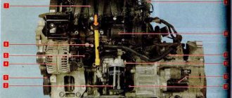
Diagnostics and repair of diesel engine turbine
Turbine diagnostics are carried out on a special computer stand, as well as by visual inspection during dismantling. Our car service has in its arsenal everything necessary to carry out high-quality and professional diagnostics of the engine and turbine of diesel and gasoline cars of any model.
Diagnostics of a diesel engine turbine includes:
- Visual inspection for play and external damage;
- Impeller performance assessment;
- Check for oil leaks through the O-rings.
After performing a thorough diagnosis and identifying problem areas, repairs are made. How to repair diesel engine turbines:
- Diagnostics are carried out;
- Disassembled for troubleshooting;
- All parts and components are cleaned;
- Worn seals, bearings and parts are replaced with new ones;
- The rotor is balanced using special equipment;
- The cartridge is checked for leaks and balanced.
At special stands, the operation of the turbine of your diesel engine is simulated. The check is carried out in all modes: at idle, under normal load, at high speeds.
Basic designs of steam turbines
Model of a single stage steam turbine
A steam turbine consists of two main parts. The rotor with blades is the moving part of the turbine. The stator with nozzles is the stationary part.
Based on the direction of steam flow, a distinction is made between axial steam turbines, in which the steam flow moves along the turbine axis, and radial steam turbines, in which the direction of steam flow is perpendicular, and the working blades are located parallel to the axis of rotation.
Based on the number of cylinders, turbines are divided into single-cylinder and two-three-, four-five-cylinder. The multi-cylinder turbine allows the use of larger available thermal enthalpy differences by placing a large number of pressure stages, the use of high-quality materials in the high pressure parts and bifurcation of the steam flow in the medium and low pressure parts. Such a turbine turns out to be more expensive, heavier and more complex. Therefore, multi-casing turbines are used in powerful steam turbine plants.
Based on the number of shafts, they are distinguished between single-shaft, double-shaft, and less often three-shaft, connected by a common thermal process or a common gear transmission (gearbox). The arrangement of the shafts can be either coaxial or parallel - with an independent arrangement of the shaft axes.
- The fixed part - the housing (stator) - is detachable in a horizontal plane to allow removal or installation of the rotor. The housing has recesses for installing diaphragms, the connector of which coincides with the plane of the turbine housing connector. Along the periphery of the diaphragms there are nozzle channels (grids) formed by curved blades cast into the body of the diaphragms or welded to it.
- At the points where the shaft passes through the housing walls, end seals are installed to prevent steam leakage to the outside (from the high pressure side) and air suction into the housing (from the low pressure side). Seals are installed where the rotor passes through the diaphragms to prevent steam from flowing from stage to stage, bypassing the nozzles.
A limit regulator (safety regulator) is installed at the front end of the shaft, which automatically stops the turbine when the rotation speed increases by 10-12% above the nominal one.