Introduction
It's no secret that many problems that sometimes arise with a car can be corrected even by a novice car owner.
Despite the apparent complexity of the mechanism, sometimes you can avoid another visit to the service center or the purchase of another unit for replacement. Anyone who wants to save money on purchasing a low-quality device can independently make, for example, a strobe light, which is designed for installing an ignition. Many beginners may be put off by the name, which seems too complicated and pretentious, but don’t rush to conclusions. To know how to make a strobe light for installing the ignition without purchasing an identical factory device, you should familiarize yourself with several proposed methods and stock up on all the necessary materials and tools. For those who are not confident in their abilities, it will be enough to go to a car store at least once and find out about the cost and quality of a production strobe light. In fact, almost the majority of car owners resort to using conventional gas-discharge lamps to create this cunning device. True, such devices cannot be distinguished by long-term operation, especially since the cost of a lamp that once fails is not very different from the amount for which you can purchase a new strobe light. All this together can prompt a car enthusiast to create his own device. Let's look at the simplest and most accessible methods of creating a strobe.
LED car strobe light
Most often, LEDs are used for indication. This is due to the extremely low service life of flash lamps. Of course, the LED is brighter, and its glow is clearly visible even in the sun. As a rule, the housing is made of plastic and consists of two halves. On one side there is a hole for an LED. It is worth noting that all elements are assembled on a printed circuit board.
The transformer has 2 windings. A wire diameter of 0.3 mm is used as the primary winding. The secondary one is made of wire with a diameter of 0.2 mm with a number of turns of 638. It is quite difficult to find a ferrite core with a coil. It can be removed from a failed PC power supply.
The inductive ring of the sensor is manufactured as follows. We take ferrite rings with a diameter of up to 4 cm and a total permeability of no more than 3,000 N m. About 36 turns of wire with a diameter of 0.8 mm must be wound directly onto the ring. All this can be covered with a layer of insulation. Thus, we have a ready-to-use automotive strobe light.
"Advantages" of factory devices
Before you decide to purchase a standard factory strobe, you need to study in detail all its features and learn about the principle of operation. So, let’s first understand the scope of application of this device. A device called a strobe light allows the car owner to easily adjust the ignition. Having this device at hand can significantly speed up the entire setup process. Equipped with a lamp, the unit gives signals about the presence of a spark, so you can quickly and correctly set the required ignition timing.
It is impossible not to note the efficiency and accuracy of efficient factory instruments that can cope with this task in just a few minutes. However, despite such advantages, for some reason the vast majority of car enthusiasts try to create such a unit with their own hands, without rushing to buy a production version. Most likely, this aspect is due to the rather high cost of stroboscopes. The overwhelming majority of factory models are equipped with expensive gas-discharge lamps, the subsequent replacement of which becomes equal in price to purchasing a new device. Commercially available factory analogues are sold in the price range from 1000 to 6000 rubles (a simple Multitronics will cost the buyer 1000 rubles, Astro L5 at 1300, Focus F1 at 1700, and Focus F10 at 5600 rubles).
If desired and the need arises, you can create such a device yourself, you just need to find all the materials that include the simplest and most ordinary things that are in everyone’s garage. A simple car strobe light can be made from a flashlight, LEDs, and even a simple laser pointer. Despite its almost complete pricelessness, a hand-made device will be able to serve no less durable and reliable, proving the effectiveness of the service in practice.
flash strobe for controlling the brake light on a car (motorcycle, bicycle...)
An acquaintance found such a “thing” on Ali, asked to buy it... we tested it, I decided to buy it for myself. Below is what it is designed for and is there a need for it. Arrived undamaged in a simple envelope.
The kit includes the device itself and a piece of double-sided tape for mounting.
In principle, I think it’s a pretty useful device, not so much for “beauty”, but for attracting ADDITIONAL attention when braking. Installed on additional feet. When you press the brake pedal, when the main “stops” simply light up, the additional stop first makes several flashes with different durations, then lights up... In reality, braking is more noticeable, especially in the initial phase. In some cars, the stop does not differ much in brightness from the dimensions, and you can simply not pay attention to the static “additional”... considering the price and ease of installation... DEFINITELY a useful device! Below is a short photo of the installation and a video of the work. Immediately checked the functionality
on an LED and later on 12V lamps, because there was a suspicion that on lamps the inertia of the filament could smooth out the blinking, and changing additional lamps would be a necessary item. stop signal
on lamps
Actually, the lamps actually blink a little more “smoothly”, although it still looks normal.
Next, for connoisseurs of dismemberment, I disassembled the object of study :)... there really wasn’t much to look at :) Although there is a plus in this - the circuit is protected from condensation at a minimum.
For installation, the car was chosen, on which I carry out most of the experiments with “modifications” and “collective farm tuning” () - probably this experience will not be the last. Any ideas :)))
The stop repeater housing was disassembled and a “black box” was installed there.
Well, or rather, it was my repeater that “it” didn’t fit into, I had to pull the board out of the case and insert it without it
Whether to replace the repeater lamp(s) with LEDs is certainly an interesting question. The power is stated at 1.2A (10-15W), the installed lamp (in my case) is 12V 5W. Those. theoretically it “works” - but how extreme the mode will be for it in the case of using a lamp with a higher power (there can be much more lamps installed there) ... and how the light bulbs will feel in the “flickering” mode (how often they will burn out) is of course a question "interesting". Since I was often too lazy to disassemble the stop repeater, I decided to immediately replace the lamp with an LED. Well, the actual result... How it works on the “experimental” car... and how it works on the neighbor’s car :))
In the process of replacing the lamp with an LED, I came across only a “spot” T10 format, which glows only upward, so in the video only the luminous POINT is visible, and the reflector does not work. If you change it to a luminous one “to the sides,” the luminous spot will increase (later I decided to replace it).
In principle, this strobe light can be used on motorcycles, bicycles, tractors and tanks.…
Pros: Inexpensive, easy to install, should significantly add “visibility” to your car when braking. Cons: To some extent, direct hands are needed, it is desirable to replace the lamps with LEDs, the box may not fit into the repeater, it will be necessary to either disassemble or install BEFORE the repeater.
UPD links to similar reviews mysku.ru/blog/aliexpress/32057.html mysku.ru/blog/aliexpress/26680.html
The principle of creating the device
A strobe light for ignition adjustment is especially necessary for those who have a car with a carburetor. This is due to the peculiarities of the settings, since it is difficult to imagine correctly even in the mind, not to mention in reality, the ignition timing, which is present on contact distributors and all contactless distributors. It is simply impossible to cope in such a situation without a strobe light. Moreover, by using the services of this most precise device, you can adjust the ignition with extreme precision in just 7–8 minutes. This indicator, like other important elements of the car, must be given due attention, since without it the normal functioning of any vehicle is impossible. The need for such a product, the high cost of the factory version in the store and the availability of the necessary parts simply push a person to create his own strobe light.
List of required parts
Before you go to the store to purchase all the parts described below, you should carefully study all the materials and parts present in the garage; it is quite likely that most of them have been collecting dust on the shelves for a long time without any particular need. If you find most of the elements stored among waste materials for the manufacture of the device, the final cost of a finished and perfectly functioning strobe light will not exceed 100 rubles, which will save money for other needs. The first thing you need is a simple, cheap Chinese-made flashlight. It will be better if it is LED. If the available model turns out to be a lamp model, you will need to additionally purchase or remove all the required LEDs from the old flashlight.
In addition to the body, you will need electronic filling, the creation of which requires the following elements:
- transistor type KT315, which is probably stored in a discarded Soviet-style radio;
- thyristor KU112A, it can be found in the power supply of an old TV;
- capacitor designed for voltage 16 V;
- diode with low frequencies;
- relay for 12 V voltage, but you should choose a small part that can fit in the flashlight body;
- several "crocodiles";
- a coil of wires, 0.5 meters of which must be shielded;
- a small piece of copper wire.
Despite the wide variety of circuits created for the correct sequential assembly of the device, the newly minted creator of the strobe will in any case need such a supply of spare parts. In addition to having all the described parts, you need to arm yourself with a soldering iron; it will be better if the car owner has at least minimal skills in using it.
To assemble this device, you need to connect all the parts in series with the existing wires and solder them securely. Through the rear hole in the flashlight, you will have to pass all the necessary wires that will ensure uninterrupted power supply to the strobe. If the selected flashlight model does not have a side hole, the car owner must make it himself. This is necessary in order to bring out a shielded wire, at the ends of which copper wire will be soldered to the central core. It is this element of the created device that will be a special signaling sensor.
Operating principle of the device
So, after creating such an important device as a homemade car strobe light, you should understand the principle of its operation in order to seamlessly adjust the ignition angle in the future. A capacitor to which an electric current is applied is charged by a resistor. When the charge reaches the required level, the current is supplied by a resistor to the opened transistor. It is at this time that the relay begins to work, which is designed to create a circuit including a thyristor, diodes and a capacitor. The entire unit is a specialized divider through which the charge passes to the main contact of the thyristor. The opened control element entails the discharge of the capacitor, which is expressed through the lighting of the diodes. The flash of light that appears in the flashlight goes out. The main output of the transistor is connected through a thyristor and resistor to the central wire, as a result of which the transistor closes and the relay turns off.
The strobe for setting the ignition is signaled by a long glow of the diodes; this occurs due to a broken contact with a delay. After some time, the contact is de-energized and interrupted. The homemade device again assumes a state of inactivity, flashing at the moment the next impulse occurs. To achieve a brighter glow of the LEDs in the flashlight, you can use a capacitor with a larger capacity.
Creating a strobe light on a chip
The simplest strobe for installing the ignition is to create a device that is based on the DD1 microcircuit, which is a single-vibrator. Several diodes are connected to this microcircuit, which help protect it from possible errors that occur during connection. Before the next pulse hits the microcircuit, it is in its usual quiet state. The system is equipped with two different pins, with the first having a low level, which is opposed by a high inverse pin. Accordingly, the connected capacitor is connected with a plus to the inverse terminal, due to which it is charged. A pulse passing through the entire microcircuit “hooks” a trigger, behind which a charged capacitor is connected to operation. The entire process takes place directly through the resistor. The soldered-in DD1 chip responds to the electric current supplied to it, displaying the energy through the glow of LEDs.
Instructions for the manufacture of a device for installing the ignition
The easiest way to get a strobe light and use it to properly adjust your car is to purchase such a device at a car dealership. The only “but” in this decision can only be the considerable price of the devices, which can significantly affect the driver’s home budget. Therefore, many prudent motorists choose the second, economical option - making a strobe light for installing the ignition with their own hands. As practice shows, such home-made devices, as a rule, are in no way inferior to industrial designs, regardless of what format they are made. Be it a device using a domestic or foreign timer, a homemade strobe light using reliable LEDs, or another option.
In any case, a homemade product made from simple and cheap materials will cost several times less than buying a device. Assembly diagrams for such devices can be easily found on the Internet or from those experienced drivers who have already made such a device in a housing from an old camera or radio on their own and successfully use it not only for installing the ignition, but also checking spark plugs and other control purposes. There are many such schemes, and from them you can always choose a few of the simplest ones that do not require a large amount of work.
What is a strobe
A stroboscope is a device for observing objects making rapid, periodically repeating movements. To do this, it illuminates a moving object with bright flashes of light, repeated with a frequency equal to the frequency of movement of this object. In this light, a moving object appears motionless. In a car engine, using a strobe light, you can determine the ignition timing angle. To do this, you need to synchronize the flashes with ignition pulses in the first cylinder, and direct the light to the TDC and ignition timing marks, illuminating the crankshaft pulley with a mark.
Factory-made stroboscopes usually have an inertia-free flash lamp as a light flash emitter, which allows you to adjust the ignition timing even in bright sunlight. However, it has a short service life and is not always on sale. Therefore, with the advent of LEDs with a luminous intensity of more than 2000 mcd, it became more convenient to use them when making a strobe light with your own hands. To convince us of the significant superiority of the luminous flux parameters of the new LEDs, let us recall that the AL307, with the same current consumption, has a luminous intensity of only 10–16 mcd. (diagram for video materials in the description under the video)
Materials
The strobe circuit proposed for making it yourself is simple and does not require complex settings. To make a simple strobe for adjusting the ignition timing with your own hands, you will need the following tools, parts and materials:
- Pocket flashlight with a large enough battery compartment.
- LEDs KIPD21P-K – 9 pcs.
- Chip K561TM2 (two two-stage D-triggers). Russian analogues: K176TM2, 564TM2; imported analogue – CD4013/HEF4013.
- Transistor KT315B – 2 pcs. (VT1, VT2); KT815A – 1 pc. (VT3).
- Trimmer resistor SPZ-196 or SP5-1 with a resistance of 33 kOhm.
- Fixed resistors 5.1 Ohm - 3 pcs., 3 kOhm - 1 pc., 15 kOhm - 1 pc., 20 kOhm - 2 pcs., 330 kOhm - 1 pc., with a power of at least 0.125 W.
- Diode KD213 or any other medium power with Urev. max not less than 16 V.
- Non-polar capacitors KM-5, K73-9 or others. C1 must have an operating voltage of at least 200 V, the rest not less than 16 V. 0.068 µF - 3 pcs., 47 pF - 1 pc.
- Any toggle switch to turn on the power of the device.
- 1 m of shielded wire (for example, antenna).
- 3 alligator clips.
- A small piece of foil PCB 1 mm thick.
- Stranded double insulated copper wire – 1.5 m.
- Glue gun.
- Soldering iron, solder, flux.
Device design
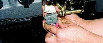
The body of the strobe light will be a flashlight. The circuit is assembled by hanging installation. The finished circuit is filled with hot plastic from a glue gun, and after the filling has hardened, it is placed in the battery compartment of the flashlight. The power and signal cables are routed out through holes drilled in the housing. You need to solder clips to the ends of the power wires, indicating the polarity. Connect the antenna cable to the strobe input. Solder an alligator clip to the central core of the input cable. After connecting the strobe to the car engine, it will use it to send synchronization pulses from the high-voltage ignition wire to the input. To make this possible, it is enough to put it on the insulation of the high-voltage ignition wire of the first cylinder of the car engine. The synchronization pulse will go through the capacitance formed by the central core of the ignition wire and the clamp. That is, a simple homemade capacitive sensor will consist of an alligator clip placed on a high-voltage wire.
Car strobe light
For a car enthusiast
Home For radio enthusiasts For car enthusiasts
Material provided by Radio Amateur magazine
Motorists are well aware of how important it is to correctly set the initial ignition timing, as well as the proper operation of the centrifugal and vacuum ignition timing regulators. Incorrect setting of the ignition timing by just 2-3° and malfunctions of the regulators can cause increased fuel consumption, engine overheating, loss of power and can even shorten the service life of the engine.
However, checking and adjusting the ignition system are quite complex operations that are not always accessible even to an experienced car enthusiast.
A car strobe light allows you to simplify the maintenance of the ignition system. With its help, even an inexperienced car enthusiast can check and adjust the initial setting of the ignition timing within 5-10 minutes, as well as check the serviceability of the centrifugal and vacuum timing regulators.
The operation of a strobe is based on the so-called stroboscopic effect. Its essence is as follows: if you illuminate an object moving in the dark with a very short bright flash, it will visually appear as if motionless “frozen” in the position in which the flash caught it. By illuminating, for example, a rotating wheel with flashes that follow at a frequency equal to the frequency of its rotation, you can visually stop the wheel, which is easy to notice by the position of any mark on it.
To set the ignition timing, start the engine at idle speed and illuminate the special setting marks with a strobe light. One of them, movable, is located on the crankshaft (either on the flywheel or on the generator drive pulley), and the other is on the engine housing. The flashes are synchronized with the moments of spark formation in the spark plug of the first cylinder, for which a capacitive strobe sensor is mounted on its high-voltage wire.
In the light of the flashes, both marks will be visible, and if they are exactly opposite one another, the ignition timing is optimal, but if the movable mark is displaced, the position of the distributor-distributor is adjusted until the marks coincide.
The main element of the device is a pulsed inertia-free stroboscopic lamp N1 type SSh-5, the flashes of which occur when a spark appears in the spark plug of the first cylinder of the engine. As a result, the timing marks on the flywheel or crankshaft pulley, as well as other engine parts that rotate or move synchronously with the crankshaft, appear motionless when illuminated with a strobe lamp. This makes it possible to observe the shift between the ignition timing and the moment the piston passes the top dead center in all engine operating modes, i.e., to monitor the correct setting of the initial ignition timing and check the functionality of the centrifugal and vacuum ignition timing regulators.
The electrical circuit diagram of a car strobe light is shown in Fig. 1. The device consists of a push-pull voltage converter on transistors VI, V2, a rectifier consisting of a rectifying unit VЗ and a capacitor C1, limiting resistors R5, R6, storage capacitors C2, C3, a strobe lamp H1, a lamp ignition circuit consisting of capacitors C4, C5 and arrester F1 and protective diode V4.
Fig.1. Electrical circuit diagram of a car strobe light using germanium transistors.
The device works as follows. After connecting terminals X5, X6 to the battery, the voltage converter, which is a symmetrical multivibrator, starts working. The initial opening voltage to the bases of transistors V1, V2 of the converter is supplied from dividers R2-R1, R4-R3. Transistors V1, V2 begin to open, and one of them is necessarily faster. This closes the other transistor, since a blocking (positive) voltage will be applied to its base from winding w2 or w3. Then transistors V1, V2 open alternately, connecting first one or the other half of the winding w1 of transformer T1 to the battery. In the secondary windings w4, w5, an alternating rectangular voltage with a frequency of about 800 Hz is induced, the value of which is proportional to the number of turns of the windings.
At the moment of spark formation in the first cylinder of the engine, a high-voltage pulse from the distributor socket through a special plug X2 of the spark gap and capacitors C4, C5 is supplied to the igniting electrodes of the stroboscopic lamp H1. The lamp lights up and storage capacitors C2, C3 are discharged through it. In this case, the energy accumulated in capacitors C2, C3 is converted into light energy from the lamp flash. After the discharge of capacitors C2, C3, lamp H1 goes out, and the capacitors are again charged through resistors R5, R6 to a voltage of 420-450 V. This completes the preparation of the circuit for the next flash. Resistors R5, R6 prevent short-circuiting of the windings w4, w5 of the transformer at the moment the lamp flashes; diode V4 protects the transistors of the converter if the strobe is accidentally connected in the wrong polarity.
The F1 spark gap, connected between the distributor and the spark plugs, provides the necessary high-voltage pulse voltage to ignite the lamp, regardless of the distance between the electrodes of the spark plug, the pressure in the combustion chamber and other factors. Thanks to the spark gap, uninterrupted operation of the strobe is ensured even with short-circuited spark plug electrodes.
In the case of replacing germanium transistors P214A with silicon ones of the KT837D(E) type, the converter circuit, and indeed the entire strobe, must be significantly changed. The transformer data changes and additional requirements for its design are put forward. This is due to the fact that silicon transistors of the KT837 series are higher frequency and the circuit made on them is prone to excitation. In addition, to open these transistors, a higher voltage is needed than for germanium transistors. So, for example, if in a strobe, assembled according to the diagram in Fig. 1, solder instead of P214A transistors, for example, KT837D transistors, without changing anything, the converter will not work, both transistors will be closed, in order for the converter to start working, the resistance of resistors R2, R4 must be reduced to 200-300 Ohms. At the same time, the efficiency of the converter decreases, and most importantly, without any apparent reason it can begin to generate high-frequency sinusoidal oscillations with a frequency of 50-100 kHz. power supply, prevent the occurrence of high-frequency generation.
The power dissipated in the transistors increases sharply, and the transistor fails within a few minutes. In Fig. Figure 2 shows an electrical circuit diagram of a car strobe light using KT837d silicon transistors. The power dissipated in the transistors of the converter is significantly less in this case due to the higher speed of the KT837D transistors, and consequently, the greater steepness of the converter pulse fronts; The reliability of the converter is also higher. Let's consider the features of this scheme. Capacitors C1, C7, converters connected between the bases of the transistors and the minus of the power supply, prevent the occurrence of high-frequency generation.
Fig.2. Electrical circuit diagram of a car strobe light using silicon transistors
The initial unlocking bias to the bases of transistors V6, V7 is supplied from fairly high-resistance voltage dividers R3, R2, R1, R9, R1О, R11 with a total resistance of about 1000 Ohms, the lower shoulders of which have a resistance of 100 Ohms (division coefficient 1/10). However, thanks to diodes V5, V10, the base current of the transistors from the windings w1, w3 flows through low-resistance resistors R1, R11 (10 Ohms). Thus, it is possible to fulfill two contradictory requirements: to obtain a high-resistance divider for the initial bias with a low-resistance resistor in the base current circuit.
Circuits C2, R5 and C3, R4 reduce to an acceptable level the voltage surges that occur when transistors V6, V8 are closed, which are a consequence of their excessive speed. The values of C2, C3, R4, R5 are selected experimentally for each specific design of transformer T1. Resistor R8 ensures the discharge of capacitors C4, C5, C6 in the intervals between these emissions, so that the voltage on the capacitors when the engine is stopped does not exceed the norm. Diodes V7, V9 eliminate reverse surges of the collector current of transistors V6, V8 at the moments of their closing. Without these diodes, the amplitude of the reverse current surge reaches 2 A. In addition, these diodes protect transistors V6, V8 in case of incorrect polarity of the strobe connection.
Unfortunately, the service life of flash lamps is short, and purchasing a new one of the right type is not easy. With the appearance on the market of domestic LEDs with a luminous intensity of more than 2000 mcd (for comparison, the LEDs of the ALZO7-M series with the same current have a value of 10...16 mcd), it is possible to use them in amateur stroboscopic devices. The design described below uses a group of nine red KIPD21P-K LEDs. The device is powered from the vehicle's on-board network. Diode V1 (see diagram in Fig. 3) protects the strobe from erroneously changing the polarity of the supply voltage.
Fig.3. Electrical circuit diagram of a car strobe light using LEDs.
The capacitive sensor of the device is a conventional alligator clip, which is attached to the high-voltage wire of the first spark plug of the engine. The voltage pulse from the sensor, passing through the circuit C1 R1 R2, is supplied to the clock input of the trigger DD1.1, turned on by a one-shot device.
Before the pulse arrives, the one-shot device is in its initial state, the direct output of the trigger is low, and the inverse output is high. Capacitor C3 is charged (plus on the inverse output side), it is charged through resistor R3. A high-level pulse triggers the one-shot device, while the trigger switches and the capacitor begins to recharge through the same resistor R3 from the direct output of the trigger. After about 15 ms, the capacitor will charge enough that the flip-flop will again be switched to the zero state at the R input.
Thus, the one-shot device reacts to a sequence of pulses from a capacitive sensor by generating a synchronous sequence of high-level rectangular pulses with a constant duration of about 15 ms. The duration of the pulses is determined by the ratings of the RЗСЗ circuit. The positive swings of this sequence trigger the second one-shot, assembled according to the same circuit on the DD1.2 trigger.
The pulse duration of the second monovibrator is up to 1.5 ms. At this time, transistors VT1 - VT3, which make up the electronic switch, open, and powerful current pulses - 0.7...0.8A - flow through the group of LEDs HL1-HL9.
This current significantly exceeds the rated value of the maximum permissible pulsed forward current (100 mA) established for LEDs. However, since the duration of the pulses is short, and their duty cycle in normal mode is at least 15, overheating and failure of the LEDs were not observed. The brightness of the flashes, which is provided by a group of nine LEDs, is quite sufficient for working with a strobe even during the day.
In order to verify the reliability of the device, a control electrical run of the light emitter was carried out at a pulse current of 1 A for an hour. All LEDs passed the tests, and no overheating was detected. Note that usually the time of using the device does not exceed five minutes.
It has been experimentally established that the duration of flashes should be within 0.5...0.8 ms. With a shorter duration, the feeling of a lack of brightness of the illumination of the marks increases, and with a longer duration, their “blurriness” increases. The required duration can be easily selected visually while working with a strobe using trimming resistor R4, which is included in the timing circuit R4C4 of the second monostable.
The purpose of the first one-vibrator is to protect the LEDs from failure when the engine speed of the crankshaft is accidentally increased while using a strobe.
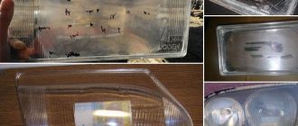
We created a model of a car strobe light based on the LED principle (see Fig. 4 (a, b)). The body is the body of the flashlight.
Fig.4(a). Electric strobe light assembly.
Fig.4(b). Electric strobe light assembly.
Tests of the assembled device were carried out successfully; it is used in the garage of the Stavropol State Agrarian University.
The functions of the strobe can be expanded to turn it into a tachometer. Because Many old-style cars that are still in use do not have this device on the driver's dashboard.
For this purpose, an adjustable frequency generator (AGF) has been assembled for a pulse repetition rate of 10 - 15 Hz, which corresponds to a crankshaft rotation speed in the range of 600-900 rpm. This range usually contains the minimum engine speed at idle, at which the initial ignition timing is adjusted.
The handle of the variable resistor included in the frequency-setting circuit of the RC generator was equipped with a scale calibrated using a laboratory digital frequency meter. The output signal of the GRCH is supplied to the input instead of the sensor to the input of the strobe.
The auto mechanic, having connected the device, directs an intermittent light stream, as in the previous case of setting the ignition, to the crankshaft pulley and, if necessary, adjusts it to the value specified by the manufacturer for this vehicle.
After adjusting the crankshaft speed, he proceeds to adjusting the ignition timing according to the method described above, see 1-2.
Because Since the accuracy of determining the crankshaft rotation speed is low, this allowed us to take such a simple solution without resorting to developing a digital version of the tachometer.
Bibliography:
- Belyatsky P. LED car strobe / P. Belyatsky - “Radio” - 2000 - No. 9, p. 43
- Sinelnikov A.Kh. Electronics in the car / A.Kh. Sinelnikov - Moscow: Radio and Communications, 1985, p.82
- Yutt V.E. “Electrical equipment of a car” - Moscow: Transport, 1995
- Chizhkov Yu.P. Anisimov A.V. “Electrical equipment of a car” - Moscow: “Behind the wheel”, 1999
- Bannikov S.P. “Electrical equipment of a car” - Moscow: Transport, 1993
- Shiga H. Mizutani S. “Introduction to Automotive Electronics” - Moscow: MIR, 1989
Date of publication: 03/21/2007
Readers' opinions
- Max. / 03/20/2011 — 03:46 I assembled a circuit using LEDs. It worked right away.
You can leave your comment, opinion or question on the above material:
Using the device
To set the advance angle (moment) with your own hands, use a device to illuminate the setting marks while the car engine is idling. One of them is located on the rotating parts of the car engine (on the crankshaft pulley or on the flywheel). The second mark is stationary, it is located either on the cover of the front part of the car’s cylinder block, or on the gearbox housing. If in the light of the device the movable mark appears to be opposite the stationary mark, the car’s ignition is normal and does not require adjustment of the timing (angle) of advance.
If the marks do not match, to adjust the timing, you need to change the position of the distributor accordingly. To delay the ignition timing, you need to turn the distributor in the direction of rotation of the slider, and to do it earlier, in the opposite direction. If sparking in your car is controlled by a microprocessor, look for a faulty sensor or entrust the solution to this problem to professionals.
With a strobe light, setting the ignition on a carburetor engine is always much more convenient than “by ear”. But the price tags for such equipment sometimes “bite,” which pushes many motorists to alternative solutions to this issue, for example, by making a strobe light with their own hands.
A little about setting up a strobe
If a high-quality board was used and everything works fine, then no configuration is required. But often this is not the case. Therefore, the circuit should be assembled sequentially, one by one. You need to understand that first one microcircuit is soldered, then the second, third, etc.
In conclusion, I would like to note that a car strobe light may not have a board at all. You just need to take a flashlight and correctly connect the indicator to the high-voltage wire of the spark plug of the 1st cylinder. Such a device will also work. If you press the gas pedal while the engine is running and hear a click after 3-5 seconds of operation, then the ignition is early. If there is no knocking or clicking at all, then it is later. The distributor is adjustable left and right.
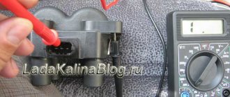
To check if the device works, you just need to take a piezo element from a lighter or something like that. If the lamp lights up with each spark, then the car strobe light was made correctly with your own hands, but if not, then you need to check the circuit again. Perhaps a contact has come loose somewhere.
Average price of a factory product and its disadvantages
The factory version of the device has some disadvantages that significantly reduce the usefulness of such an acquisition.
It is always more convenient to set the ignition on carburetors with a strobe light
Firstly, the cost of factory stroboscopes is quite considerable. So the digital model Multitronics C2 will cost the buyer about 900-1000 rubles. The more functional AstroL5 strobe will cost 1,300 rubles. Focus F1 - a model suitable for servicing both gasoline and diesel engines - will require 1,700 rubles, its more “advanced” brother Focus F10 - 5,600 rubles.
Secondly, manufacturers often use an expensive gas-discharge lamp in the design of their products. It has a limited resource and may require replacement after a short time, which will not only hurt your pocket, but will be tantamount to buying a new strobe light.
Strobe light
Another interesting model is strobe lights. Such lighting systems have two operating modes: normal and, in fact, stroboscopic.
Please note that when the flashlight is operating in stroboscopic mode, the following consequences are possible:
- disorientation;
- impairment of peripheral and direct vision;
- the appearance of short-term confusion and fear.
In this regard, such devices can be used as an element of self-defense when attacked by aggressive persons in the dark. Very often police officers use such devices in their work.
How to make a strobe light with your own hands
There can be many options for designing a “home” strobe. However, in general, all such projects are structurally similar. Let's look at the principle of assembling this gadget using the following example.
Required parts:
- transistor KT315 (you can find it in any radio equipment of a bygone era, it can have different letter indices);
- thyristor KU112A (easy to find in the switching power supply of ancient TVs);
- small-sized resistors with a power of 0.125 W;
- a cheap (Chinese) flashlight with diodes (the number of diodes may vary, but better - from 6 to 10 pieces);
- capacitor C1 for voltage from 16 Volts;
- diode V2 - any low-frequency, for example KD105 or D9;
- small-sized relay (index BS-115-12A-DC12V or RWH-SH-112D, 12 Ampere, coil - 12 Volt); however, you can also use domestic relays, for example, type RES-10, with a coil voltage of 12 Volts;
- power wires of the required length (about 0.5-0.6 m) and alligator clips for connecting the strobe to the battery;
- shielded wire up to 0.5 m, a piece of copper wire about 10 cm.
How to connect everything, strobe diagram
Strobe connection diagram
All the main parts of the device can be conveniently placed directly in the body of a pocket flashlight or a regular camera flash. At the same time, power wires pass through the rear hole of the flashlight (photoflash); at the ends they have soldered crocodile terminals of different colors or with markings (so as not to confuse “plus” and “minus”). A hole is drilled in the side wall of the housing (if it is missing) to route a shielded wire through it to pin X1. The braiding of this cable at the end must be insulated; a piece of copper wire about 0.1 m long must be soldered to the main core - this is a strobe sensor.
Characteristics of a strobe light for ignition installation
Like any important automotive device, a strobe light has a system of certain characteristics that allow it to clearly fulfill its mission. Some of them are unique to him. Let's say, it can be powered in two equivalent ways: from its own batteries or from the on-board power system of the machine. Moreover, the first method, according to many experts, is more practical, since it does not require connecting wires to the device.
A distinctive property of a strobe is considered to be the minimum frequency of its flashes; it should be equal to the speed of the crankshaft at maximum speed. The most common is a device with a frequency of 50 Hertz. It is also worth noting that such a device can operate effectively only for a short time - about 10 minutes, which is due to the specific design of the lamps, which is emphasized by the instructions supplied with it.
The operation of a strobe to set the ignition from a flashlight or flashlight
According to the diagram, after connecting the power wires to the battery, capacitor C1 begins to quickly charge through resistor R3. Upon reaching a certain degree of charge, the voltage through resistor R4 and the LEDs begins to flow to the base of the opening transistor. At this moment, relay P1 should operate. By closing, the relay contact prepares a circuit that consists of a thyristor, relay contact P1, LEDs and capacitor C1. Through dividers R1 and R2, the control electrode of the thyristor receives a pulse from contact X1.
The thyristor opens, resulting in a rapid discharge of the capacitor through the LEDs. A bright flash of a flashlight is observed.
By means of resistor R4 and a thyristor, the base of the transistor is connected to the common wire, which causes the transistor to close and the relay to turn off. At the same time, the glow period of the LEDs increases by several milliseconds due to the fact that the contact does not open immediately - due to the slight inertia and residual magnetization of the relay armature. After the contact opens, the thyristor is de-energized. The electrical circuit returns to its original state until a new impulse passes. By changing the capacitance of the capacitor used, you can change the glow time of the LEDs: more capacitance means they glow longer and brighter, but the trail from the mark on the flywheel is more noticeable.
How to use this strobe light
Using a garage-made strobe, you can easily and with great accuracy:
- set the ignition on a carburetor engine;
- check the spark plug or ignition coil;
- check the operation of the centrifugal and vacuum ignition timing regulator.
Homemade strobe is cheaper and more reliable
In order for the ignition timing to be set correctly, it is necessary to assume that the mixture is usually ignited a couple of degrees before the piston reaches the top stroke point. This angle is called the “ignition timing angle”. As the crankshaft speed increases, the SOP should also increase along a given curve. As a result, the advance angle is set at idle and then controlled in all engine operating ranges up to 5000 rpm.
When connecting a strobe, you need to wind its sensor (copper wire) directly onto the sheath of the high-voltage wire of the first cylinder of the internal combustion engine. Three or four turns will be enough. In this case, it is necessary to fix the wire in this way as close to the spark plug as possible - in order to minimize the influence of neighboring wires on the operation of the strobe. To power the device, its wires with “crocodiles” cling to the terminals of the battery. For better visibility, you will also have to additionally mark the flywheel mark with a white dot - paint or, for example, a clerical touch.
Installation of UOZ:
- Start the engine and warm it up to operating temperature, leaving it idling within 600-800 rpm.
- Connect the strobe power wires.
- Wind the copper sensor wire onto the armor wire of the first cylinder.
- Point a flashlight, flash, laser, etc. to a fixed mark (located on the timing case).
- Then find the same moving point on the flywheel pulley.
- If the moment is violated, the moving and static marks will be relatively far from each other.
- By rotating the ignition distributor housing, ensure that the marks match and fix the distributor in this position.
- Next, you need to briefly raise the speed, as a result of which the marks will diverge again. But it normal. In this mode, the ignition is set earlier. To check this indicator, a pair of fixed marks are provided - after 5 degrees of ignition timing.
- For 3 thousand rpm, the SOP in the case of VAZ engines is 15-17 degrees.
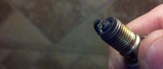
- To check the serviceability of the spark plug, alternately wind the copper wire onto the high-voltage wires and see if there are any missing pulses. A lower frequency of LED flashes will indicate a misfire, “punching” the spark plug into the housing.
How does a strobe light work for ignition?
Every self-respecting driver should have basic skills in handling a strobe light, since this device acts as his reliable assistant and ally in the economical use of the car. Moreover, there is nothing too complicated about it: anyone can learn how to work with a strobe, since it is a simple device that can be purchased in almost every specialized car store.
It works on the basis of the stroboscopic effect, known from school physics lessons. The essence of this effect is simple. So, when illuminating an object moving in the dark with a short bright flash, this object will seem motionless, frozen in exactly the same angle in which it was at the moment of the flash. Next, two special marks should come into play, which will have to work synchronously with the strobe light. The location of the first, so-called “moving” one is the crankshaft, in other versions – the generator drive pulley, as well as the flywheel, and the second is the engine housing.
LED strobe for adjusting ignition timing
The engine is turned on at idle and, using a strobe, these marks are illuminated during a flash that occurs simultaneously with the appearance of a spark in a spark plug of a cylinder. In this case, you should record how the marks are located relative to each other. If they are placed exactly opposite one another, this means that the ignition timing is optimal, i.e. the engine will start perfectly. When the “movable” mark is displaced, the distributor-breaker requires adjustment so that the marks exactly oppose each other.