Design of the GAZ-53 ignition system
In order to repair and configure the SZ on the GAZ-53, you need to know how it works.
These trucks are equipped with a contactless protection system, which consists of the following components:
- power source – battery;
- switch;
- wires;
- additional relay;
- coil;
- breaker-distributor;
- current indicator;
- resistor element;
- ignition switch (switch).
Knowing the structure of the protection system, the connection diagram of the protection device and its other components, as well as the functions that each element performs, you can identify problems based on their symptoms and eliminate their cause. All components of the system can be divided into groups according to the tasks performed.
For normal operation of the internal combustion engine, the following conditions must be met:
- powerful spark;
- correspondence between the formation of a spark and the operation of the power unit;
- no missed spark formation.
The entire electronic ignition system consists of two circuits: primary and secondary.
The primary includes the following elements:
- Battery with multi-core cables of large cross-section;
- a switch that supplies power to the circuit;
- primary winding;
- breaker distributor located in the distributor;
- switching device that ensures stable operation;
- the resistance necessary for successful starting of the engine and unloading the short circuit, preventing its overheating.
The secondary circuit includes:
- distributor;
- wires for supplying high voltage current;
- candles.
When the primary circuit receives power, a magnetic field is generated in the breaker. The rotation of the distributor interrupts the current in this place, which leads to the disappearance of the magnetic field. At this moment, a signal appears on the secondary winding, which goes to the cylinders.
Photo gallery
It is necessary to set the ignition timing of the GAZ-53 accurately, since with deviations the engine power decreases and fuel consumption increases. In addition, burnout of valves, pistons, breakdowns in the cylinder head gasket and other problems associated with detonation are possible.
Therefore, the final adjustment is performed with the engine running, which warms up to a coolant temperature in the range of 80 - 90 degrees. With the engine running at idle speed, you need to loosen the fasteners of the distributor with a 10mm wrench so that it can be turned. After slightly turning the distributor counterclockwise, tighten the fastening bolt.
Pressing on the gas is how the power unit works. If you hear a “ringing of fingers,” that is, detonation occurs, turn the distributor clockwise in the opposite direction. Through trial and error we set the desired advance angle.
The test is done on a moving vehicle. With stable operation of the power unit, tuning is no longer needed.
Sometimes the distributor is pushed to the extreme position, but the adjustment is not enough. In this case, you need to check the position of the distributor drive relative to the engine.
A check is performed with the engine not running:
- First, marks are placed on the front crankshaft pulley. They must match on the 1st and 6th cylinders. To avoid making a mistake, it is better to remove the valve covers from the first 4 cylinders and check the valves. If the valve marks are in the correct position, the valves in the 1st cylinder will be free.
- Having removed the distributor, we inspect how the drive is installed. If it is located parallel to the motor, then it needs to be replaced or repaired; adjustment, in this case, will not help.
- If the position of the drive is incorrect, you need to unscrew the fastening nut and remove the part.
- After the drive is completely installed in its place, you need to check that the groove for the distributor runs parallel to the internal combustion engine (in the direction of travel of the car), and a small section of the bushing on the distributor faces the 4th and 8th cylinders (towards the driver) . By experience, you need to achieve the correct position of the distributor drive.
Detailed guide to setting up the ignition
Motorists have long been convinced of the advantages of electronic (non-contact) ignition, which does not have the disadvantages of contact ignition, for example, there is no need to adjust the gap in the contact group. In this article we will look at how to adjust for the 1st cylinder.
There are marks and castings on the cylinder head cover and crankshaft pulley.
Using the marks you can adjust the ignition timing:
- the first mark, located clockwise, means that the ignition timing is 10°;
- the middle mark is designed to set the lead angle to 5°;
- the shortest, last mark sets the advance angle to 0°: in this case, the mixture will ignite when the piston reaches top dead center.
The marks are aligned by rotating the crankshaft, either by a ratchet, or by using a special wrench on the nut.
Tools and materials
In order to complete 2106, you need to prepare the following tools:
- key for unscrewing spark plugs;
- special key for rotating the crankshaft;
- key to "13";
- control device: 12 V indicator light or voltmeter.
Stages
The ignition is set step by step:
We have set the ignition, now we need to check whether the setting is correct by following these steps:
- The check can be performed while the machine is moving. First you should warm up the engine and then accelerate it to a speed of 40-50 km/h. Upon reaching this speed, switch to fourth speed and drive for some distance without accelerating.
- Then you need to sharply press the gas pedal. 2-3 seconds after this, detonation and sounds resembling finger snapping should appear. The sounds should stop as the vehicle accelerates after approximately 5 km.
- If detonation does not occur, it is necessary to adjust the position of the distributor. The reason may be “early” ignition. If detonation does not occur, then the reason may be “late” ignition. If “early”, you need to turn the distributor to the right one degree. When “late” - one degree to the left. The procedure should be performed until detonation lasts 1-1.5 seconds.
- Having completed the adjustment, you need to put a dash on the distributor with paint showing the position of the mark with an average length in relation to the cylinder block.
- Next, you need to install the distributor correctly. First, you should again use the unscrewed spark plug and close the hole with your finger to set the first cylinder to TDC.
- Next, you need to align the mark on the crankshaft with the mark on the timing cover. To do this, turn the crankshaft clockwise.
- After removing the cover from the distributor, you need to install the slider. Its position should coincide with the imaginary straight line from the contact on the cover of the first cylinder.
- After all the steps, we put the distributor housing in place. This completes the ignition setup on the VAZ 2106.
Device
The ignition system of the GAZ 53 car is currently contactless. Having studied the device and principle of operation, you can simultaneously master troubleshooting skills. This is especially necessary for those who operate GAZ 53. After all, it often happens that there are no good specialists nearby who would help in solving problems that arise. In addition, you will have to pay for their services. The quality of the work done can sometimes be determined after some time. A malfunction that occurs unexpectedly and at the wrong time will create trouble.
System elements
The ignition system of the GAZ 53 car consists of several elements, each of which performs its own function. Knowing them, you can find and fix the problem much faster. The system consists of the following elements:
- Rechargeable battery;
- Switch;
- Spark plug;
- Sensor distributor;
- High-voltage and low-voltage wires;
- Ignition coil;
- Additional starter relay;
- Additional and noise suppression resistor;
- Current indicator;
- Egnition lock.
All constituent elements can be grouped depending on the tasks performed. In this case, they will be included in the appropriate groups. The ignition system of the GAZ 53 car will work correctly when the basic conditions are met:
- Comparison of the moment of spark occurrence and engine operation;
- Sufficient spark power;
- No gaps in sparking.
To supply a spark in a timely manner, you need to carefully correlate the engine operating cycles and the appearance of voltage on the spark plug electrodes. The required spark power, in turn, depends on the voltage, the gaps between the electrodes of the spark plug and the serviceability of the circuit. The lack of a spark leads to a decrease in power and an increase in fuel consumption, so misfires are unacceptable.
A Timely Spark
Comparison of a certain stroke and voltage supply to the spark plugs is the task of the distribution sensor. The contactless ignition system of the GAZ 53 car can be equipped with a magnetoelectric or semiconductor sensor-distributor, which is located inside the distributor. The list of distributor elements includes:
- Sensor-distributor;
- Current carrying plate (runner);
- Centrifugal and vacuum regulator.
The GAZ 53 magnetoelectric sensor is a generator of alternating current pulses, the frequency of which depends on engine speed. This device has eight poles (according to the number of cylinders). During the rotation of the camshaft, and with it the sensor rotor, the poles of the permanent magnet sequentially pass through the poles of the stator winding. As a result of the changing magnetic flux, an induced emf is induced in the winding, which creates a control pulse for the commutator.
The centrifugal regulator rotates the sensor rotor relative to the stator, which, in turn, changes the ignition timing of the GAZ 53. This occurs when the engine crankshaft speed increases. The regulator weights, overcoming the force of the springs, turn the rotor. Thus, the effort must be certain, otherwise it will affect the operation of the GAZ 53.
The vacuum regulator rotates the stator relative to the rotor, changing the angle. It operates depending on the load and engine speed.
Power and spark quality
It's no secret that a good spark is the key to high-quality ignition of a combustible mixture. The ignition system of a GAZ 53 car will have a good spark if the following conditions exist:
- The gap between the spark plug electrodes is correctly adjusted;
- Serviceable ignition coil;
- The desired shape of the commutator pulses;
- Good quality high voltage circuit.
If the gap between the spark plug electrodes is too small, ignition of the air-fuel mixture will be difficult. Because of this, a gap may occur not in sparking, but in ignition. The consequences are the same.
An excessively large gap increases the total resistance of the high-voltage circuit. Because of this, the spark will sometimes disappear. The best option would be the required gap. Under other quality conditions, it will provide a good spark.
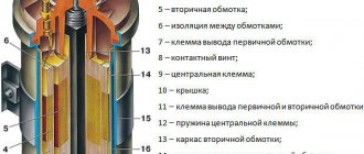
The serviceability of the ignition coil is manifested in its ability to induce the required voltage without interruptions (skips). As a rule, a faulty coil makes itself known by a characteristic decrease in the quality of operation of all eight cylinders. If it is determined that the coil is faulty, then it must be replaced with one of the same type, with the same markings. This GAZ 53 part consists of two windings: primary and secondary. The latter contains many more turns than the first. The windings are wound one on top of the other on a magnetic core. The entire structure is housed in a sealed housing filled with plastic. The malfunction of this part is associated with a short circuit, which can be interturn and to the housing.
The ignition system of the GAZ 53 car will not work efficiently if the shape of the commutator pulses entering the primary winding of the coil is incorrect. The rate at which the current decreases depends on the amplitude and shape of the primary voltage, and therefore the magnitude of the self-induction emf, which affects the spark. You can check the correctness of the pulse shape only with an oscilloscope and sample oscillogram shapes.
The quality of the high voltage circuit lies in the reliable contact of all connections, the absence of short circuits along its entire length and the required resistance value, which must be distributed in order to reduce interference from the operation of the GAZ 53 ignition system. This is possible if you follow the rules for replacing elements with new ones.
The ignition system of the GAZ 53 vehicle requires periodic inspection. It is necessary to check the quality of fit of high-voltage wires into the sockets of the coil and distributor. If there is a weakening of the contact, then you need to unbend the wire connectors and insert them into the sockets until they stop. A breakdown of the ignition coil is most likely if it is covered with a layer of dust, dirt or in water. Therefore, this should be avoided if possible. Leaving the GAZ 53 with the ignition on and the engine not running can lead to a breakdown of the coil.
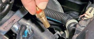
The fact is that there is always voltage in the primary winding when the ignition is on and the engine is not running, because the breaker sensor does not work. When purchasing new spark plugs, it is advisable to install those recommended by the manufacturer, having first checked the gap between the electrodes. Adjust it if necessary. Replacing elements with new ones with different markings may lead to failure of other components of the system. It is necessary to periodically lubricate the distributor shaft through the existing oiler.
Not really
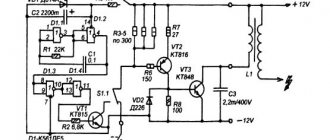
Contactless transistor ignition system GAZ-3307.
First of all, let's get acquainted with the ignition system of the GAZ-3307 truck.
The ignition system of the GAZ-3307 is battery-based, contactless transistor with a voltage in the primary circuit of 12V, consists of electric current sources, an ignition coil, an additional resistor (if I’m not mistaken, where since 2000 they have been produced without an additional resistor), a switch, an ignition distributor, spark plugs, plug tips, ignition switch and low and high voltage wires.
Technical characteristics of the ignition system of GAZ-3307 (GAZ 53) cars
Ignition order for GAZ-3307 1 — 5 — 4 — 2-6 — 3 -7 — 8
Type of ignition distributor (distributor) -
24.3706
Distributor shaft rotation speed per 1 min with uninterrupted spark formation when working with a B116 ignition coil on a three-electrode spark gap with a spark gap of 7 mm, min-1 - 20 - 2300 Direction of rotation of the ignition distributor shaft (distributor) GAZ-3307 - clockwise Ignition coil
GAZ-3307
-
B116
Spark plugs -
A11
Spark gap in spark plugs, mm - 0.8 - 0.95 Additional resistor -
14.3729
Switch -
131.3734
or
13.3734
Spark plug tip -
35.3707200
System diagram GAS ignition -3307
And so, as I already said in our time, the ignition system of the GAZ-3307 truck has undergone minor changes.
As I already wrote, this happened after 2000, this is approximately what I am saying. I can’t say for sure, I’m afraid I’ll make a mistake, but I didn’t bother googling and searching for it; I just don’t have time for it and it’s not particularly interesting. If you are interested, look for it and then share it with me. You can leave a comment.
This applies to transistor switch brands 13.3734 and 131.3734
You can see the difference is just one number, that is, it was 13.3734 before 2000, but they began to produce the GAZ-3307 after 2000 with the switch 131.3734. And so there is only one number and this is one number, that is, as you noticed, number 1 removes the additional resistor from the GAZ-3307 ignition system - 14.3729.
That is, simply put, the function of the additional resistor is 14.3729.
built into
the transistor switch 131.3734.
I want to warn you, someone may say “yes, I put brand 13.3734 instead of brand 131.3734 and why doesn’t the machine work?” I agree with him.
GAZ-3307 will of course work and go normally, but not far. Why, you ask, of course, and you’ll be right, you need to find out why
? Yes, because your ignition coil (bobbin) will simply burn out.
Why will this happen
: The ignition coil, GAZ-3307 (B 116) is a transformer, on the iron core of which the secondary winding is wound, and on top of it is the primary winding. The core with windings is installed in a sealed steel case filled with oil and closed with a high-voltage plastic cover.
Operating temperature from -50° C to +80° C. Resistance value at a temperature of 25° C: primary winding (0.65+0.07) Ohm, secondary winding (18+1.8) kOhm.
Developed secondary voltage 18 kV max. Supply voltage 12 V. Weight 0.95 kg. When operating the ignition coil B-116,
the additional resistor is 14.3729
. The resistor heats up during operation, this is normal. The resistor, when the starter is turned on (when starting the engine), is bypassed and the coil is supplied with full voltage (more precisely, the on-board voltage drawn by the starter), this makes starting easier.
the additional resistor-14.3729 takes up “work” again
.
And now give yourself this picture of a GAZ-3307, well, let’s say after the year 2000, there is, of course, ignition without an additional resistor - 14.3729
and
an ignition coil B-116
and
a transistor switch 131.3734,
and you took and installed
a transistor switch 13.3734,
and what next GAZ-3307 Of course, it will start; moreover, it will drive normally (as I already stated above), but the coil will not burn out very far. That is, there is no one to lower the on-board voltage for the ignition coil.
And as we already know, the B-116 ignition coil
is powered by a reduced voltage through
an additional resistor-14.3729
or with an added voltage reduction function in
a transistor switch brand 131.3734.
And in the consequences of the B-116 ignition coil
it will just burn out.
I still can’t help but note this moment. There is also a B-114 ignition
As you noticed, it looks no different from the B-116
(some people use it), it also fits the GAZ 3307, but I personally do not advise you to use it.
GAZ-3307 will of course work (I checked it myself, I had to
drive home
B-114 ignition the B-116
burned out) If you put it on and drive it, you may not feel the difference, but in the end it will affect fuel consumption (increase )and of course the car’s traction (decreased), the engine will operate unstably.
Simply, the B-114 ignition coil
is designed for GAZ-53 with
a contact-transistor
ignition system
Connection diagram for the new ignition system. Switch 131.3734.
1. Candles; 2. Anti-interference resistance; 3. Distributor; 4. Switch; 5. Ignition coil; 6. Generator; 7. Fuse; 8. Battery; 9. Ignition switch.
Connection diagram for switch 131.3734 as part of the ignition system:
Wiring diagram for the old-style ignition system. Switch 13.3734.
1. Distributor; 2. Switch; 3. Additional resistor (variator); 4. Ignition coil.
You can familiarize yourself with the contact-transistor ignition system in this article:
Contact-transistor ignition system of GAZ-53.
And so, friends, you and I, I think, have finished familiarizing ourselves with the ignition system of the GAZ-3307 (GAZ-53) truck. If you suddenly have any questions, you can leave comments.
Now let's figure out what are the reasons for the lack of a spark.
If suddenly you haven’t found something, or you simply don’t have time to search, then I recommend reading the articles in the categories “ GAS Repair”
". I am sure you will find the answer to your question, and if not, write in the comments the question you are interested in, I will definitely answer.
Installing electronic ignition on a car
Thus, having studied all the nuances of the work and advantages of the BSZ, it is understandable to want to equip a used car with ignition according to a similar scheme. It is logical that it will not be possible to remake the engine with the installation of numerous sensors, but every car owner can replace the contact circuit with a non-contact type.
We are preparing spare parts
At the initial stage, we prepare all the elements according to a pre-planned scheme:
- Contactless distributor. The model is selected taking into account the engine installed on the car. For example, a 1.3 liter model on a VAZ-2016 will fit with the index 38.3706-01.
- Switch. A device for interrupting the flow of current to the ignition coil.
- Ignition coil. A device for converting current from 11 volts to 20 kV for VAZ models has the index 27.3705.
- We select high-voltage wires according to size, and the type is suitable for wiring from a modern Niva.
- Spark plug. A special feature of the spark plugs will be the factory-installed gap between the electrodes of 0.7 to 0.8 mm.
Before installing all elements of contactless ignition, we be sure to prepare a set of necessary tools:
- electric drill with a drill to match the size of the screws;
- two self-tapping screws;
- Phillips screwdriver;
- a set of keys.
The procedure for carrying out installation work
To answer the question of how to install a contactless ignition system with your own hands, you should study the sequence of work using the example of a VAZ sixth series car:
- We use a previously installed breaker-distributor. We remove the cover and dismantle the high-voltage wires.
- We set the “resistor line”. By short turns of the motor we achieve the position of the resistor - perpendicular to the motor body. Further rotation of the crankshaft is not allowed.
- We make a mark for the placement of the distributor. On the engine body we apply a stroke opposite the middle mark of the ignition angle adjustment device.
- We are dismantling the previously installed breaker-distributor. We disconnect it from the ignition coil and at the place of installation on the engine.
- We install the purchased contactless distributor. We remove the top cover and place it in the nest, taking into account the previously installed mark, and secure it. The device must be adjusted in advance.
- We are replacing the ignition coil in place of the previously installed device. We connect the power wires.
- We place all the wires in their places - high-voltage wires to the spark plugs, the wire between the distributor and the coil.
- We install the switch. To do this, we drill holes for fastening in the free area of the engine compartment, and after placement, we include them in the overall scheme.
- Before starting the engine, check again that the connection is correct in accordance with the diagram. It is easy to do it yourself or find it included in the equipment package.
https://youtube.com/watch?v=NbtcE2rEgPQ
Contactless ignition faults
The following malfunctions of the contactless ignition of the VAZ 2106 are encountered, which are summarized in the table below.
| break in the sensor and TC circuit | check wiring |
| Proximity sensor does not function | check the gadget |
| lack of contact in the wiring at the TK-bobbin or TK-switch section | check wiring and connections |
| TC doesn't work | check the TC using an oscilloscope or other similar electronic measuring device, replace if necessary |
| Lost ignition switch contact | test the contact group, replace if necessary |
| defect or weak contact of the carbon | check the product |
| defects in the cover or slider of the distribution sensor | check products and replace if necessary |
| faulty resistance in the slider | update part |
| bobbin defect | update part |
| oil on the spark plug electrodes or the required gap is not set | cleaning and adjusting spark plugs |
| insulator defects | replacing spark plugs |
| violation of the high-voltage wiring connection diagram | restore the circuit |
| incorrect ignition installation | install ignition |
| Unstable engine operation or idle speed not set | set correctly |
| increased distance between spark plug electrodes | set correctly |
| low spring stiffness of the control plumbs in the sensor | replacing springs, testing the centrifugal type regulator on a special stand |