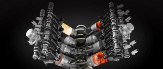
Moving parts of the crankshaft
Piston group
The piston group forms the movable wall of the working volume of the cylinder. It is the movement of this “wall”, i.e. the piston, that is an indicator of the work done by the burned and expanding gases. The piston group of the crank mechanism includes a piston, piston rings (compression and oil scraper), a piston pin and its fixing parts. Sometimes the piston group is considered together with the cylinder and is called the cylinder-piston group.
***
Piston
Requirements for piston design
The piston perceives the force of gas pressure and transmits it through the piston pin to the connecting rod. At the same time, it performs a rectilinear reciprocating motion.
Conditions under which the piston operates:
- high gas pressure (3.5...5.5 MPa for gasoline, and 6.0...15.0 MPa for diesel engines);
- contact with hot gases (up to 2600 ˚С);
- movement with changes in direction and speed.
The reciprocating movement of the piston causes significant inertial loads in the dead spot areas where the piston reverses its direction of movement. Inertial forces depend on the speed of movement of the piston and its mass.
The piston absorbs significant forces: more than 40 kN in gasoline engines, and 20 kN in diesel engines. Contact with hot gases causes the central part of the piston to heat up to a temperature of 300...350 ˚С. Strong heating of the piston is dangerous due to the possibility of jamming in the cylinder due to thermal expansion, and even burning out of the piston bottom.
The movement of the piston is accompanied by increased friction and, as a consequence, wear of its surface and the surface of the cylinder (liner). During the movement of the piston from top dead center to bottom and back, the pressure force of the piston surface on the surface of the cylinder (liner) changes both in magnitude and direction depending on the stroke occurring in the cylinder.
The piston exerts maximum pressure on the cylinder wall during the power stroke, at the moment when the connecting rod begins to deviate from the piston axis. In this case, the gas pressure force transmitted by the piston to the connecting rod causes a reaction force in the piston pin, which in this case is a cylindrical hinge. This reaction is directed from the piston pin along the line of the connecting rod, and can be decomposed into two components - one is directed along the piston axis, the second (lateral force) is perpendicular to it and directed normal to the cylinder surface.
It is this (lateral) force that causes significant friction between the surfaces of the piston and cylinder (liner), leading to their wear, additional heating of parts and a decrease in efficiency due to energy losses.
Attempts to reduce the friction forces between the piston and the cylinder walls are complicated by the fact that a minimum gap is required between the cylinder and the piston to ensure complete sealing of the working cavity in order to prevent gas breakthrough, as well as oil from entering the working space of the cylinder. The size of the gap between the piston and the cylinder surface is limited by the thermal expansion of the parts. If it is made too small to meet sealing requirements, the piston may jam in the cylinder due to thermal expansion.
When the direction of movement of the piston and the processes (cycles) occurring in the cylinder change, the friction force of the piston on the cylinder walls changes in nature - the piston is pressed against the opposite wall of the cylinder, while in the transition zone of the dead points the piston strikes the cylinder due to a sharp change in the magnitude and load directions.
When developing engines, designers have to solve a complex of problems associated with the operating conditions of the cylinder-piston group parts described above:
- high thermal loads, causing thermal expansion and corrosion of the metals of the crankshaft parts;
- colossal pressure and inertial loads that can destroy parts and their connections;
- significant frictional forces causing additional heating, wear and energy loss.
Based on this, the following requirements are imposed on the piston design:
- sufficient rigidity to withstand force loads;
- thermal resistance and minimal temperature deformation;
- minimum mass to reduce inertial loads, while the mass of the pistons in multi-cylinder engines should be the same;
- ensuring a high degree of sealing of the working cavity of the cylinder;
- minimal friction on the cylinder walls;
- high durability, since replacing pistons involves labor-intensive repair operations.
***
Piston design features
The pistons of modern automobile engines have a complex spatial shape, which is determined by various factors and conditions in which this important part operates. Many elements and features of the piston shape are not noticeable to the naked eye, since deviations from cylindricity and symmetry are minimal, however, they are present. Let's take a closer look at how the piston of an internal combustion engine works, and what tricks designers have to go to in order to ensure that the requirements set out above are met.
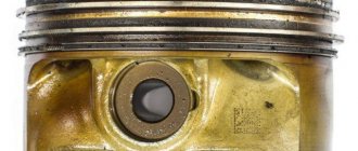
The piston of an internal combustion engine consists of an upper part - the head and a lower part - the skirt.
The upper part of the piston head - the bottom - directly perceives the forces from the working gases. In gasoline engines, the piston crown is usually made flat. The piston heads of diesel engines often contain a combustion chamber.
The piston bottom is a massive disk, which is connected by means of ribs or struts to bosses that have holes for the piston pin - bosses. The inner surface of the piston is made in the form of an arch, which provides the necessary rigidity and heat dissipation.
***
Grooves for piston rings are cut on the side surface of the piston. The number of piston rings depends on the gas pressure and the average speed of the piston (i.e., the engine speed) - the lower the average piston speed, the more rings are required. In modern engines, along with an increase in crankshaft speed, there is a tendency to reduce the number of compression rings on the pistons. This is due to the need to reduce the mass of the piston in order to reduce inertial loads, as well as reduce friction forces, which take up a significant share of engine power. At the same time, the possibility of gas breakthrough into the crankcase of a high-speed engine is considered a less pressing problem. Therefore, in the engines of modern passenger cars and racing cars you can find designs with one compression ring on the piston, and the pistons themselves have a shortened skirt.
In addition to compression rings, one or two oil scraper rings are installed on the piston. The grooves made in the piston for the oil scraper rings have drainage holes to drain engine oil into the internal cavity of the piston when the ring removes it from the surface of the cylinder (liner). This oil is typically used to cool the inside of the piston crown and skirt and then drains into the oil pan.
The shape of the piston crown depends on the type of engine, the method of mixture formation and the shape of the combustion chamber. The most common flat bottom shape, although convex and concave are also found. In some cases, recesses are made in the piston bottom for valve discs when the piston is located at top dead center (TDC). As mentioned above, the piston heads of diesel engines often contain combustion chambers, the shape of which can vary.
The lower part of the piston - the skirt - guides the piston in a linear motion, while it transmits a lateral force to the cylinder wall, the magnitude of which depends on the position of the piston and the processes occurring in the working cavity of the cylinder. The magnitude of the lateral force transmitted by the piston skirt is significantly less than the maximum force perceived by the bottom from the gas side, so the skirt is made relatively thin-walled.
A second oil scraper ring is often installed in the lower part of the skirt on diesel engines, which improves cylinder lubrication and reduces the likelihood of oil getting into the working cavity of the cylinder. To reduce the piston mass and friction forces, the unloaded parts of the skirt are cut off in diameter and shortened in height. Technological bosses are usually made inside the skirt, which are used to adjust the pistons according to mass.
The design and dimensions of the pistons depend mainly on the speed of the engine, as well as on the magnitude and rate of increase in gas pressure. Thus, the pistons of high-speed gasoline engines are as lightweight as possible, while the pistons of diesel engines have a more massive and rigid design.
At the moment the piston passes through TDC, the direction of action of the lateral force, which is one of the components of the gas pressure force on the piston, changes. As a result, the piston moves from one cylinder wall to another - the piston shifts. This causes the piston to hit the cylinder wall, accompanied by a characteristic knocking sound. To reduce this harmful phenomenon, the piston pins are shifted by 2...3 mm in the direction of the maximum lateral force; in this case, the lateral pressure force of the piston on the cylinder is significantly reduced. This displacement of the piston pin is called desaxing. The use of desaxing piston in the design requires compliance with the installation rules of the crankshaft drive - the piston must be installed strictly according to the marks indicating where the front part is (usually an arrow on the bottom).
An original solution designed to reduce the impact of lateral forces was used by engine designers. The piston bottom in such engines is not made at a right angle to the cylinder axis, but is slightly beveled. According to the designers, this makes it possible to optimally distribute the load on the piston and improve the process of mixture formation in the cylinder during the intake and compression strokes.
In order to satisfy the conflicting requirements for the tightness of the working cavity, which require the presence of minimal clearances between the piston skirt and the cylinder, and to prevent jamming of the part as a result of thermal expansion, the following structural elements are used in the shape of the piston:
- reducing the rigidity of the skirt due to special slots that compensate for its thermal expansion and improve cooling of the lower part of the piston. The slots are made on the side of the skirt that is least loaded with lateral forces pressing the piston to the cylinder;
- forced limitation of thermal expansion of the skirt by inserts made of materials with a lower coefficient of thermal expansion than the base metal;
- giving the piston skirt such a shape that, when loaded and at operating temperature, it takes the shape of a regular cylinder.
The last condition is not easy to fulfill, since the piston is heated unevenly throughout the entire volume and has a complex spatial shape - in the upper part its shape is symmetrical, but in the area of the bosses and on the lower part of the skirt there are asymmetrical elements. All this leads to unequal temperature deformation of individual sections of the piston when it is heated during operation. For these reasons, the piston design of modern automobile engines usually includes the following elements that complicate its shape:
- the piston bottom has a smaller diameter compared to the skirt and is closest in cross section to a regular circle. The smaller cross-sectional diameter of the piston crown is associated with its high operating temperature and, as a result, with greater thermal expansion than in the skirt area. Therefore, the piston of a modern engine in longitudinal section has a slightly conical or barrel-shaped shape, narrowed towards the bottom. The reduction in diameter in the upper zone of the conical skirt for pistons made of aluminum alloy is 0.0003...0.0005D, where D is the cylinder diameter. When heated to operating temperatures, the shape of the piston along its length is “evened out” to the correct cylinder.
- in the area of the bosses, the piston has smaller transverse dimensions, since masses of metal are concentrated here, and thermal expansion is greater. Therefore, the piston below the bottom has an oval or elliptical cross-section, which, when the part is heated to operating temperatures, approaches the shape of a regular circle, and the piston in shape approaches a regular cylinder. The major axis of the oval is located in a plane perpendicular to the axis of the piston pin. The ovality value ranges from 0.182 to 0.8 mm.
Obviously, designers have to go to all these tricks to give the piston the correct cylindrical shape when heated to operating temperatures, thereby ensuring a minimum gap between it and the cylinder.
The most effective way to prevent the piston from jamming in the cylinder due to its thermal expansion with a minimum clearance is to forcefully cool the skirt and insert metal elements with a low coefficient of thermal expansion into the piston skirt. Most often, low-carbon steel inserts are used in the form of transverse plates, which are placed in the boss area when casting the piston. In some cases, instead of plates, rings or half-rings are used, cast into the upper zone of the piston skirt.
The temperature of the bottom of aluminum pistons should not exceed 320...350 ˚С. Therefore, to increase heat removal, the transition from the piston bottom to the walls is made smooth (in the form of an arch) and quite massive. To more effectively remove heat from the piston bottom, it is forced to cool by spraying engine oil from a special nozzle onto the inner surface of the piston bottom. Typically, the function of such a nozzle is performed by a special calibrated hole made in the upper head of the connecting rod. Sometimes the injector is installed on the engine body at the bottom of the cylinder.
To ensure normal thermal conditions of the upper compression ring, it is located significantly below the edge of the bottom, forming a so-called heat or fire belt. The most worn ends of the groove for the piston rings are often reinforced with special inserts made of wear-resistant material.
Aluminum alloys are widely used as a material for the manufacture of pistons, the main advantage of which is their low weight and good thermal conductivity. The disadvantages of aluminum alloys include low fatigue strength, high coefficient of thermal expansion, insufficient wear resistance and relatively high cost.
In addition to aluminum, the alloys contain silicon (11...25%) and additives of sodium, nitrogen, phosphorus, nickel, chromium, magnesium and copper. Cast or stamped blanks are subjected to mechanical and heat treatment.
Cast iron is used much less frequently as a material for pistons, since this metal is much cheaper and stronger than aluminum. But, despite its high strength and wear resistance, cast iron has a relatively large mass, which leads to the appearance of significant inertial loads, especially when the direction of piston movement changes. Therefore, cast iron is not used for the manufacture of high-speed engine pistons.
***
Purpose and types of piston rings
Home page
- Applicant's page
Distance education
- Group TO-81
- Group M-81
- Group TO-71
Specialties
- Veterinary
- Agricultural mechanization
- Commerce
- Vehicle maintenance and repair
Academic disciplines
- Engineering graphics
- MDK.01.01. "Car design"
- Section map
- General structure of the car
- car engine
- Car transmission
- Steering
- Brake system
- Suspension
- Wheels
- Body
- Car electrical equipment
- Basic car theory
- Basics of technical diagnostics
- Fundamentals of hydraulics and heat engineering
- Metrology and standardization
- Agreecultural machines. Agreecultural equipment
- Basics of agronomy
- Transportation of dangerous goods
- Materials Science
- Management
- Technical mechanics
- Tips for graduate student
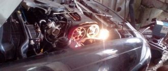
Troubleshooting
There are several characteristic features and signs, when it comes to car engines, that indicate failure or wear of the displacer.
This may manifest itself as the following symptoms:
- starting the engine is difficult;
- after starting the engine, floating speed is observed;
- the engine is running unsteadily;
- The internal combustion engine may start to stall;
- the noise level during operation increases, which was not previously observed;
- in some cases, you may notice a knocking sound of the plunger when the fuel pump is running;
- working under load, the power of the power unit decreases;
- the movement of the car is accompanied by noticeable jerks;
- In some situations, the engine completely breaks down.
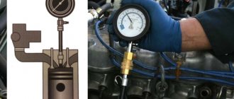
To check the plunger as part of a high-pressure pump, special equipment is required. With its help you can find out how much the displacer and bushing have worn out.
There are two ways to restore the operation of the injection pump:
- perform a complete replacement of worn out and failed components;
- repair parts.
The essence of the repair is to restore the exact fit, to ensure the required clearance to the required factory parameters. But doing this in a garage will be extremely problematic. You will have to contact a car service.