Ignition system switches
Purpose and principle of operation of the ignition system switch
In the ignition system of automobile engines, to produce a high voltage current that causes sparking on the electrodes of the spark plugs, the principle of electromagnetic induction is used - the ignition coil, which is a kind of transformer, is capable of converting the voltage of the vehicle's on-board circuit (12 V) into a voltage reaching several thousand volts.
To do this, it is necessary to periodically apply and disconnect current from the primary circuit of the ignition coil, as a result of which the direct current of the on-board circuit becomes variable (cyclically varying in value from zero to 12 V and vice versa). The first engine ignition systems used devices (breakers) for these purposes that open and close electrical contacts mechanically. In principle, these devices can be called the ancestors of modern switches for automotive ignition systems. However, mechanical (contact) switches had a number of significant shortcomings, which became more and more obvious as automobile engines developed and improved. The contacts were prone to burning, required systematic cleaning and gap adjustment, and could not “boast” of the stability of the generated impulse in terms of magnitude and duration. In addition, they had noticeable inertia, like all mechanical devices, which limited the capabilities of high-speed engines, and an insufficiently long and powerful spark was a stumbling block to increasing the compression ratio. However, such ignition systems have been used in cars for a long time, and only the advent and improvement of semiconductor devices allowed designers to make a kind of revolution in the method of switching control pulses.
At first, the designers did not abandon the use of mechanical contacts of the breaker, but they solved the problem with their electrical load, which leads to burning. A weak control current was passed through the contacts of the breaker, which was supplied to the base of a powerful transistor, which served as an amplifier of the signal entering the primary circuit of the ignition coil. This is how contact-transistor ignition systems and the first semiconductor switches appeared. Subsequently, designers of ignition systems abandoned mechanical contacts, using various magnetoelectric sensors, as well as sensors operating on the Hall effect, to form a low-power pulse. The improvement of these devices continues to this day, while modern switches of automotive ignition systems are completely different from their mechanical and even transistor “ancestors”.
The use of semiconductor and microprocessor switches in contact-transistor or contactless ignition systems allows you to obtain the following advantages:
- the current flowing through the contacts of the breaker decreases, as a result of which they practically stop burning (for a contact-transistor ignition system);
- the duration of the spark supply increases, which guarantees effective ignition of the working mixture in the engine cylinders;
- it becomes possible to significantly increase the compression ratio in the engine cylinders, as well as the crankshaft rotation speed, without compromising the reliability of spark formation.
In general, the reliability of the ignition system is increased and the complexity of its maintenance is reduced.
Manufactured switches for contact-transistor and contactless ignition systems are divided into three groups:
- switches based on discrete semiconductor components using packaged integrated circuits mounted on printed circuit boards;
- switches made using thick film technology using standard bulk and discrete components;
- switches manufactured using hybrid technology using a special solid-state microcircuit on which the main functional components of the switch are implemented.
Switches for contact-transistor ignition systems
Switches of contact-transistor systems and switches with a constant duty cycle of output current pulses for contactless ignition systems are functionally simple and contain a small number of semiconductor components (usually no more than four transistors). They belong to the first group. They are based on a cast aluminum housing with a ribbed outer surface to improve heat transfer. All elements of the switch are located inside the case with the exception of the output transistor, which is mounted on the case in a special pocket.
Many types of transistors (for example, npn) require insulation from the switch body, so they are mounted through a special gasket. To reduce the thermal resistance of the junction between the switch body and the gasket, thermally conductive pastes are applied, due to which the cooling of the output transistor is more intense. A terminal block is used to connect the switch to the vehicle’s on-board network and to the elements of the ignition system.
Switch TK102
In Fig. 1 shows the TK102 switch, which belongs to the first group, which is designed to work in the contact-transistor ignition system of cars with eight-cylinder engines, but can be used to work with any classic ignition distributor. Coil B114 is used as a load (W2/W1 = 235; L1 = 3.7 mH; R1 = 0.42 Ohm). To limit the primary current, an additional resistance SE107 (1.04 Ohm) is used. The TK102 switch has one powerful germanium transistor GT701A (VT1), a zener diode D817V (VD2) and a diode D7Zh (VD1), which serve to protect the power transistor VT1 from overvoltage. Choke L1 and resistor R1 are designed to speed up the process of closing transistor VT1, capacitor C1 of the primary excitation circuit of the ignition coil and capacitor C2 serve to protect the components of the switch circuit from voltage surges in the vehicle's on-board network. In the event of a switch failure (for example, if a transistor fails), the wires can be moved to the standard position, and the engine will continue to operate, allowing the driver to get to the repair site.
Switches for contactless ignition systems
Switches of this type are used in ignition systems, where magnetoelectric sensors, rather than mechanically controlled contacts, are used to generate a current control pulse in the primary circuit of the ignition coil.
Electronic switches of contactless ignition systems perform the following functions:
- generating an output current pulse of the required amplitude and duration supplied to the primary winding of the ignition coil (or coils) to provide a given level of high voltage and spark energy;
- ensuring the moment of spark formation in accordance with the specified edge of the control pulse arriving at the input of the switch;
- stabilization of the parameters of the output current pulse during fluctuations in the voltage of the vehicle’s on-board network and the influence of external factors.
Various switches can perform additional functions:
- stabilization of power supply and protection against overvoltage pulses in the vehicle’s on-board network in abnormal modes of a microswitch operating on the Hall effect;
- limiting the amplitude of the secondary voltage pulse in abnormal modes (for example, in open circuit mode);
- preventing the flow of primary current through the primary winding of the ignition coil when the ignition switch is on and the engine is not running.
The input terminals of the switch receive control pulses generated by a non-contact sensor of the angular position of the engine crankshaft or an electronic voltage regulator - a collector. The output (load) of the commutator is the primary winding of the ignition coil (or coils). In the case when the commutator serves two or more coils, it serves as a distributor of high-voltage pulses across the engine cylinders.
Contactless switch of three-phase circuits
) Declared on 18.07 21) 2048051/24 03 By 17/5 by joining the application M23) Priority of the State Administration of the USSR PV dalem iaobreeal in etkrlvy) CONTACTLESS SWITCH OF THREE-PHASE CIRCUITS ation.
The purpose is to increase the hope of achieving construction. The invention relates to electrical engineering, namely to devices used for turning on and off electrical installations powered by alternating current. Thyristors are widely used as the executive body of contactless switches. Control devices are known that do not have a galvanic connection with the control electrodes of thyristors, in which for control thyristors use peaked pulses with a frequency exceeding the frequency of the switching voltage 11. The disadvantage of this circuit is that the control pulse in them does not always coincide with the beginning of the half-cycle of the switching voltage (thyristors can operate with a cutoff), and an additional power source is required for the pulse generator. The closest in The technical essence of the proposed invention is a switch containing an executive element, which is a symmetrical thyristor, two transformers and a control unit on back-to-back diodes and transistor 2. The disadvantage of this device is that the windings of the transformers shunt the transistor. This leads to the fact that the current no-load circuit of transformers flows through the load and therefore the voltage from the load is not completely removed, i.e. the reliability of the switch is reduced. The goal is achieved by the fact that in a contactless switch of three-phase circuits containing an actuator, two transformers, a control unit on back-to-back diodes and a transistor and diode resistor chains, the actuator is made on back-to-back parallel connected thyristors and diodes, the transformers are made of three-phase, and The primary switching is carried out by igniting the ios 1 y current or by closing l 1 low-power contact. The switch can be used in three-phase high-power and low-power computers with any load connection scheme. The present invention differs favorably from known devices in its simplicity and reliability in operation, does not require an additional 11 power source, allows the use of a low-power control signal, does not have a galvanic connection of the control circuit with the switched circuit 15 formula of invention Contactless switch of three-phase circuits containing an actuator, 2 O two transformers, a control unit on back-to-back diodes and a transistor and diode resistor chains, O and The main point is that, in order to increase reliability, the executive25organ is made on back-to-back parallel-connected thyristors and diodes, the transformers are made three-phase, and the primary windings of one three-phase transformer are connected in a triangle and connected to the input of the switch, the secondary windings are connected in a star and connected to the beginnings of the primary windings of another three-phase transformer, the ends of these pads are connected to the common points of back-to-back diodes of the control unit, the end of the secondary winding of phase A of the second three-phase transformer is connected through a diode-resistor chain to the control electrode of the thyristor of phase C of the executive body, in a similar way the end of the secondary winding of phase B is connected to the control electrode of the thyristor phase A, the end of the secondary winding of phase C is connected to the control electrode of the thyristor of phase B, and the beginnings of these windings are connected to the output of the commutator. Sources of information taken into account during the examination1. Federal Republic of Germany patent No. 1230848, class, 21 b 36/18, 1964.2. Dzyubin I. I. Thyristogy in electrical circuits. M., Energy, 1972, p. 40, fig. 24. 3 678667ki of one three-phase transformer are connected in a triangle and connected to the input of the switch, the secondary windings are connected in a star and connected to the beginning of the primary windings of another three-phase transformer, the ends of which are connected to the common points of back-to-back diodes of the control unit, the end of the secondary winding of phase A of the second three-phase transformer is connected through a diode - a resistor chain with the control electrode of the thyristor of phase C of the executive body, similarly, the end of the secondary winding of phase B is connected to the control electrode of the thyristor of phase A, the end of the secondary winding of phase is connected to the control electrode of the thyristor of phase B, and the beginnings of these windings are connected to the output of the switch. The drawing shows electrical circuit of the switch. The switch consists of an actuator on thyristors 1, 2, 3 and diodes 4, 5, 6, two transformers 7 and 8, a control unit on transistor 9, diodes 10-15, and resistors 16, 17. The switch operates as follows. The switched three-phase voltage is supplied to the input of the switch and at the same time supplied to the primary windings of the three-phase transformer 7, connected in a triangle. The secondary windings of the transformer 7 are connected in a star. From the secondary windings of the transformer 7, voltage is supplied to the primary windings of the three-phase transformer 8, which can be connected in a star through diodes 10-15 and transistor 9, if it is open. From the secondary windings of transformer 8, voltage is supplied through diodes 18-20 and resistors 21- 23 is supplied to the control electrodes of thyristors 1, 2, 3. Thus, the thyristors are controlled by a positive zero-wave sinusoid, which advances the phase of the linear voltage on the thyristor by 60 el. degrees, which ensures that voltage is supplied to the load of the switch without cutoff. The source of thyristor control voltage is a three-phase voltage supplied to the input of the switch. The launch of the board scheme can Osu678667 Compiled by O. Parfenovabov Tehred N, Baburka Proofreader M. Pozho actor Dln ts PPP “Patent”, Uzhgorod, st. Design, Order 4581/48TSCIPIpo de113035, Circulation 1060 Subscribed by the USSR State Committee for Inventions and DiscoveriesMoscow, Zh, Raushskaya embankment, 4/ View
Controllers
Controllers of the MS2715.03 series for VAZ-21083 passenger cars and MS2713.01 for ZIL-4314 trucks are produced, designed to control the ignition timing according to the optimal control characteristic based on information from reference sensors, engine speed, throttle vacuum carburetor space (or intake pipe of an injection engine) and coolant temperature.
The controllers also control the electrovalve of the forced idle economizer (EFS). The MC2715.03 controller for passenger cars with a four-stroke four-cylinder engine generates a “Channel Select” signal to provide the function of static energy distribution among the engine cylinders.
The block diagram of the controller is shown in Fig. 6. The controller outputs receive signals from the reference sensor (HO), the angular pulse sensor (AP), the crankshaft speed sensor (CV), the vacuum sensor (P), and the coolant temperature sensor (Tohl).
After processing the sensor signals in an analog-to-digital converter (ADC), information about engine parameters in the form of digital codes enters the processor, which calculates the engine speed, vacuum, temperature, angular position of the engine crankshaft and, based on these data, calculates the advance angle ignition in accordance with the engine ignition timing map, which is stored in the processor memory. Synchronization of the controller operation with the engine operation and generation of the “Channel Selection” signal is carried out using pulses from the NO sensor. The output signals of the processor control the operation of the ignition pulse shapers (IPD) and the selection of the EPHH amplifier channel. The signals PHYS and VK directly control the operation of a two-channel switch.
A characteristic feature of the car can be considered its rapid obsolescence, but long life. The most modern car today, in at least two years, will be inferior to other, newer cars with improved characteristics. But even now there are cars from the last century on the roads. Therefore, it is not just interesting, but sometimes necessary, to know at least in general terms what such vehicles are, their structure, features, including such a thing as a simple ignition switch, which significantly changed the capabilities of the car.
What is and what is the principle of operation of the ignition switch
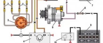
Even on the very first cars, battery ignition systems were used to ignite the combustible mixture, the functional diagram of which is shown in the figure.
This figure allows you to understand that its work is based on the principle of self-induction. When the current flow circuit in the winding of bobbin 3 is broken, a high-voltage EMF is induced in the secondary, causing a spark to appear on the contacts of spark plug 2. The circuit break is caused by the opening of the contacts of breaker 6.
Without touching on the advantages or disadvantages, it should be noted that this scheme worked on the car for a long time. And only the emergence of a new element base gave impetus to the further development of such a device, preserving the original principle of its operation.
Contactless current switch
Performs the same functions as the TSh-5 relay.
The BKT circuit includes two power diodes VD1 and VD2, isolation diodes VD3 and VD4 in the thyristor control circuits, resistors R1 and R2 connected in parallel to the thyristor inputs, and a nonlinear resistance (varistor) R3.
Diode VD1 and thyristor VS1 are connected back-to-back and in parallel. They form an asymmetrical AC switch. Diode VD2 and thyristor VS2 form a similar switch.
Both keys are connected in series with each other and have a midpoint (pin 33).
The conclusion of the BKT is conclusions 11(12) and 71(72).
Resistors R1 and R2 stabilize the operation of the circuit when the ambient temperature changes and the deviation of the thyristor control currents.
Varistor R3 is used to protect diodes from breakdown when exposed to pulsed noise of higher amplitude.
When the control circuit is open (pins 33 and 53), thyristors VS1 and VS2 are locked. Alternating current does not flow between pins 11 and 71, because The thyristors are connected back-to-back.
When the control circuit of the relay contact T (pin 33,53) and the positive and negative half-waves of the alternating current are closed, the thyristors VS1 and VS2 open alternately, and the alternating current begins to pass through them.
If instantaneous positive polarity from T is applied to pin 11, then a control circuit occurs.
Thyristors VS2: lower terminal of thyristor T, pin 53, diode VD4, pins 51 and 52, control diode of thyristor VS2, cathode VS2, pins 71 and 72, load (DT), reactor L, upper terminal of the winding of thyristor T.
When the control current reaches the value of the unlocking current, the thyristor VS2 opens and, together with the diode VD1, passes the load current through the circuit: winding of tr-ra T, pin 11, diode VD1, thyristor VS2, pins 71 and 72, load, reactor L, upper terminal of tr- ra T.
With a negative half-wave of alternating current, a similar circuit is created to control the thyristor VS1 (TL - load, 71(72)-VD2-33/53-VD3-31/32-VS1-11/12-T), it opens together with the diode VD2 to form through the load the operating circuit for the negative half-wave of alternating current. Thus, while the control circuit (33/53) is closed, the thyristors open one by one, passing alternating current through the inductor-tr-p (DT).
After contact T is opened, the thyristor control circuits are opened; when the load current passes through “0,” the thyristors close and remain locked until the next time the relay contact control circuit T is closed.
Non-contact parametric relay.
The principle of its operation is based on the property of exciting oscillations in the circuit by periodically changing its parameters (L or C). More often, non-contact parametric relays are used, in which the inductance changes under the influence of the input signal.
The inductance of the circuit (winding W3) changes when current flows through the excitation windings W1 and W2, which are connected in opposite directions to prevent direct transformation of the current to the output winding W3. When a current is excited with a frequency f, the inductance of the parametric circuit changes twice per period (from positive and negative half-waves), i.e. with a frequency of 2f, oscillations are also excited in the circuit with a frequency of 2f. Parametric excitations increase in an avalanche-like (jump-like) manner when the input signal reaches a certain value. If the input signal is reduced to a certain level, the oscillations stop. This property allows such a circuit to be used as a parametric relay.
Return rate
where Uin. and Uin.av. - corresponds to the actuation and release voltage (termination of generation of the contactless relay).
The relay operates under the influence of current supplied to the input of the DC. In this respect it is similar to a contact track relay.
Disadvantages: limited operating range (due to oversaturation of the core), the ability to operate in transformer mode when one of the input windings is short-circuited, which is unacceptable.
Relay element based on a tunnel diode.
The current-voltage characteristic of a tunnel diode has three regions.
Region A corresponds to the flow of tunnel current. Region B is the negative resistance region.
As the voltage U>Umax increases, the number of electrons capable of making a tunnel transition decreases, and the current sharply decreases. When U=Umin the tunnel current disappears. In region C, the normal diffusion current of the diode increases.
The relay circuit based on a tunnel diode has 2 stable states, determined by points 1 and 2 of the load characteristic.
In the initial state (iin=0), the tunnel diode is open (point 1), and current I1 flows through the load (relay on). When a pulse of positive polarity is applied to the input of the circuit, the voltage on the diode increases to the value Umax, and the diode closes. The load current abruptly decreases to I2 (point 2).
The relay turns off. To turn on the diode, a pulse of negative polarity is applied to the input of the circuit. This causes the voltage across the diode to decrease to Umin, and the current in the load increases abruptly to the value I1 (point 1).
The advantage of tunnel diodes is their high operating frequency (tens of MHz), since the tunnel transition of electrons occurs almost instantly in a time = seconds.
The disadvantage of tunnel diodes is the absence of an input electrode, which causes difficulties when connecting diodes to each other in circuits. Therefore, transistor-diode relay elements are often used
In them, a tunnel diode is used to store information, and a transistor is used to amplify signals.
What could the ignition system switch look like?
The above switch circuit is just one of the options for how the ignition device can be implemented. This is done using:
- transistors;
- thyristors:
- hybrid elements;
- contactless sensors.
The transistor circuit of the switch is discussed above; the thyristor circuit uses energy accumulation in the capacitor, and not in the electromagnetic field of the ignition coil. During operation of the thyristor system, when control signals are received, the circuit connects a charged capacitor to the windings of the coil, through which it is discharged, causing a spark to appear. Without touching on the advantages and disadvantages that this or that circuit has, suffice it to say that any such device provides a significant improvement in all parameters of the ignition system, and the switch over time has replaced conventional battery ignition.
However, it is necessary to note one more stage in the development of the system, and the switch in particular. The use of electronic components and the introduction of a switch into the design of the car made it possible over time to abandon the contact voltage breaker and replace it with a contactless sensor. Such a system, in domestic cars, was first used in VAZ cars, in particular the VAZ 2108. A similar operating principle, when the switch receives signals from a special unit, is implemented on the VAZ 2108 using a Hall sensor.
When considering the options for what the switch device could be, one cannot ignore the development of the ignition system itself. The main principle that is implemented during its construction is to increase the reliability and efficiency of the entire system. This is achieved by using microprocessor systems that use the readings of numerous sensors. To work with such systems, you need at least a two-channel switch, and recently a separate coil and switch for each spark plug. This approach – a two-channel switch (later also multi-channel) allows you to provide:
- more powerful spark;
- elimination of losses in the distributor;
- stable idle;
- improved starting at low temperatures;
- reduction in fuel consumption.
It is worth noting that a two-channel switch allows you to get rid of the slider.