Diode bridge functions
For charging and normal operation of the battery, direct current is required, but the generator produces only alternating current. To make the desired conversion, a diode bridge is used. The electronic components included in this unit conduct current in only one direction, rectifying it. The resulting voltage drops are smoothed out by the battery, “replacing” the capacitor. The functions of valves are most often performed by silicon diodes. However, it is possible to use other types of rectifiers - for example, selenium pillars.
Symptoms of a problem
The block is equipped with 6 diodes. Failure of even one of them “guarantees” the formation of voltage dips, which begin to deviate from the norm. At the same time, electromagnetic interference is generated. How to determine that the diode bridge of the generator is not working? Main symptoms:
- rapid discharge of the battery (the corresponding lamp on the dashboard flashes or stays on after the engine starts);
- the battery is recharged, leading to boiling off of the electrolyte;
- when driving, the headlights shine dimly;
- The power of the cabin “stove” and air conditioning is clearly not enough;
- The media system operates with distortion.
Failure of the diode bridge most often occurs due to water getting inside the generator (do not recklessly force deep puddles!). There is also a possible reason such as incorrect connection of the plus and minus when starting the engine using the “lighting” method.
How to check a generator diode bridge
Test the unit on an installed or removed generator. To carry out the procedure, you will need wires and an ohmmeter, but an ordinary car light bulb will do.
Checking the diode bridge on a car
Before testing, remove the negative terminal from the battery and disconnect the wires from the generator. If you are using a multimeter, set it to ohmmeter mode. Touch the positive red probe to terminal “30” of the generator, and the negative probe to the metal body of the generator. If the rectifier unit is working properly, the device readings will show an infinitely high resistance. Otherwise, the diode bridge must be replaced.
The above test allows you to determine the integrity of the bridge in terms of the absence of a short circuit. At the next stage, the element is checked for breakdown. Using the red positive probe, touch terminal “30” of the generator again, and the negative probe, in turn, touch the axle mounting bolts (usually they are square). The resistance must be infinitely large. Now swap the probes: the readings should be 500-700 Ohms. You need to check each diode separately, changing the polarity of the tester!
If you don't have a meter, use a 12V car light bulb. Then disconnect all the terminals from the battery and the wires from the generator. First you need to test the entire bridge:
- connect the minus battery to the metal housing of the generator;
- take a suitable wire and connect a light bulb (in series) to its gap;
- connect the other end of the wire from it to terminal “30” of the generator;
- the glow of the lamp indicates a bridge malfunction.
Next you need to test each diode. To do this, attach the minus to the housing, and touch the diode mounting bolt with the plus through the lamp. Its glow indicates a breakdown of the electronic component. Check each of them. Next, attach the “plus” coming from the battery to terminal “30” of the generator, and touch the diodes with the minus one by one. If the lamp lights up in any case, the bridge needs to be replaced. If you need to check additional diodes, leave the “plus” on terminal “30”, and connect the minus to terminal “61”: a glowing light indicates problems in the rectifier unit.
Checking the dismantled rectifier unit
Remove the generator and remove the bridge from it. Further course of action:
- set the tester to the ohmmeter position and turn on (if available) the sound indication;
- connect the negative probe of the device to the central plate, and touch the positive probe to a metal core (this can be a flat strip of metal or a bare wire);
- the device will show either infinity or 500-700 Ohms;
- swap the poles of the probes: the readings should change to the opposite;
- if the readings match, the diode is faulty;
- Do this procedure for each electronic component of the bridge.
Checking the removed bridge using a lamp
There is an opinion among some car enthusiasts that it is better to test the rectifier unit under load, using a 21W car lamp. To do this, you will need a battery and wires to create a simple electrical circuit, in which one wire is connected to the negative of the battery, the second - through the lamp (in series) to the positive. Check procedure:
- First, you should check the rectifier unit for short circuits between the plates. To do this, press the positive wire (its free end) to the top plate, and the negative wire to the bottom plate. The absence of a glow indicates that there is no short circuit. If you change the polarity of the connection, the lamp will light up.
- Now the positive elements are checked for breakdown and breakage. Press the positive wire with a crocodile to the top plate, the negative wire to each connection point of the diodes. In this case, you need to change the polarity: if the element is working, in one case the lamp will light, in the other - not.
- We do the same with the negative group of elements. But only here we attach the negative wire to the bottom plate.
- It remains to check the additional diodes. To do this, attach the positive wire to pin “61”, and the negative wire in turn to each connection point of the electronic components. Change the polarity and make sure that in one case the lamp lights up, in the other - not. If so, the diodes are good.
Rectifier design
In the literal sense, a rectifier is not able to “straighten” alternating voltage. This unit received its name because of the operating principle of the diodes included in it:
- alternating current periodically changes the direction of movement in the circuit;
- diodes pass it in only one direction and cut off currents of reverse polarity;
- so that power surges in the network are invisible to the powered consumer, 3 diodes are installed in one direction, the remaining 3 in the other.
Currently, high-power diodes have a classic design; low-power semiconductor devices of this type are made in the form of a silicon junction on a board. However, to remove high temperatures from the body or silicon junction, both modifications are either embedded in the heat sink plate or equipped with their own individual radiators.
If a silicon junction or a full-fledged diode in the housing breaks down, the diode bridge of the generator or individual semiconductors included in its composition must be replaced.
Main diode bridge
The lower figure shows sinusoids and the direction of current movement in the generator and diode bridge.
The positive value is conditionally taken to be the voltage directed to the 0 point of the stator winding. After the rectifier, the current in the consumer load flows only in the positive direction, that is, from the “+” of the generator to its mass “-”.
Therefore, the power diode bridge (main) uses large-sized 25 - 30 A diodes, the power of which can be further increased due to the additional rectifier arm discussed below.
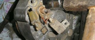
Unlike other components of the “auto power plant”, a visual inspection does not allow us to identify any faults in the diode bridge of the generator. The rectifier requires only hardware diagnostics with a multimeter.
The diodes are located on a horseshoe-shaped heat sink plate under the back cover of the generator. On remote rectifiers, the diode bridge is located near the generator; instead of plates of the classical configuration, a regular board can be used. In this case, a finned radiator is placed on the body of each diode.
Additional diodes
The main difficulty in the design of a car generator is that the excitation winding of its armature is also a consumer of constant voltage. This coil uses the generator's own diode bridge:
- 3 additional diodes cut off the battery current when the engine is not running;
- negative diodes are taken from the main (power) bridge of the generator.
Instead of powerful semiconductor devices, small-sized 2 A diodes are used.
Zener diode
Since the amount of voltage generated by the machine’s generator directly depends on the speed of the crankshaft, which transmits torque to its pulley, “spikes” of up to 20 V are possible in the on-board network, which is harmful for consumers. To eliminate frequent repairs, the easiest way is to connect the rectifier diode bridge via a zener diode:
- this semiconductor device cuts off current of reverse polarity by analogy with a diode, but only up to a certain value called stabilization voltage;
- when the voltage from the stator windings increases to 25 - 30 V, the zener diode begins to pass excess voltage, but in the opposite direction;
- At the “+” terminal of the generator, the correct current value for the on-board network and battery charging is maintained.
When diagnosing a rectifier, checking the diode bridge of the generator with a multimeter is carried out indirectly:
- a normal diode should have “infinite” resistance in one direction, 500 - 700 Ohms in the opposite direction;
- If, when moving the tester probes, the ohmmeter readings do not change, the indicator displays 0 or infinity, the diode is broken and needs to be replaced.
The check is described in more detail in the following paragraphs of this manual.
Additional rectifier arm
Phase voltages are characterized by a deviation of the voltage graph from a sinusoid. Therefore, a generator circuit with an additional rectifier arm is only possible when the stator windings are connected in a star:
- the shape of the phase voltages in this case differs from the sinusoid by the harmonic value;
- this characteristic (third phase harmonic) is present only in phase voltage and is absent in linear voltage;
- The harmonic power can be used as an additional arm by adding diodes at the 0 point of the stator phase windings.
This is interesting: Ball joint Nissan Almera Classic (Almera Classic), N16 and G15: replacement, how to remove it and select
The shoulder size is 5 - 15% of the generator power, but it occurs only at speeds above 3000 rpm. The durability of the rectifier also depends on the performance of the voltage regulator. But repairs are available to the owner of the car after disassembling the generator.
DM functions
If we recall the physics course from school, we will conclude that there are two types of electric current. It is constant and variable. How are they different from each other?
There's nothing complicated here. The key difference is that alternating current has charged particles that move in different directions. In the case of direct current, movement always occurs in only one direction.
I would like to note that alternating current has noticeably better economic characteristics. They cope more effectively with transmitting current over fairly long distances. The only problem is that most electrical appliances in vehicles are powered by direct current. In order for a vehicle to function properly, electrically dependent equipment must receive a certain amount of direct current. The generator itself cannot provide it, since it produces alternating current.
Our today's hero allows us to solve this problem. That is, a diode bridge. It looks like a pair of metal conductive plates. They contain diodes that act as semiconductors. They are installed in a certain sequence.
The DM allows current to pass, but the bridge sets one direction. That is, the straightening process occurs. Another nuance is that the bridge sets traffic in only one direction. Namely, from the generator to the on-board network.
The serviceability of the DM is not eternal. Periodically, the generator element fails. And it doesn't matter what kind of car you have. It could be:
- VAZ 2107;
- VAZ 2114;
- Toyota Corolla;
- Lada Priora;
- Nissan Qashqai;
- Daewoo Matiz;
- VAZ 2110;
- Mitsubishi Lancer;
- Ford Mondeo;
- UAZ Patriot;
- Hyundai Solaris, etc.
Regardless of the car, you can and should check the functionality of the device with your own hands. For these purposes, it is important to use a tester.
If you are not sure about the correctness of your actions, watch visual videos. Don’t rush to blame the bridge for everything. Without disassembling or unsoldering the diodes, first make sure that it is faulty.
Symptoms of faulty diodes
Very often diodes are identified as the problem unit. Checking the diode bridge of the generator begins only after clear identification of certain indirect signs. The list of such symptoms includes:
- the voltage value produced by the generator is less than 13.5 V;
- the battery light on the dashboard continues to light after the engine starts;
- the analog needle of the voltmeter goes into the red zone;
- The battery light does not come on either before or after the car starts.
A broken voltage regulator has similar parameters, so it’s worth checking it first.
There are several reasons that can damage an AC rectifier to such an extent that a complete replacement of the diodes in the generator diode bridge is required.
You need to know that in the bridge circuit there are three diodes, positive, negative and free.
Visually they can be distinguished by color. The standard coloring for positive ones is red, and black is used for negative ones. A working diode passes voltage only in one direction, and in the opposite direction it will give a zero value. If the part fails, then the voltage will appear either in both directions at the same time, or will not appear in either direction.
Diagnostic methods
As practice shows, diode bridges periodically fail on any vehicle, regardless of the make and model. It is also not fundamentally important whether you use diode bridges from Valeo, Bosch or any other manufacturer.
Most often, one or several diodes burn out in a DM. As for the reasons, here we can highlight:
- dust ingress;
- negative impact of dirt;
- contact of diodes with oil;
- accumulation of moisture in the generator;
- polarity error when lighting;
- incorrect battery connection;
- overload in the electrical network;
- errors in the installation of electrical equipment;
- factory defects, etc.
If you set a goal, the bridge can be checked in normal garage conditions. For such tasks, use a light bulb or a multimeter.
Before starting work, remove the protective casing from the DM, and also do not forget to disconnect the terminals on the regulator. Remember that all bridges are positive, that is, positive diodes are equipped with red wires, and negative ones are black. Don't get confused.
Now in more detail about each of the methods.
Multimeter
If you decide to use a multimeter to check the bridge, you will need to perform several sequential procedures.
The whole process looks like this:
- the bridge is dismantled from the generator (no other way);
- each diode will need to be checked separately;
- the beeper mode is selected on the measuring device;
- This setting will allow you to hear a signal when the probe is shorted;
- if this mode is not available, select the 1kOhm position;
- the probes are brought to the edges of the diode;
- a measurement is made;
- the probes are swapped.
Now regarding the measurement results. Everything is fine with the diode, if in one position you see an infinity sign on the screen, in the second it gives a value in the range from 500 to 700 Ohms.
If the device shows a lower resistance value, or there is an infinity sign in two positions, you have found a faulty diode.
Bulb
Now let's see how the procedure is carried out using a regular light bulb. This is a good alternative for those cases when you don’t have a multimeter.
The most ordinary 12 V lamp will do the job.
- The DM housing is connected to the negative of your battery;
- the plate must fit tightly to the car generator;
- one end of the lamp is connected to the minus of the generator;
- the second to the positive terminal 30 through the battery;
- if the lamp is on, then one or several diodes have failed;
- check negative diodes;
- the minus of the lamp goes to the body of the autogenerator;
- plus to the axle mounting bolt;
- if the lamp lights up or starts blinking, the problem is with the negative diodes;
- Next, the positive diodes are checked;
- the plus goes to terminal 30, and the minus also goes to the mounting bolt;
- when the lamp is on, we conclude that the problem is with this group of diodes;
- additional bridge diodes also need to be tested;
- the minus remains in its place, and the plus goes to terminal 61;
- if the lamp is on, the problem is diagnosed again.
Checking with a light bulb
To implement this method, you need a 12-volt low-power light bulb and three wires 1 meter long. Two of them are used to form the indicator cord. To do this, they are first connected to the contacts of the light bulb, which as a result ends up in their gap. The third wire connects one of the battery contacts to the bridge.
To check the circuit, the bridge body is connected to the battery negative with a third wire. Then one end of the indicator cord is connected to the negative terminal of the bridge, and the other end is connected to pin 30 of the bridge. The light coming on is a sign of a breakdown of the bridge, and its absence indicates a break.
To check the negative diodes, the minus voltage of the battery is applied to the bridge body. The plus of the battery is connected with an indicator cord to the fixing screw of the bridge. If the lamp lights up, it indicates a breakdown; its absence indicates a break. Testing positive diodes begins by applying the battery positive to terminal 30, and the negative is connected through the indicator cord to the bridge mounting screw. If the diodes are working properly, the lamp does not light up.
Something else useful for you:
Operating principle and circuit diagram of a car generator
The main elements of the generator are the rotor, stator, and covers: one on the slip ring side and the second on the drive side. The rotor is equipped with an excitation winding for the generator; its ends are routed to two slip rings. There are also two sealed ball bearings on the rotor shaft; they are filled with lubricant, which should last for the entire service life of the generator.
The stator core consists of electrical steel plates. In its slots there is a three-phase winding connected to the zero point terminal. This pin is used to connect a battery charging indicator. The main terminals of the stator winding are connected to a diode rectifier unit.
Signs of generator malfunction and ways to eliminate them
The operation of the generator is controlled by a signaling device on the instrument panel. When the ignition is turned on, the window should light up and go out after the engine starts. If this happens, then everything is fine, the generator is working.
Too bright or too weak illumination of the indicator already indicates certain malfunctions of the generator system parts. In any case, insufficient battery charge always indirectly indicates problems with the generator.
The generator does not supply charging current at all
A very common occurrence is low drive belt tension. When it slips, the generator cannot operate at full capacity, and this leads to a gradual discharge of the battery. Belt slipping can also be caused by worn alternator bearings. It must be remembered that the service life of this unit is less than that of the engine, and is about 130-160 thousand km.
If the drive belt tension is weak, the generator cannot operate at full power, which leads to a gradual discharge of the battery
Brush sticking, the second most common problem, is caused by dirt buildup on the brush holder and brushes themselves, as well as weakened brush springs. To solve the problem, it is necessary to clean the above elements and, accordingly, replace the springs with new ones. However, serious wear of the brushes may occur, which will require their replacement.
During intensive use, sometimes the so-called burning of slip rings occurs, as a result of which contact with the generator significantly deteriorates or disappears. This problem can be solved by thoroughly cleaning and grinding the rings or turning them. Additionally, it is worth inspecting the wiring connecting the generator and the battery for breaks.
Also, the reason for the lack of charging current may be a faulty voltage regulator, which must be replaced with a new one. There are frequent cases of breakage of the excitation winding; with some experience in repair work, this can be eliminated. It is also important to pay attention to the fact that there are cases of the rotor touching the surfaces surrounding it. This may lead to partial damage. The cause is usually worn out bearings or seating areas.
When charging current is supplied, but the battery does not charge normally
Often the battery does not take a charge due to poor contact of the “ground” of the generator itself with the “ground” of the voltage regulator
Let's figure out how to ring the generator diode bridge
Noticing that there are some problems with the diode bridge is not so difficult. It is enough to establish that the battery does not receive sufficient charge or, on the contrary, is overcharged (battery overcharge).
The main task of the generator rectifier diodes is to unidirectionally pass electric current and block its passage back, from the vehicle’s on-board network.
If current passes in both directions or does not pass through the diodes at all, then they are faulty. This happens after unsuccessful “lighting” (confused “+” and “-”), as well as due to moisture getting on the diodes.
So, the test can be carried out either with the bridge removed from the generator or without disassembly (removal). First, let's consider the option of ringing the diodes using a regular 12-volt lamp, without disassembling the generator. To do this, you need to remove the protective casing of the generator and disconnect terminal “B” of the voltage regulator from terminal “30”. You should also disconnect the wires from the regulator terminal “B”. Please note that the 3 diodes marked in red are “plus”, and the 3 diodes with black marks are “minus”.
First of all, all diodes are checked for short circuits: through a lamp we connect the “plus” from the battery to terminal “30”, while the “minus” - to the generator housing. If the lamp is on, the “positive” and “negative” diodes have a short circuit. After this, the negative diodes are checked separately for short circuits. To do this, we connect the “plus” of the battery through the lamp to the mounting bolt of the diode bridge, the “minus” - to the housing. When the lamp glows, this means that there is a short circuit in one or more “negative” diodes.
It is not difficult to identify problems with a diode bridge: this can be seen by the fact that the battery does not receive enough charge or, on the contrary, is overcharged
You need to check the “positive” diodes in a similar way, only now we connect the “minus” to the bolt, and connect the “positive” terminal of the battery to the “30” terminal. As in the previous case, the light of the lamp will signal that there is a short circuit along one or more “positive” diodes.
Additional diodes are “ringed” like this: the “plus” is connected through the lamp to the generator output “61”, and the “-” goes to the diode bridge mounting bolt. The light from the lamp will indicate the presence of a short circuit in one of the additional diodes. In conclusion, we note that it is possible to determine which diode produces a short circuit only after removing the bridge and checking all its elements one by one.
How to check without dismantling
You can diagnose the device on site without disassembling the generator or desoldering the part. To do this, unscrew all the wires on the generator and voltage regulator, set the tester to ohmmeter mode, and connect the lamp to the battery in the manner described above.
This method allows you to check the serviceability of the entire bridge and individual groups.
Short circuit
For this test, the positive electrode is applied to output 30 of the generator (“plus” of the power rectifier), and the negative electrode is applied to the housing. A resistance value of 1 indicates that the bridge is in good condition.
One end of the lamp is connected to the negative terminal of the generator, the other to the positive terminal. A lit lamp indicates a short circuit.
Negative group
The negative electrode of the tester is connected to the frame of the generator, the positive electrode is connected to one of the diode bridge mounting bolts. The negative group is operational if the resistance is infinity.
This is interesting: Peugeot 308 car and replacing spark plugs: a short guide with explanations
To check with a lamp, connect its minus to the generator casing, and the plus to the axle mounting bolt. The lamp lights up or flashes when there is a malfunction in the negative group of elements.
Positive
The positive probe of the multimeter is connected to the positive terminal, the negative one to the bridge mounting bolt. With a working group, the resistance is infinite.
The negative of the lamp is connected to the bridge mounting bolt, the plus is applied to the positive terminal. A lit lamp indicates a short circuit in the positive semiconductors.
How to check the diode bridge of a VAZ 2106, 2109, 2110 generator with a multimeter
Before starting the test, you must remove the diode bridge and set the multimeter to diode test mode. First, let's check the auxiliary diodes. To do this, we install the red probe on the common bus of the diodes, and the “negative” probe - to the output of the diode being analyzed. If everything is in order, then the readings on the display will rush to infinity. Now we swap the probes - the numbers indicate several hundred Ohms. In this way, each of the additional diodes is checked.
You can “ring” the power diodes of the generator as follows. We attach the black probe (-) to the plate into which the diode being tested is pressed, and place the “positive” probe on the diode terminal. If it is working properly, no current will flow, which means that the resistance values will tend to an infinite number. If the probes are placed on the contrary, the device should show several hundred Ohms. This is how all power diodes are checked.
Although the designs of individual generator models may vary slightly, the above tips are quite applicable in the vast majority of cases.
Repair and replacement of diode bridge
Since the rectifier device is simple, and the cost of the entire unit is low, the choice of repairing or replacing diodes depends mainly on the availability of free time from the car owner:
- You will have to remove the rectifier assembly in any case;
- Replacing a generator with your own hands will cost a little more, but it will be faster;
- knocking out and pressing in new diodes takes longer, but is cheaper financially;
- if moisture gets on the rectifier assembly regularly, it is easier to remove the diode bridge and take it to a separate unit under the hood, protecting it with a homemade housing, since a working on-board network is worth the time spent.
The main mistake when replacing the “horseshoe” of the generator rectifier is shorting the two plates with a bolt. This fastener is swapped from the old diode bridge, and the insulator remains in the square mounting hole. It must be removed and moved to a new location before replacing the diode bridge.
There are dielectric spacers (getinax or textolite) on the three screws securing the stator windings. The fourth screw without a similar washer is attached to a hole specially designed for it, so it is better to remember its location before removing it.
When purchasing diodes secondhand on the market or after installing a set of semiconductor devices from your own supplies, their malfunction may be detected:
- in a cold state, the diode “rings” normally (resistance 500 - 700 Ohms in one direction, infinity in the opposite direction);
- After starting the internal combustion engine, when the bridge is heated, the diode “breaks through” and does not cut off the negative voltage value.
Therefore, before checking the diode bridge of the generator with a multimeter, it is better to do it in a state heated to 50 - 80 degrees.
Instructions for removing the generator
To remove the generator from the car you will need an inspection hole, a lift or an overpass.
Tools and materials
To remove the VAZ 2114 generator, you need to prepare the following tools:
- wrench for “10” and “13”;
- open-end wrench 17x19;
- mount;
- head at "15".
You should prepare a rag to clean surfaces from dirt.
Stages
The removal procedure includes the following steps:
- First you need to remove the protection from the engine.
- Next, loosen the drive belt tension roller placed on the pulley.
- Then first unscrew the upper mounting bolt of the generator, and then the lower one.
- Loosen the air conditioning compressor mount.
- We remove the drive belt from the pulley and dismantle the generator, moving it to the right side closer to the battery.
- After unscrewing the bolt securing the air conditioning compressor, we hang the device.
- Unscrew the generator set mounting bolts.
- Having disconnected the terminals of the generator, we remove it for repair.
Sources
- https://SwapMotor.ru/ustrojstvo-dvigatelya/diodnyj-most-generatora.html
- https://carnovato.ru/kak-proverit-diodnyiy-most/
- https://AutoManya.ru/sovety/zamena-shchetok-generatora.html
- https://AutoManya.ru/lada-drugoe/priznaki-neispravnosti-diodnogo-mosta-generatora.html
- https://pricep-vlg.ru/remont-svoimi-rukami/kak-proverit-diodnyy-most-generatora/
[collapse]