What is an air filter resonator used for?
The filter resonator is installed directly in front of the filter housing and is the first air intake point. The need for its use arose due to the noise that the motor makes during operation. It is clear that to reduce sound vibrations a resonator is used in the exhaust system, but this noise spreads not only there, but also in the opposite direction - the power system.
In addition to its main function, the air filter resonator is also used to separate flows. Indeed, when moving into the power system, this flow creates resistance to oncoming air, which is why the motor suffers from oxygen starvation.
Inside the resonator there is a complex of partitions that create resistance to the output sound. As a result, when passing through them, the sound strength decreases and the motor runs much quieter.
There is another separate type of resonators, which is used to prevent moisture from entering the motor. This is a very pressing problem when overcoming water obstacles. A moisture separator is installed inside its housing, which retains water and protects the engine from adverse influences.
How often should the filter be replaced?
Currently, in the intake system of heavy vehicles, as a rule, two air filters are installed - the main one and the secondary one, which is more correctly called a safety filter. Many people mistakenly believe that a primary filter with a paper filter element is a coarse filter, while a secondary (felt) filter is the main one. In fact, if the efficiency of a conventional paper filter is more than 99.9%, then for a secondary one it is only 80...90%, and this filter, in principle, cannot retain the pollution missed by the primary one. Therefore, it is recommended to change the secondary filter twice as often as the main one. The purpose of the secondary filter is to temporarily retain contaminants accumulated on the main filter element if it is damaged.
Most companies make the safety filter out of paper. The characteristics of cheaper paper used in secondary filters are significantly worse, and therefore their efficiency is in any case less than that of primary filters.
So, it is basically impossible to determine by eye when it is necessary to change the filter. For this, there are special sensors that show the resistance created by this filter. Such sensors are installed at the filter outlet. Now on our market there are several types of mechanical sensors with a scale in millimeters and inches of water (American origin).
It is generally considered that the air filter should be replaced when the resistance in the intake tract reaches 25 inches (635 mm) of water. Art. At the same time, many sensors only have a scale of up to 20 inches. This is due to the fact that resistance is created not only at the filter, but throughout the entire intake tract.
There are two types of such sensors - simpler mechanical and more expensive electromechanical. Depending on the connection and where the pressure will be monitored, the indicating device itself can be installed either directly on the filter housing, or on the instrument panel or in another convenient place, since the air filter is often quite difficult to get to.
Types of resonators
It is clear that all engines are different, and accordingly emit completely different sound vibrations. Along with this, automobile manufacturers produce air filter resonators in a variety of shapes. In this regard, the following types of resonators arose:
- The device is in the form of a monoblock . It is one box, inside of which there is a certain number of partitions. By itself, it reduces sound vibrations and, at the same time, separates oncoming air vibrations, making engine operation smoother.
- Combined resonator . This device consists of two closely spaced cameras. According to the developers, one of the cameras suppresses high frequencies, and the other suppresses low frequencies. In addition, the use of two chambers ensures good pressure equalization.
DIY resonator
Before designing and assembling a resonator of your own design, you need to understand one simple thing. The thicker the material from which the exhaust system is made (including the resonator), the more effective the fight against vibrations and resulting noise will be. It is for this reason that the exhaust manifold, which is the first to receive gases from the cylinder head, has such an impressive weight.
However, when choosing a material, you should not overdo it and choose too massive blanks. Otherwise, the mass of the resonator will be significant, and this will affect the dynamic characteristics of the car and the load on its chassis.
There are a number of reasons why car owners make their own exhaust resonators. One of them is to reduce the noise that a standard factory muffler produces. Usually, for this purpose, an additional resonator is installed in the exhaust system. The second reason is the manufacture and installation of a direct-flow car resonator . Its features are as follows:
- reduction in engine power loss (actually insignificant, about 5.10%);
- changing the sound background of the engine and exhaust system (for lovers of low sound).
How to change (remove) the air filter resonator?
Failure of such a device occurs very, very rarely. The thing is that it is practically resistant to mechanical influence, and its cavity can only become contaminated with dust. In this case, the throughput of the resonator decreases, which means the power drops and fuel consumption increases.
The second reason for replacement is device failure as a result of an accident. Naturally, after cracks appear, etc. It is no longer possible to use such a resonator and it must be urgently replaced with a new one, since its properties are lost instantly.
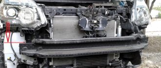
To change the air resonator, you need to unscrew the connection pipe and pull it out. Then, unscrew the two mounting bolts and remove the old device. Installing a new one is carried out in reverse order. Due to the wide variety of device shapes, it is possible to mount the resonator at several points, and to gain access sometimes you need to disassemble most of the front part of the car.
That's all you need to know about such resonators.
Air carbon filter
Carbon filters for purifying air from odors and harmful compounds are indispensable in everyday life and in small industries. The operating principle is as follows: the air flow that needs cleaning initially passes through a pre-filter that removes dust particles. This makes it possible to prolong the use of coal. Next, the air mass passes through the cylinders or filter cartridges, which contain the carbon layer. It comes out purified from 99% of impurities and chemical compounds. The effectiveness of such filters depends on the area of the room being treated.
The most popular models of household air purifiers are compact and carbon cassette filters. The first are U-shaped plastic frames with a carbon layer inside. Charcoal cassette filter - a stainless steel frame into which a carbon cartridge is inserted.
Design features
These devices have different shapes. They mainly differ in geometry, but there may be differences in the number of partitions located inside the element. There are main types of resonators:
- Monoblock. They consist of one container with a certain number of partitions necessary to separate two counter flows and reduce sound.
- Combined. Consist of two containers. The first serves to reduce high sound frequencies, the second - low ones. According to the distribution of sound reduction, the pulsations of air flows are leveled.
Regardless of the design features of the resonators, their main purpose is to ensure normal operation of the motor. Therefore, if the device breaks down, replace it. Otherwise, after a few kilometers you will notice disturbances in the operation of the engine. Replacing the resonator is not difficult; it can be done independently without the involvement of specialists.
Many car enthusiasts recommend removing this device. In their opinion, such actions will allow:
- Reducing the air intake point will improve engine power, and more oxygen will flow into the engine.
- The sound of a running engine will become similar to the sound of a powerful American car.
- Increased car acceleration dynamics - the additional resistance created by the resonator will be removed.
Please note: by removing this element of the system, you can cause partial oxygen starvation of the engine - this will lead to a major overhaul of the power unit, plus you will provoke a water hammer; if you drive into a deep puddle, water will get inside the engine.
Air filter - theory and practice
This work was submitted to our “unlimited” article competition. For a series of articles on air filtration, the author received a prize -
under Socket A.
Let's consider the processes occurring inside the system unit not only from the point of view of its cooling, but also the possibility of organizing air flow filtration. Let us take for consideration the conventional air flow diagram shown in Figure 1.
Conventionally, we assume that M1 is the mass of air entering through the front air intake.
M2 is the mass of air entering through various types of gaps. M3 – mass of heated air ejected from the system unit. According to the law of conservation of mass, the mass of all incoming air must be equal to the mass of all outgoing air of the system unit. The law can be interpreted as follows: A substance cannot disappear without a trace and come from nowhere.
Let us introduce for consideration an equation of the form M1+ M2= M3
Why are masses considered and not volume? The temperature of the incoming air is lower than that of the outgoing air, which means it has a higher density. The density of a substance determines its mass. This means that the mass of the same volume of cold and hot air will be different.
What needs to be done to prevent dust from appearing in the system unit? The answer is quite obvious: it is necessary that the air entering inside is clean. The simplest solution is to filter the air entering the system unit. The filter can be installed both outside and inside the system unit. Next, we will consider the option of installing the filter internally, although external implementations also have a right to exist. Let's put the filter on the main air flow M1. To keep the housing dust-free, all air entering the housing must pass only through the filter, and the M2 value (air through the gaps) must be zero or negative. Those. air should not enter, but exit through cracks and leaks in the system unit.
announcements and advertising
The cheapest 2070, there were no lower prices
Top Radeon Instinct 16Gb HBM2 on sale
Fierce mother S1200 ASUS ROG for 72 rubles.
New 4/8-core 3.6 GHz Comet Lake - 10 t.r.
6K 6016×3384 IPS
monitor on sale, see price
The newest LGA 1200 Asrock for 5 rubles.
The equation, in this case, must be transformed from the form M1+(-M2)= M3 to M1= M2+ M3. The circuit will be transformed to the form shown in Figure 2. If the condition M2 >= 0 is met, it is obvious that dust will not accumulate in the housing, because All air entering the housing will pass through the filter.
Let's consider options for organizing filters inside the housing. The simplest option is shown in Figure 3. In this case, the filter material is located after the fan.
This option has its advantages and disadvantages:
- + simplicity of design
- - fan contamination - to clean the filter, disassembling the housing is necessary.
Figure 4 shows the second option, when the fan is located after the filter. This is the best option from a common sense point of view. It is worth noting that most household vacuum cleaners work almost according to the same scheme, when dirty air first passes through a filter so as not to contaminate the fan and its motor.
Advantages and disadvantages of this option:
- + the fan does not get dirty
- + cooling of expansion cards by directed air flow
- - higher manufacturing complexity (a housing for the filter itself is required)
- - smaller filtration area, with the same filter volume, hence two more disadvantages: - needs more frequent cleaning
- — you need a more powerful fan or even two => higher noise level.
The most common filter at the moment is the option in the form of a flat gasket in front of the fan. This filter allows you to keep both the fan itself and the inside of the system unit relatively clean.
Along with the simplicity of the design and ease of cleaning the filter, it has disadvantages. Due to the small area of such filters (80×80=6400mm2), in order to create significant air flow, manufacturers have to reduce their flow resistance by increasing the size of its cells. The cleaning frequency of such a filter is higher than if there was a larger area filter.
Let's consider the issue of matching the fan and filter from a theoretical point of view. The operation of any fan can be represented by a graph called Fan Performance Curves. The characteristic is a curve showing the relationship between the performance of the fan and the pressure it creates. Below is the characteristic for 3 fans of the EC-8025xxxx brand (Low, Middle, High) manufactured by Evercool.
You can learn more about fans and their operation in the articles “Selecting case fans” and “Educational program on cooling systems. Lesson two."
For the convenience of considering the operating characteristics of the fan and filter, we present them in the form of straight lines. The actual filter characteristic has a nonlinear form. Graph 1 clearly shows that when the fan operates without load (idle P=0), it will produce its maximum performance M=max. If the fan is completely closed, then, obviously, its performance will be zero (M=0), while it will create its maximum air pressure (P=max). The filter characteristic shows that as the air flow pressure increases, the amount of air passing through the filter will increase.
What changes if you connect a filter to the fan? The filter material provides additional resistance to the flow, so we get some operating point 1 in our Graph 1. When the filter is dirty, the resistance to the air flow will increase, which means the performance (air quantity) will decrease. We find that our operating point during operation will steadily move towards a decrease in air flow and an increase in the pressure created by the fan. With a completely clogged filter, we get zero performance with maximum pressure.
The correct selection of fan and filter is carried out to ensure the specified performance indicators over a certain period of time. Those. A drop in performance from M11 to M12 is acceptable if the amount of air M12 is sufficient to ventilate the housing and the condition M1= M2+ M3 for Figure 2 is met. The time taken to move from point 1 to point 2 will determine the frequency of filter cleaning. The value of the M12 flow is conditional and can be determined indirectly by the deterioration of the cooling performance of the components of the system unit, as well as by the beginning of the appearance of dust (suction through cracks).
What should I do if the amount of air flow M1 at the very beginning is not sufficient to fully ventilate the case? There may be several ways to solve the problem:
Option 1: Reducing the filter resistance. This can be achieved by increasing the filter area or changing its material (see Graph 1).
2nd Option: Installing additional filters or fans. There are two sub-options to consider here:
- 1st - installation of another independent filter. At the same time, the total flow increases, as does the space occupied by the filters.
- 2nd - installing an additional fan on an existing filter.
How to install, serial or parallel? When installed in series, we will increase the pressure they create, which is what we need to overcome the filter resistance. If we take the filter resistance constant, then the introduction of the second fan can be displayed in Graph 2 with a new curve and a transition of the operating point from position 1 to position 2.
By installing two fans in parallel, we increase their total performance. Graph 3 shows a new characteristic for a filter with two parallel fans. Comparing Graphs 2 and 3, we can conclude that sequential switching on of fans, in the presence of resistance, gives a greater increase in filter performance.
3rd Option: Installing a more efficient fan.
Higher performance can be achieved both by higher impeller speeds and by choosing a fan with an impeller whose blades have a larger angle of attack. In addition, you can turn your attention to larger fans, for example 120 mm. Comparing the characteristics of 80 mm 120 mm fans, we can draw an interesting conclusion that the pressure created by 120 mm fans is almost the same as that of 80 mm fans, and their main the difference is performance. Centrifugal fans can be found to create higher pressure.
For the convenience of further work with the characteristics, we will transfer them to one chart. According to Graph 4, we can conclude that with comparable parameters (size, noise, power) of the 8025M and SB-E(M) fans, the latter can create a flow with higher pressure, while having a lower maximum performance.
The filter material has many characteristics, one of which is air permeability. On this site, the air permeability of various filter materials is indicated at a pressure difference of 50 Pa in units of dm3/m2s. This value shows how much air will pass through one square meter of material in one second at a pressure difference of 50 Pa. Depending on the type of material, it can vary over a wide range.
Let's make the necessary calculations to determine the filter's performance for different values of the material area, and therefore the filter sizes. Let us take for calculation a material with an average air permeability of 300 dm3/m2s. Let's convert 50Pa to millimeters of water column (mmH2O) using utilities (Uconner or Convert). In mmH2O the value will be 5.09. Let's convert dm3/m2s to CFM/m2 (cubic inches per minute per square meter). There are 30.48 centimeters in one foot. This means that one cubic foot contains 30.483 = 28316.85 cubic centimeters, or 28.32 cubic decimeters (10 cm = 1 decimeter). There are 60 seconds in one minute. We obtain a formula for converting values X=Y/28.32*60=2.12*Y, where Y is the value in dm3/m2s, and X is in CFM/m2. We find that 300 dm3/m2s is 635.59 CFM/m2.
Let's take two types of filters for consideration. The first is in the form of a square piece of material, and the second is in the form of a bag, shown in Figure 5.
The square filter area will be 80*80=6400mm2, which is 0.0064m2. The area of the bag depends on its shape. Let's consider the ideal option when the bag is a cylinder with a circle-shaped bottom. The total area of such a bag can be calculated using the formula Sbag=3.1416*D*L+(3.1416*D2)/4. Taking into account that the diameter of the bag taken as an example is 80mm (0.08m), the formula will take the form Sbag=3.1416*0.08*L+(3.1416*0.082)/4)=0.2513*L+0, 0050(m). Let's calculate the area of several filters for L = 10, 20 and 30 centimeters and enter the data in Table 1. For each value of the filter areas, we calculate the air flow they pass through, knowing that one square meter of our material at a pressure difference of 5.09 mmH2O passes 635 per minute .59 cubic feet of air. Table 1.
| Filter | Flat | In the form of a bag | ||
| Dimensions | 80x80mm | L=10cm | L=20cm | L=30cm |
| Area, m2 | 0.0064 | 0.030 | 0.055 | 0.080 |
| Airflow, CFM | 4.067 | 19.068 | 34.957 | 50.847 |
As already mentioned, the breathability of the material is specified for a pressure of 5.09 mmH2O. Let us plot the obtained data for several filters on Graph 5. We will construct the air permeability curves of the filters in the form of straight lines, assuming that to a first approximation they have a linear form.
Conclusions that can be drawn from this graph: firstly, it is quite obvious that having material and fans, you can assemble a filter that will provide the case with a certain amount of air.
For example, a filter made from the selected material with a 20cm bag size and an 8025M fan will produce 10 CFM (cubic feet per minute). Secondly, the size of the filter affects the resistance it will provide to air flow. If you make a filter from the selected material in the form of a square measuring 80x80, then the throughput with the same fan will be approximately 2 CFM, which, of course, will not be enough to fully ventilate the case. It follows that when using the same fans to increase performance, it makes sense to maximize the filter area, thereby increasing the frequency of its cleaning. Thirdly, it makes sense to use centrifugal fans only with high resistance filters, otherwise the performance of such a filter will be less than using a conventional fan. Above we discussed the operation of filters without taking into account the resistance created by the housing.
Obviously, the filter will be most effective when the housing resistance is minimal. To ensure this condition, it makes sense to design various types of blowholes and install blow-out fans, not forgetting that the efficiency of such a circuit is achieved only if all the air entering the system unit passes through the filters. Let's move from theory to practice. The first version of computer modification was undertaken on my first computer based on Intel Pentium 233. Now it works as a server for a small local network.
The circuit shown in Figure 3 was chosen. Several combinations of materials and fans (up to 220 volt) were tried. Ultimately, the most effective option turned out to be the option with two regular 80 mm. fans and a lavsan bag of impressive size. As it was found out later, the performance of one 80 mm fan is quite enough to blow through a bag with half the area.
In the front wall of the computer, including the panel, two holes were cut coaxially for an 80 mm fan. A 20 mm thick ring with outer and inner diameters of 78 and 111 mm, respectively, was cut out of a piece of chipboard. Both fans were attached to the front wall of the computer through a ring using threaded rods, onto which nuts were screwed on both sides.
The canvas bag was fixed to the ring using a car clamp. The power supply fan was turned on through a resistance so that its performance was less than that of the filter. Because This option implied active contamination of the filter fans; their plain bearings were replaced with rolling bearings to increase the service life of the fans.
For the last two years, the computer has been running almost without shutdown. If you take a closer photo of the insides, you won’t see any dust there, even on the processor fan. Believe it or not, he didn't vacuum before taking the photo.
As you can see, the filter material has acquired a gray color, this is especially visible in comparison with the new filter.
In 4 years of use, the bag was shaken out only twice. The first time was about a year or a year and a half ago, and the last time was after receiving these photos. The photo below shows the contents of the bag. There is a lot of dust, but there is still room for it.
If you turn the bag inside out, you can even find some living creatures there. Here's another advantage of such a system 
With the advent of a computer based on the Athlon 900, it became possible to continue experiments. This time the diagram in Figure 4 was taken as a basis. A distinctive feature of this option was the installation of a fan after the filter material. After some experimentation with the AutoCAD program, a 3-dimensional graphical model of the filter was obtained.
As planned, air with dust was supposed to be sucked into the filter from the outside, and then thrown out by fans inside the case. Unlike the model, it was decided to make the filter material in the form of a 3-fold nested cone to increase the area. A cross-section of such a filter is shown below.
In order for the air flow passing through the filter to be good, it was necessary to install 2 fans on each cone. To reduce the noise created by the mutual influence of the two fans, they were separated by a ring cut from chipboard. In the real implementation, it was decided to install two such filters. A flow was created in the upper part of the case to cool 5.25″ devices. At the bottom there was a directed flow for expansion cards. The filter housings were made from flower pots, which were pulled to the housing with brackets, thereby clamping the filter material.
This implementation option had two significant drawbacks:
- The cones amplified the noise of the fans, similar to how a horn works. The system was quite effective, but very noisy.
- The process of removing and installing filters was extremely inconvenient.
I am inclined to conclude that these were not shortcomings of the proposed scheme, but rather the results of an unsuccessful version of its implementation. As a result, I returned to the option shown in Figure 3 and described in the article “Mod of my computer - air filter.”
In this option, air enters the case in almost the same way, with the only difference being that it goes through the fans first. The air from the case is exhausted from the power supply, mobile racks and a homemade air vent on the processor. Among the advantages of this scheme, it is worth noting its simplicity and ease of access to filters. Among the disadvantages: the warm air coming out through the rear wall is partially sucked back into the upper rear filter. In the lower part there is no directed flow towards expansion cards, including the video card. A more sophisticated system was made for my friend’s body, because... there was not much space. The process of manufacturing the system is described in the article “Mod for a friend on the topic of air filtration.”
The effectiveness of all the filters described above was determined very simply. After some time of operation, the system unit was opened and it was inspected for dust. Even a small amount of it was enough to conclude that the circuit was not working as it should. After this, the necessary changes were made to the system and the process of determining the effectiveness of the work was repeated. At the same time, due attention was paid to the thermal conditions of the system unit, because no one needs a computer that is even sterile, but burnt out or glitches.
With these words I end my trilogy of articles on filtration. I hope these articles will be useful to novice experimenters in this field.
Best regards, DustKiller
We look forward to your comments in a specially created conference thread.
Checking the resonator
Communities Lada Priora Lada Priora Club Blog Micro FAQ 2. Checking the functionality of the expansion tank cap
When identifying the problems listed above, every motorist should know how to check the resonator. This will not only normalize the operation of the engine and exhaust system, but also increase the comfort of using the car, including for the people around you.
To check, you will need an inspection hole (if you don’t have one, you can jack up the car). Diagnosis is made using visual inspection. During the process, it is necessary to carefully examine the integrity of both the device itself and the pipes connected to it (especially at their joints).
A clear sign of a problem is the formation of condensation in the cooling resonator, after which it begins to drip to the ground. This means that its body has lost its tightness and must be repaired, or better yet, replaced. You can check for condensation after a while, when you turn off the engine (to allow the resonator body to cool)
Note! Some car enthusiasts, when making resonators on their own, specially drill a hole in its body to remove moisture. Therefore, if you bought a car with a similar resonator, then this testing method will not work for you
Also, the integrity of the resonator body can be determined by the presence of exhaust gases leaving it. This also indicates depressurization and the need to replace it. This fact can be checked with the car engine running by looking under the bottom. To be sure, you can ask an assistant to “turn on the gas” at the same time so that more exhaust gases pass through the system. Also, suspicion of depressurization is caused by the appearance of smoke from under the bottom of the car while driving or when parked with the engine running.
Functions of the resonator and the need for its presence
Priora resonator
The resonator is an integral part of the exhaust system. It is responsible for the time-accurate removal of already exhaust gases from the chamber of the power unit, respectively, freeing the chamber for new ones.
Most professionals believe that the quality of the resonator alone determines the useful and obtainable power of the engine. It is for this reason that sports cars with high power characteristics are modernized in terms of replacing standard (standard) resonators with more advanced options.
The resonator is located behind the forward flow, which ensures its ability to accept the bulk of toxic and high-temperature gases. It is easy to understand that the high-quality operation of the resonator directly affects the improvement of the driving properties of the car.
Resonator device
Communities VAZ Repair and Modification Blog Cleaning the throttle valve of the VAZ 2115. Faulty lambda probe oxygen sensor
Structurally, the resonator consists of a perforated (drilled along the entire length within the device) pipe placed in a metal casing. The design also has a throttle hole designed to increase the efficiency of damping wave vibrations in the pipe. The internal cavity of the resonator is divided into two or more unequal parts by partitions located in a transverse plane to the pipe. Also, more modern exhaust resonators are designed with thermal insulation and/or sound insulation (often the same material) located under the housing and designed to reduce its temperature and/or sounds emanating from the device.
Internal structure of the resonator
The internal cavities have an unequal volume in order to ensure periodic narrowing and expansion of the flow of exhaust gases, which in turn equalizes their uneven pulsation. That is, each chamber has its own resonant frequency. In addition, they have a slight offset relative to the axis of the body. This is necessary to achieve a change in the direction of the exhaust flow. And internal perforation on the pipe is needed to dampen the large amplitude of sound waves that produce gases.
The efficiency of the resonator is influenced by the following factors:
- the degree of its wear, tightness;
- level of contamination from soot (the cleaner, the more effective);
- diameter (the larger the diameter of the device, the greater its efficiency).
How to choose the right carbon filter?
When purchasing a carbon odor purification filter, pay attention to its quality; to do this, you need to make sure that the seller has certificates confirming the quality. Its performance should correspond to that of the fan, or better yet, even exceed it. Because if you have a performance reserve, you will extend the service life of your filter by at least 1.5, or even 2 times. For example, if the volume of your ventilation channel is 250 m3, and you install a 500 m3 filter on it, you will thereby increase its service life by 2 times.