Content
- 1 Supercharger as an element of aggregate supercharging 1.1 Application of the supercharger and its functions
- 1.2 Absence of a supercharger as part of the gas turbine engine
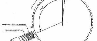
- 1.3 Types of superchargers according to their energy drive
- 1.4 Meaning of the terms “supercharger” and “compressor”
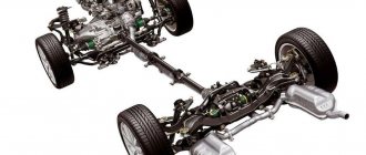
- 3.1 Specifics of application on automobile engines
Supercharger as an element of aggregate supercharging
Application of a supercharger and its functions
Supercharger operation on two-stroke and four-stroke engines
The supercharger can be used on piston and rotary-piston internal combustion engines operating in any thermodynamic cycle and with any number of strokes. For most types of such internal combustion engines, the supercharger is an optional design element that does not affect the fundamental ability of the internal combustion engine itself to operate. The main task of the supercharger here is to boost the engine in order to increase power. By supercharging we mean, first of all, the forced injection of air into the internal combustion engine with a pressure above the current atmospheric level, leading to an increase in the density and mass of air in the combustion chamber before the power stroke, which, in turn, according to the rule of the stoichiometric combustible mixture for a specific type of engine, allows burn more fuel, which means more torque (and power, respectively) at any crankshaft/rotor speed comparable to a naturally aspirated engine. Within the framework of this task, supercharging using a supercharger is only one of the possible methods of boosting and/or increasing efficiency, and the presence or absence of a supercharger is determined only by the goals and budget of the developers of a particular engine. The only exception to this rule is some types of two-stroke piston internal combustion engines, where the supercharger primarily performs the task of forced purging of the cylinders at the junction of two power strokes and is almost always present in the intake system of such an internal combustion engine.
Absence of a supercharger as part of the gas turbine engine
In gas turbine internal combustion engines, a supercharger is formally absent. The compressor, which is part of any gas turbine internal combustion engine, is an absolutely integral element of the design, ensuring the fundamental possibility of operation of such an internal combustion engine, and such a compressor is not called a supercharger in the Russian engineering lexicon, although it performs the function of forced air injection.
Types of superchargers according to their energy drive
The supercharger works due to one or another type of energy received from the internal combustion engine itself, either directly or indirectly. It is possible to use the energy of exhaust gases, mechanical energy of rotation of internal combustion engine shafts, and electrical energy. Depending on its energy drive, the supercharger design has its own technical features and its own name. Superchargers powered by exhaust gas energy are called turbochargers, while those powered by a mechanical drive are called drive superchargers. There are also superchargers that operate on electrical energy, but there is no established Russian-language term to describe them yet and they can be called both electric superchargers and electric-driven superchargers.
The meaning of the terms “supercharger” and “compressor”
An important element of the supercharger is the air compressor, which is present in the design of absolutely any supercharger, regardless of its energy drive. In this context of aggregate supercharging, both terms - supercharger and compressor - are used equally, including as part of compound words such as turbocharger/turbocharger, which for those uninitiated in the topic may raise questions about the semantic shades of the terms. It should be understood that, from a semantic point of view, the term “supercharger” implies the function of the entire unit as a whole, and “compressor” is the name of the energy machine and the main executive unit of absolutely any supercharger. In Russian-speaking speech, the equal use of both terms in relation to supercharging is actually permissible, and both words, both in simple and complex form, in this case can be considered synonyms.
In the theory of vane machines, the terms “supercharger” and “compressor” are not identical. Typically, blade machines that increase the flow pressure by no more than 10% are classified as fans; by 20...25% - to superchargers; higher pressures correspond to compressors. In common parlance, a supercharger assembly is often called a “turbine,” although in a drive supercharger there is no turbine at all, and in a gas turbine it is only the drive of the supercharger/compressor.
Types of supercharging of internal combustion engines
< Back
Next >
The task of increasing engine power and torque has always been relevant. The simplest solution is to increase the displacement: the more fuel burned, the higher the power. However, this significantly increases the dimensions and weight of the structure.
An alternative approach is to leave the engine displacement the same, but supply more fuel per unit time. It is not difficult to increase the gasoline supply, especially in injection systems. But at the same time, in order to maintain the composition of the fuel mixture, it is necessary to proportionally increase the amount of air supplied to the engine. The engine’s ability to independently suck in air is limited, so you cannot do without a special device that increases the pressure and, therefore, the amount of air at the intake. These devices are usually called blowers or compressors.
Mechanical supercharger
Mechanical superchargers were used in automobile engines back in the 1930s, when they were most often called compressors. Nowadays this term usually refers to turbochargers, which will be discussed below. There are quite a few designs of mechanical superchargers, and developers are still showing interest in them. Figures 1-4 show diagrams of some devices, the operating principle of which does not require additional explanation.
There are designs that are not quite ordinary. One of them, the Comprex wave supercharger (Fig. 5), belongs to the Asea-Brown-Boweri company. The rotor of this compressor has axially located chambers, or cells. As the rotor rotates, fresh air enters the cell, after which it approaches an opening in the housing through which hot engine exhaust gases enter it. When they interact with cold air, a pressure wave is formed, the front of which, moving at the speed of sound, displaces air into the opening of the inlet pipeline, to which the cell manages to approach during this time. Since the rotor continues to rotate, the exhaust gases do not have time to enter this hole, but exit into the next one along the rotor’s path. In this case, a vacuum wave is formed in the cell, which sucks in the next portion of fresh air, etc.
The Comprex supercharger has already been tested by several car manufacturers, and Mazda has been using it on one of its production engines since 1987.
Another unusual design is a spiral or G-shaped (shaped like the letter G, reminiscent of a spiral) supercharger. The idea was patented at the beginning of the century, but due to technical and production problems, no one dared to produce such a supercharger for a long time. The first, in 1985, was Volkswagen, which used it on the Polo coupe engine (1.3 l, 113 hp). In 1988, a more powerful G60 supercharger appeared, which for several years was equipped with Corrado and Passat engines (1.8 l, 160 hp), and the Polo G40 was produced until 1994.
Schematically (Fig. 6), the design of a G-shaped supercharger can be represented in the form of two spirals, one of which is stationary and is part of the housing. The second - the displacer - is located between the turns of the first and is fixed on the shaft with an eccentricity of several millimeters. The shaft is driven from the engine by a belt drive with a ratio of about 1:2.
When the shaft rotates, the internal spiral makes oscillatory movements and crescent-shaped cavities are formed between the stationary (housing) and the running (displacer) spirals, which move towards the center, moving air from the periphery and supplying it to the engine under slight pressure. The amount of air moved depends on the engine speed.
The system has a relatively high (about 65%) efficiency. There are almost no rubbing parts, so the wear of parts is insignificant. The G40 supercharger installed on the Polo engine (40 and 60 in Volkswagen supercharger markings is the width of the volute chambers in millimeters) has an internal compression ratio of 1.0; The maximum boost pressure is 0.72 bar. At a nominal rotor speed of 10200 rpm. 566 cm3 is supplied per revolution. air, i.e. almost 6000 l/min.
The control circuit for a mechanical supercharger is quite simple (Fig. 7). At full load, the wastegate valve is closed and the throttle valve is open - all air flow enters the engine. When operating at partial load, the throttle valve closes and the pipeline damper opens - excess air is returned to the supercharger inlet.
The charge air cooler (Intercooler) included in the circuit is an almost indispensable component of all, not only mechanical, charging systems. When compressed, air, as is known, heats up, and its density and, accordingly, the amount of oxygen per unit volume decreases. More oxygen means better combustion and more power. Therefore, before being supplied to the engine, the air compressed by the supercharger passes through the cooler, where its temperature is reduced.
The advantages of a scroll supercharger, like most mechanically driven compressors: sufficiently high torque and increased engine power at low speeds, fast, almost instantaneous response to pressing the gas pedal. Disadvantages: relative complexity and low-tech design, large losses in the drive.
Turbocharger
Turbochargers are more widely used in modern automobile engines. They are more technologically advanced to manufacture, which compensates for a number of their inherent disadvantages.
A turbocharger differs from the designs described above primarily in its drive circuit (Fig. 8). It uses a rotor with blades - a turbine, which is rotated by the flow of engine exhaust gases. The turbine, in turn, rotates a compressor located on the same shaft, made in the form of a wheel with blades.
The selected drive scheme (gas instead of mechanical) determines the main disadvantages of the turbocharger. At low engine speeds, the amount of exhaust gases is small, and accordingly, the compressor efficiency is low. In addition, a turbocharged engine, as a rule, has a so-called "turbo lag" - a slow response to an increase in fuel supply. You need to accelerate sharply - you press the gas pedal to the floor, and the engine thinks for a while and only then picks up. The explanation is simple - it takes time to spin up the turbine, which rotates the compressor. In Fig. Figure 9 shows the response of various types of superchargers to an increase in engine speed. The curves shown apply to a diesel engine, but their character remains the same for a gasoline engine. It is clearly seen that the turbocharger has the slowest response, the wave supercharger reacts faster, and the mechanical supercharger operates almost instantly.
Designers are trying to get rid of these shortcomings in different ways. First of all, by reducing the mass of rotating parts of the turbine and compressor. The rotor of a modern turbocharger is so small that it easily fits in the palm of your hand. The lightweight rotor increases the efficiency of the compressor at low engine speeds: for example, with the 2.0 l turbo engine of the SAAB 9000 already at 1500 rpm. the increase in torque due to supercharging is 20%. The lightweight rotor, in addition, has less inertia, which allows the turbocharger to spin up faster when the gas pedal is pressed and reduces “turbo lag”.
Weight reduction is achieved not only by the design of the rotor, but also by the choice of appropriate materials for it. Many companies are searching for new materials for turbines. The main difficulty is the high temperature of the exhaust gases. Perhaps the Japanese have succeeded most in this area - they have been working on ceramics for internal combustion engines for a long time. A monolithic turbine made of sintered silicon carbide, with the same mechanical strength, weighs 3 times less than a conventional one and, accordingly, has much lower inertia. In addition, in the event of a rotor rupture, the flying fragments will be much lighter - this makes it possible to make the compressor housing thinner and more compact. And recently, Nissan designers, for the first time in world practice, managed to create a supercharger impeller made of plastic. It’s unknown what it’s made from, but they say it turned out to be very light.
Getting rid of the shortcomings of a turbocharger allows you not only to reduce the inertia of the rotor, but also to use additional, sometimes quite complex boost pressure control circuits. The main tasks in this case are to reduce pressure at high engine speeds and increase it at low speeds. One task can be solved quite easily: excess boost pressure at high speeds is reduced, usually with the help of a wastegate.
The other task is more difficult. All problems could be completely solved by using a turbine with variable geometry, for example, with movable (rotating) blades, the parameters of which can be changed within a wide range. Such turbines are widely used in aviation and other fields of technology. But it is difficult to place the blade rotation mechanism in the tiny rotor of a car compressor.
One of the simplified methods is to use an exhaust gas flow rate regulator at the turbine inlet. The Garrett VAT 25 turbocharger, which will be discussed in more detail below, uses a movable damper for this.
The boost pressure control diagram for 2.0 and 2.3 liter SAAB 9000 engines is shown in Fig. 10. It's called APC - Automatic Performance Control. The APC system maintains boost pressure at the maximum permissible level in all engine operating modes, without causing the engine to detonate. For this purpose, a sensor (knock sensor) is used, according to a signal from which, when detonation occurs, the control unit opens the bypass valve installed in the turbine, and part of the exhaust gases is directed bypassing the turbine wheel, which reduces the boost pressure and eliminates detonation. In addition to this sensor, the APC system also includes others that measure engine speed, load, temperature and octane number of the fuel used - these parameters determine the detonation threshold.
The use of APC made it possible not only to increase the compression ratio of the 2.0 liter engine to 9, but also made it possible to use fuel with a low octane number - up to 91.
Fuel efficiency
Increasing engine power, whether achieved by increasing its displacement or using supercharging, inevitably entails an increase in fuel consumption.
Theoretically, the efficiency of supercharged engines is slightly higher than that of atmospheric engines, so their specific (per unit power) fuel consumption should be lower. In practice, due to losses during transient processes, it turns out to be approximately the same. Of course, you can drive relatively economically with a turbo engine, but then why is it needed? Therefore, today designers are trying to solve a difficult problem: reducing fuel consumption while maintaining high power. Let's try to consider different approaches to this problem, proposed, for example, by Audi and Peugeot engineers.
One of the ways to increase engine efficiency, as is known, is to increase the compression ratio. But supercharged engines have a limitation: supercharging increases compression, which leads to detonation, especially at high speeds. Therefore, the compression ratio has to be artificially reduced: in a modern naturally aspirated engine it is about 10, and in a supercharged engine it usually does not exceed 8.
Audi designers managed to overcome this limitation to a certain extent: in the 5-cylinder 20-valve engine of the Audi S2 and Audi S4 with a volume of 2.2 liters and a power of 230 hp. With. The compression ratio is increased to 9.3 - this is unusually high for a turbo engine. Result: average fuel consumption at 90 km/h is 7.5 l, in the city - 14 l/100 km. The engine came from the sports Audi 200. The Avant RS2 engine, created on the same basis, also has a fairly high compression ratio - 9, but with the same volume it develops a power of 315 hp. With. (by changing the boost parameters). At the same time, fuel consumption in the city is only 14.5 l/100 km.
The aforementioned 2.0-liter turbocharged 4-cylinder engine of the new SAAB 9000 also has a compression ratio of 9. Less power: 165 hp. s., but fuel consumption on the highway is less than 7, and in the city - about 12 l/100 km.
Compare these parameters, for example, with the data for the Porsche 968 Turbo S. A sports car, they did not pay much attention to fuel economy. Displacement 3 liters, 4 cylinders 2 valves/cylinder, compression ratio 8, power 305 hp. s., fuel consumption in the city is at least 18 l/100 km.
Since Audi designers took the path of increasing the compression ratio to increase efficiency, they were able to limit themselves to a turbocharger of a completely traditional design: K24 from KKK (Kuhle, Kopp und Kausch). The boost control scheme is also traditional - excess pressure at high speeds is limited by the bypass valve. The dimensions of the K24 are small, and the parameters were selected based on obtaining high torque at low speeds. Already at 1950 rpm. the engine reaches its maximum torque (350 Nm), which is maintained until 3000 rpm. The torque curve is quite flat: 90% of its value is located in the rotation speed range of 2300-5200 rpm. Despite the simplicity of the control circuit, “turbo lag” is not felt in this engine.
Peugeot designers took a different approach. The new 4-cylinder 16-valve engine of the Peugeot 405 T16 has a low compression ratio of 8, traditional for turbo engines. But it uses a rather tricky Garrett VAT 25 compressor (not to be confused with VAT 69 - this is from a completely different area!). In relation to a compressor, the abbreviation VAT is a turbine with a variable area, or cross-section (Variable Area Turbine). At the exhaust gas inlet into the turbine housing there is a movable damper with a pneumatic drive (Fig. 11). At low engine speeds, the damper is in the closed position, reducing the cross-section of the channel through which the flow of exhaust gases passes, so even with a small volume, the flow speed is quite high and provides the required turbine speed. As the engine speed increases, the damper opens, increasing the flow area - the amount of exhaust gases increases and, accordingly, the boost pressure increases. Since VAT is a simplified solution and does not fully provide regulation, the bypass valve had to be retained in the boost pressure control circuit.
Overall, it turned out quite well. The Peugeot engine reaches its maximum torque of 288 Nm at 2600 rpm, and this value is maintained until 4500 rpm. In this case, 90% of the torque value is located in the range of 2300-5200 rpm. With a volume of 2.0 liters, the engine develops a power of 200 hp. With. (5000 rpm), and fuel consumption in the city is less than 12 l/100 km.
Overboost
As a rule, turbocharged engines have an Overboost device, which is activated when the gas pedal is pressed sharply and further increases the boost pressure and maximum engine torque (by about 10%). This is necessary during sudden accelerations, for example when overtaking.
On an Audi with a K24 compressor, the activation of this mode is achieved, in general, traditionally: when the throttle valve is opened sharply and completely, the electronic control unit is activated, which quickly closes the boost pressure control valve. The entire flow of exhaust gases is directed through the turbine, the boost pressure is further increased - Overboost. In this mode, already at 2100 rpm. engine torque reaches 380 Nm.
Peugeot designers acted differently. For the Garrett VAT 25 compressor (Fig. 11), the Overboost effect is achieved due to the fact that the damper in the turbine housing quickly tilts in the direction of the turbine wheel, sharply increasing the flow area and, accordingly, the incoming amount of exhaust gases. The torque of the 405 T16 engine in this mode increases to 318 Nm at 2400 rpm.
The increased torque lasts for a limited time: Audi for 16 seconds, Peugeot for 45 seconds, which is almost ideal for overtaking. To avoid damaging the engine, the Overboost mode does not operate if the engine speed exceeds 6000 rpm. (Audi) or if 1st gear is engaged (Peugeot).
How much does supercharging cost?
As you know, only the wind in the reeds is free. Increasing the power of supercharged engines comes at a price. And not only by increasing fuel consumption. The requirements for its quality are increasing - most turbocharged engines require gasoline with an octane number of 96-98. Despite the fact that the pistons, rings, heads and connecting rods are strengthened, the engine life is noticeably reduced, the more so the higher the boost pressure. We can assume that on average the service life of an engine with a turbocharger does not exceed 100 thousand km, and the service life of the compressor itself is about 10 thousand hours. For mechanical superchargers it is higher - about 25 thousand hours. The turbocharger lubrication system requires special oils that can withstand high temperatures and rotation speeds of more than 100,000 rpm. The temperature in the turbine part of the compressor reaches up to 1000°C, so its bearings require additional water cooling. All of the above for the consumer results in a fairly significant increase in the cost of the car and its maintenance.
For gasoline engines of mass-produced models, supercharging can hardly be considered a successful way to increase power. Volkswagen, for example, abandoned the above-mentioned supercharged engine in the Polo this year. More promising, especially from the point of view of fuel efficiency, apparently, can be considered such areas as multi-valve technology, improvement of injection systems, leaner mixture and its layer-by-layer distribution in the cylinders.
Turbocharged gasoline engines are, perhaps, the preserve of expensive, sporty cars. Maserati, for example, can afford to produce all engines with a supercharging system, and even with not one, but two turbochargers - on V-twin engines. This design is called Twin Turbo. Easy to remember - like a Twin bed in a hotel. Sometimes the name is transformed into Biturbo, which does not change the essence of the matter: turbochargers stand in parallel and each serves its own section of cylinders.
As a rule, few people can buy such a car. True, with the current Russian tax policy, when you have to pay a duty on engine volume, some may prefer a turbocharged version, since they are still available in the catalogs of most manufacturers. A matter of taste. And money. By the way, Mercedes-Benz and BMW, whose products are so popular in our country, do not have a single serial gasoline turbo engine today.
From economic, environmental, and many other points of view, turbocharged diesel engines look very attractive.
Publication date: 2007-12-29
< Back
Next >
Turbocharger
Turbocharger assembly.
Turbine - on the left, compressor - on the right. A simple cross-section of a fixed-geometry turbocharger. This is a supercharger, the design of which includes a miniature turbine, and the operating principle is based on using the energy of the exhaust gas flow of the engine itself, which is being pressurized. Exhaust gases, acting on the turbine located in the exhaust system immediately behind the exhaust manifold, spin it, and it transfers rotational energy to the compressor. The fundamental design of each of the two actuator units of the turbocharger is generally identical for any development brought to the stage of an operating unit, and assumes one radial single-circuit turbine and one centrifugal compressor. At the same time, the actual design of the turbine, compressor, shaft and housing can be very different: for example, in addition to the canonical simple combined turbochargers of fixed geometry on plain bearings, it is possible to use turbines of variable geometry, the use of double spiral channels for supplying gases to the turbine (the so-called Twin-Scroll) , the use of double air outlet channels from the compressor, the separation of the turbine and compressor at a significant distance from each other, the use of ceramic rotors, the installation of the shaft on rolling bearings. Important (although not particularly declared) criteria for the power and efficiency of a turbocharger are the outer diameters of its turbine and pump wheels (which can be approximately assessed visually by the size of the housing), the rotor speed and the amount of turbo lag inherent in all turbines without exception.
The turbocharger always operates at high exhaust gas temperatures, and the turbocharger shaft bearings are the most thermally stressed engine part that comes into contact with the engine oil, which imposes special requirements both on the production technology of the parts that make up the turbocharger, and on the quality of the oil and its service life. Both have long been one of the limiting technological factors for any mass introduction of turbochargers on gasoline engines.
Any gasoline engine with a turbocharger is initially designed for supercharging. The use of a turbocharger on a gasoline engine, originally designed as naturally aspirated, without modifications is in principle possible, but will lead to rapid (if not instantaneous) destruction of such an engine during operation. The need for constant control of detonation requires the presence of some kind of control electronics, which usually means a motor power system based on electronic (or at least electronic-mechanical) injection. Mass-produced carburetor engines with turbochargers were extremely rare due to the excessive mechanical complexity of their power systems. Turbochargers are widely used on diesel engines of commercial vehicles - on the engines of trucks, tractors, locomotives, and ships. Here, the enabling factors were the increased knock resistance of diesel engines and their higher efficiency, which implies a lower level of thermal radiation, the relative undemandingness of the efficiency of a commercial vehicle engine in transient conditions, and sufficient space in the engine compartment.
A feature of the operation of a turbocharger in comparison with other supercharging units is that when it is used, the effect of supercharging always exceeds the energy costs of supercharging. That is, for any engine equipped with a turbocharger, it is always possible to obtain a boost mode that forces the engine so much that it destroys it. The power of any engine with a turbocharger is 100% limited by the strength of the engine itself, its service life, and not by the efficiency of the turbocharger. The need to limit the effect of supercharging is the reason that a turbocharger is never used on engines by itself, but only in an integrated manner as part of a turbocharging system, in which it is its main element, but not the only one.
Centrifugal supercharger sound
Since the volutes of centrifugal superchargers must be much larger in size compared to turbocharging, in order to obtain the same air pressure at the inlet, due to the much lower speeds of their use, the sound they produce is audible even at low engine speeds. And even at idle, when the small turbocharger impeller may practically not rotate, the large centrifugal supercharger impeller rotates at 7000-10000 rpm, creating very loud and at the same time, pleasant “maybe not everyone” sounds.
Driven supercharger
Volumetric drive supercharger Roots Volumetric drive supercharger PowerPlus based on a vane vane pump
This is a supercharger, the design of which consists of a compressor and some kind of mechanical drive, through which, in turn, the operation of the supercharger is ensured by using the power received from the motor to which the boost The drive supercharger does not have a single general appearance. Based on the principles of operation of their compressor, drive superchargers can be volumetric, that is, they charge pulses in portions of a certain fixed volume, and dynamic, that is, they charge in a continuous flow. The group of volumetric superchargers includes such designs as: cam (American Roots
,
Eaton
), screw (American
Lisholm
, German
Mercedes
of the 2000s), spiral (German
G-Lader
, used on Volkswagen of the 1990s), vane (British
PowerPlus
for pre-war and Rolls-Royce Merlin). Dynamic drive superchargers are known only of the centrifugal type; they usually do not have known proper names, and their design is more or less universal and, in general, is similar to the design of a certain canonical centrifugal compressor. In both cases, regardless of the type of compressor, the design of its mechanical drive is not of fundamental importance for the operation of the supercharger as a whole, with the only peculiarities that the compressor drive has an increasing gear ratio (about 0.15-0.08), and other drive designs allow you to turn on/off the supercharger (including using the analogue principle) at the command of the driver or control unit. The drives themselves are possible by intermediate shafts, gears, toothed belts, chains, a set of trapezoidal belts, as well as direct drives from the ends of the crankshaft or camshaft. In cases of disconnectable drive, couplings of various designs are used.
A peculiarity of the operation of a drive supercharger in comparison with other supercharging units is that the motor is forced to expend a significant part of its so-called indicator power to drive it. This leads to the fact that all engines with drive superchargers have a high specific fuel consumption, which can be several times higher than the specific fuel consumption of a naturally aspirated engine of comparable net power. At high engine speeds, the power consumption for driving the supercharger grows non-linearly relative to the increase in output from its use, which further increases the specific fuel consumption values, and the difference between the indicated power and the net power at maximum modes can reach a value of 50% of the net.
Due to the relatively low level of thermal stress during operation, drive superchargers are relatively undemanding in terms of metal technology and lubricant quality, and an efficient, reliable supercharging unit based on a drive supercharger was available for production almost simultaneously with the advent of mass-produced cars. However, due to the requirements for precision in the production of parts, drive superchargers were in any case expensive, and their use in the first half of the 20th century was limited to exclusive, pseudo-sports or racing cars. The second area of application for drive superchargers was piston aircraft engines, in which the boost was designed to compensate for the decrease in atmospheric pressure at altitude and the associated rarefaction of air. After WW2, aviation switched to turbojet engines, and car engine designers followed the path of naturally aspirated boosting, as a result of which drive superchargers were almost forgotten, and only American tuning or some American and rare European models of road cars remained their lot. In the early 2000s, drive superchargers began to appear on relatively expensive road cars as part of combined supercharging units paired with a turbocharger. Such supercharging systems are still in use today, although in recent years there has been a tendency to replace combined supercharging with efficient all-mode turbocharging based on Twin-Scroll turbines or variable geometry turbines, as well as combined supercharging with a turbocharger and an electric supercharger.
Specific application on automobile engines
Roots positive displacement supercharger in operation
On gasoline engines of serial passenger cars, in cases where a supercharged engine is developed based on a drive supercharger, such a supercharger will always be only of the positive displacement type. The rationale for this is the important quality of any volumetric compressors that their performance always has a linear dependence on the rotor speed. That is why engines with positive displacement superchargers are convenient for the driver: they work in transient modes no worse than naturally aspirated ones (they do not have any delay in the engine spin-up when you press the gas pedal) and increase torque throughout the entire speed range, which is the case with an engine with a positive displacement supercharger especially noticeable at the “lower” levels. Also, positive displacement superchargers have the design advantage that their use does not require any additional control elements and systems (pressure relief valves, electronic control units, additional sensors), which, during periods of absence of electronic injection systems, made it possible to easily install positive displacement superchargers on carburetor engines. motors or motors with mechanical injection. In modern combined supercharging systems, in the case of using volumetric drive superchargers, they are responsible for supercharging at low engine speeds and are taken out of operation by control systems when sufficient boost pressure is achieved by the parallel operating turbocharger.
ATI ProCharger Centrifugal Driven Supercharger
Centrifugal superchargers can also be used on gasoline engines of passenger cars. But due to the fact that in any centrifugal compressors the dependence of the volume of pumped air on the speed is not linear, drive superchargers based on them are either connected for a short time (like American tuning machines) or installed on motors for which the efficiency of operation in transient modes and efficiency Low-end work is not very important (for example, quarter-mile racing cars). At the same time, installing a plug-in drive centrifugal supercharger on an initially naturally aspirated engine may not require modifications for boosting if the engine operating time in boost mode is limited. And the installation of a constantly operating centrifugal supercharger, in addition to modifications for supercharging, may require the presence of pressure relief valves (which is not necessary in the case of positive displacement superchargers). In any case, conventional production road cars are not equipped with centrifugal superchargers.
Both positive displacement and centrifugal drive superchargers can be used not only on gasoline engines of passenger cars, but also on gasoline and diesel engines of heavy equipment. The choice of a drive supercharger rather than a more suitable turbocharger here is likely due to the specific application. An example of the first case is the American Teledyne Continental AVSI-1790 tank gasoline engine; An example of the second is the Soviet/Russian tank diesel engine B-46.
In modern mass automotive engine production, the use of drive superchargers is disappearing. The main reason for this is mechanical losses in the drive, resulting in increased fuel consumption and increased carbon dioxide emissions. An adequate replacement for volumetric drive superchargers today are turbochargers with Twin-Scroll turbines and variable geometry turbines, as well as the use of electric-driven superchargers in combined supercharging systems, which in all cases somehow helps solve the problem of turbo lag in transient modes and the problem of low efficiency of conventional turbocharging at low engine speeds.
Specifics of application on two-stroke engines
Centrifugal blower (2) on a two-stroke engine with counter-movement of pistons. Positive displacement blower on a two-stroke motor with valve-slot purge.
On certain types of gasoline and diesel two-stroke engines (with valve-slot purge, with counter-movement of pistons), the operation of which requires relatively low speeds. Low-pressure drive superchargers are used as an integral element of the entire structure for purging the cylinders at the junction of two power strokes. In the Soviet engineering lexicon, such drive superchargers were called " blower"
" or "
purge pump
". The boost pressure they provide is usually on the order of 0.1-0.2 Bar. On high-speed engines with slot blowing (for example, motorcycle engines), such blowers/pumps are not used, and there the cylinders are purged by other means.
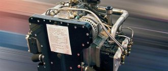
There are known developments of blowers/pumps based both on positive displacement compressors and on centrifugal ones. An example of the first option is the Soviet automotive diesel engines YaAZ-204 and YaAZ-206. An example of the second option is the Soviet/Ukrainian 5TDF multi-fuel tank engine. At the same time, the property of centrifugal compressors to increase boost pressure with increasing speed can also be used to boost the engine at high speeds. The presence of a blower/pump does not negate the possibility of supplementing such a two-stroke engine with a turbocharger, the task of which is to boost the engine in its purest form. An example of such engines with and without turbocharging would be the structurally identical locomotive diesel engines 10D100 and 2D100 of diesel locomotives TE10 and TE3.
With mechanical charging, the compressor is driven by the engine, the ratio of engine speed to compressor speed (unless a variable gear ratio is used, which occurs in exceptional cases) remains constant. The operating points on the characteristic are determined by the intersection points of the lines corresponding to the constant speeds of the engine and compressor, the location of which in relation to each other is determined by the gear ratio. Typically, the gear ratio i between the speed of a given engine and the compressor used for charging is determined so that at the full load point the pressure ratio required for a given mean effective pressure is achieved. All other operating points are obtained at variable speed from the characteristics shown in Fig. 6.1 and 6.2.In Fig. Figure 6.1 shows the characteristics of a four-stroke engine with mechanical supercharging, carried out using a positive displacement compressor. The point of intersection of the line of full engine rotation speed p with the line of full compressor rotation speed pk = ip gives the full load operating point indicated by a circle. As the engine speed decreases, the boost pressure along the operating mode line also decreases. The course of this latter strongly depends on the actual characteristics of the compressor. The decrease in boost pressure with a decrease in engine speed would be minimal if the compressor feed ratio with a decrease in rotation speed increased more than the engine filling ratio.
From Fig. 6.1 it can be seen that with an increase in the gear ratio and a decrease in valve overlap, under other constant conditions, the line of operating points moves upward.
The combined operation of a mechanically driven centrifugal compressor with an engine is shown in Fig. 6.2. It follows from the figure that the boost pressure drops significantly more with decreasing rotation speed than in the case of using a positive-displacement supercharger, which is explained by the nature of the dependence of the degree of pressure increase on the rotation speed.
From the point of view of the relationship in different areas of application between the torque Me of the engine and its rotational speed n, they are distinguished:
1) operation at a constant speed: n = const, Ме = var, for example, drive of electric generators;
2) work on the propeller characteristic: Me ~ n2, for example, drive of fixed pitch propellers on ships and aircraft;
3) work on automobile characteristics: n = var, Ме = var, for example, drive cars and diesel locomotives.
Torque is proportional to the mean effective pressure and can be expressed in terms of it.
Since in the first case there is only one operating point, which does not depend on the load, then, from a performance point of view, mechanical compressors of positive displacement and centrifugal types are equally good for this operating mode. The choice is determined by manufacturing costs and pressure and efficiency values.
In the second case, the boost pressure drops more with decreasing engine speed with a mechanically driven centrifugal compressor than with a positive displacement supercharger. This is not a disadvantage, since the boost pressure, if high enough at full load, will be sufficient at part load, since the mean effective pressure decreases significantly as the speed decreases. A significant reduction in boost pressure in this case is even desirable, since ensuring high boost pressure is associated with increased engine power consumption and, consequently, additional fuel consumption; therefore, in those modes where increased boost pressure is not required, it is better not to create it.
In this regard, centrifugal compressors are more suitable for mechanical supercharging of engines operating on a screw characteristic.
In the third case, a high torque is required at low engine speeds, if possible even a torque that increases with decreasing speed (torque reserve), in order to at least partially absorb the increasing resistance to movement at low speeds without resorting to to changing gears. A centrifugal compressor is not suitable for this; a positive displacement compressor is more suitable, although its boost pressure, which remains constant as the rotation speed decreases, can only be maintained in a limited range of rotation speeds.
Since two-stroke engines, unlike four-stroke engines, have only one flow line independent of the engine speed (the throttling line, since the engine resistance can be considered as the resistance of an orifice of constant cross-section), their performance characteristics for different types of compressors do not differ fundamentally from each other.
For a positive displacement compressor, the n = const lines are steep, and the volumetric air flow rate is approximately proportional to the rotational speed. These lines intersect the parabola of air volume flow through the engine at a pressure that increases approximately quadratically with increasing speed (Fig. 6.3). For a centrifugal compressor, pressure increases quadratically with increasing rotation speed.
With variable back pressure at the engine outlet, positive displacement and centrifugal compressors behave differently in the case of a two-stroke engine, which is due to the different locations of the lines of constant compressor rotation speeds. This must be taken into account, for example, on engines with a turbocharger and mechanically driven piston pumps connected in parallel. Based on the above, the behavior of an engine with mechanical supercharging can also be considered under other conditions, for example in the case of a variable gear ratio between the engine and the compressor.
Electric supercharger
Scheme of a combined supercharger consisting of a turbine, motor-generator, compressor and battery.
The operation of the boost in the turbocharger mode is constant, in the turbocharger and electric supercharger modes it is intermittent. The operating principle of an electric supercharger (electrically driven supercharger) is based on the use of electricity from the vehicle's on-board electrical network to drive the compressor. The fundamental design is generally the same - a high-speed electric motor and a centrifugal compressor connected to it by a common shaft.
Such superchargers have become widespread on gasoline engines of passenger cars in recent years, due to the widespread introduction of on-board electrical networks with a relatively high voltage (~50V) and the inclusion of powerful generators, high-capacity batteries and capacitors in the power unit. In this case, electric superchargers are only part of the overall supercharging unit and are combined with a turbocharger (one or two) to work together as part of the supercharging function. The activation of the electric supercharger here is usually limited to transient operating modes of the engine itself, and primarily to those in which the efficiency of the turbocharger is low, for example, spinning up the engine from idle speed. Electric superchargers are not used as a permanent source of boost, due to significant losses in converting the mechanical energy of the internal combustion engine into electrical energy to power the electric motor and again into mechanical energy to operate the compressor.
Mechanical engine charging: what you need to know
Let's start with the fact that installation of any type of supercharger (mechanical or turbocharging) is possible on both injection and carburetor engines. In both cases, a number of modifications to the power unit are expected, however, installing a turbine on the engine is somewhat more difficult and expensive compared to a compressor.
It becomes clear that a mechanical supercharger is a more affordable way to increase engine power; such a solution is easier to install on the engine, and the work can even be done independently. At the same time, the general principle of operation of the supercharger is quite simple.
The device can actually be compared to an attachment (generator, power steering pump or air conditioning compressor), that is, the unit is driven by the engine. As a result of the operation of a mechanical compressor, the air is compressed and enters the cylinders under pressure.
This allows the cylinders to be better purged (ventilated) from exhaust gas residues, cylinder filling is significantly improved, the amount of air in the combustion chamber increases, which makes it possible to burn more fuel and increase engine power.
Also, the compressor has a direct dependence on engine speed. The more the engine is revved, the more air is supplied to the combustion chambers and, accordingly, the power increases. At the same time, there is no pronounced effect of turbojam (turbolag), which is found on turbocharged engines. Turbo lag manifests itself in the form of a failure at low speeds, when the exhaust energy is not yet enough to spin the turbine and create the necessary pressure to effectively supply air to the cylinders.
Links
- [yamotorist.ru/index.php/kontent/turbonadduv Turbocharger and its comparison with a mechanical compressor]
- Article “Supercharging, superchargers and a little history”
- Article “What is turbocharging”
- Diesel with four superchargers developed by BMW
- Volumetric superchargers for American Ford models
- Electric supercharging developed by Audi
- 2020 Mazda SkyActive X supercharged car engine (1)
- 2020 Mazda SkyActive X supercharged car engine (2)
- Combined supercharging for gasoline engines developed by Volvo
- Combined supercharging for diesel engines developed by Mazda
- Garrett supercharger with dual turbine and electric motor drive
| This is a preliminary article about cars. You can help the project by adding to it. |
| Some external links in this article lead to sites listed as spam. These sites may infringe copyright, be considered non-authoritative sources, or be otherwise banned from Wikipedia. Editors should replace such references with references to compliant websites or bibliographic references to printed sources, or remove them (perhaps along with the content they support). List of problem domains
|
Turbo air blower
This approach to providing the engine with additional air is the most popular. It is used for both diesel and gasoline engines. The principle on which such a supercharger operates is clear from the figure below:
In fact, it is a combination of two devices - a turbine, which uses the energy of exhaust gases, and a compressor. Here it should immediately be noted that the turbo mode, used to increase the power of diesel engines, is used much more often than forcing air in gasoline engines. In them, the increase in pressure is limited by the appearance of detonation, and the introduction of a turbo mode requires the adoption of special protective measures.
The use of exhaust gas energy is associated with a whole range of problems, primarily with the materials used. Turbine blades must withstand temperatures of up to a thousand degrees, and their rotation speed often exceeds ten thousand revolutions per minute. However, the turbo mode, in which additional air enters the diesel, makes its operation easier.
Based on the stated features, the best way to supercharge a turbo will be at high engine speeds, when the turbine is strongly spun up. Another feature of this mode is the so-called delay. When you press the pedal sharply, some time passes until the boost in turbo mode kicks in, which causes a dip in performance.
To bypass it, special technical solutions are used. One possible option would be to use two turbochargers, one of which operates at low speeds and the other at high speeds. Each of the automakers solves this problem in its own way - some use a powerful supercharger that provides excessive air flow in all modes and, if necessary, dumps the excess, some use several small superchargers instead of one large one, some implement various combinations of two first options.
However, the turbo mode is often implemented on older cars, including the VAZ family, although in this case electric boost is most often used.