Test "Main gear"
Budgetary professional educational institution
Omsk region
"Sedelnikovsky Agro-Industrial College"
TEST
«main gear»
MDK.01.02 “Design, maintenance and repair of automobiles”
PM. 01 Maintenance and repair of vehicles
by profession
01/23/03 Auto mechanic
Sedelnikovo, Omsk region, 2017
The purpose of these tests is to consolidate by students the knowledge acquired by studying theoretical material on the topic “Main Gear”, which is part of the MDK 01.02 “Design, maintenance and repair of motor vehicles” of the profession 01.23.03 “Auto mechanic”. The tests are compiled in accordance with the requirements of the program of the professional module PM.01 “Maintenance and repair of motor vehicles”, by profession 01/23/03 “Auto mechanic”, 1st year.
Test No. 10 «
Main gear"
1. The driven gear of the main gear is rigidly connected to...
a) driveshaft flange,
b) differential box,
c) semi-axis,
d) any of the above details?
2. Locking the center differential...
A) should be done after stopping the car, before starting to move,
B) is allowed to be performed when the vehicle is moving at any speed,
Q) Should this only be done while parked?
3. Which part of the final drive is rigidly connected to the cardan drive?
A) Drive bevel gear.
B) Driven bevel gear.
B) Leading or driven, depending on the design features of the bridge.
4. The final drive provides...
A) decrease in rotation speed and increase in torque,
B) increase in rotation speed and increase in torque,
B) reduction of rotation speed and reduction of torque,
D) increase in speed and decrease in torque?
5. The occurrence of slipping of one of the drive wheels is accompanied by an increase in the rotation speed of this wheel and ...
A) by reducing the torque supplied to it,
B) conservation of the torque supplied to it,
B) increasing the torque supplied to it,
D) an increase or decrease in the torque supplied to it, depending on the trajectory of the car?
6. If the torque supplied to one of the wheels of the drive axle decreases, then the torque on the opposite wheel of this axle...
A) will decrease
B) will increase
C) will not change?
7. Which of the following parts of the drive axle change their speed due to a change in the direction of the vehicle (entering a turn)?
A) Satellites.
B) Main gear driven gear.
B) Differential box.
8. What kind of oil is poured into the rear axle housing:
A) motor
B) transmission
C) motor or transmission depending on the make of the car?
9. In what cases do the differential pinions not rotate around their axes?
a) when one of the wheels slips
b) when the car is moving around turns
c) when driving on a straight and level road
10. Constant velocity universal joints can be ball or cam. Which of the following are used in the front drive axles of GAZ and UAZ vehicles?
a) cam
b) ball
c) both types
11. Which answer correctly identifies the main elements of a universal joint?
a) two forks, a cross, needle bearings
b) shafts with splined tips and supports
c) sliding fork, elastic rubber coupling, clamp
Sample answers:
| Question | 1 | 2 | 3 | 4 | 5 | 6 |
| Answer | b | A | A | A | A | A |
| Question | 7 | 8 | 9 | 10 | 11 | |
| Answer | A | b | V | b | A |
Test assessment criteria:
Rating “excellent” 10-11 correct answers or out of 11 proposed questions;
Rating “good” 8-9 correct answers or out of 11 proposed questions;
Rating “satisfactory” 6-7 correct answers out of 11 proposed questions;
Rating unsatisfactory” 0-5 correct answers out of 11 proposed questions.
Bibliography
Kuznetsov A.S. Car maintenance and repair: at 2 o'clock - a textbook for beginners. prof. education / A.S. Kuznetsov. - M.: Publishing House, 2012.
Kuznetsov A.S. Car repair mechanic (motor mechanic): textbook. guide for beginners prof. education / A.S. Kuznetsov. – 8th ed., erased. – M.: Publishing House, 2013.
Auto mechanic / comp. A.A. Khannikov. – 2nd ed. – Minsk: Modern School, 2010.
Vinogradov V.M. Maintenance and repair of automobiles: Basic and auxiliary technological processes: Laboratory workshop: textbook. aid for students institutions prof. education / V.M. Vinogradov, O.V. Khramtsova. – 3rd ed., erased. – M.: Publishing House, 2012.
Petrosov V.V. Car and engine repair: A textbook for students. Institutions environment. Prof. Education / V.V. Petrosov. – M.: Publishing House, 2005.
Karagodin V.I. Car and engine repair: A textbook for students. Institutions environment. Prof. Education / V.I. Karagodin, N.N. Mitrokhin. – 3rd ed., erased. – M.: Publishing House, 2005.
Korobeichik A.V. k-68 Car repair / Series “Motorist’s Library”. Rostov n/a: “Phoenix”, 2004.
Korobeichik A.V. K-66 Car repair. Practical course / Series “Motorist's Library”. – Rostov n/a: “Phoenix”, 2004.
Chumachenko Yu.T., Rassanov B.B. Automotive workshop: A manual for performing laboratory and practical work. Ed. 2nd, add. – Rostov n/d: Phoenix, 2003.
Elephant Yu.M. S-48 Auto mechanic / Series “Textbooks, teaching aids”. – Rostov n/a: “Phoenix”, 2003.
Zholobov L.A., Konakov A.M. Zh-79 Design and maintenance of cars of categories “B” and “C” using the example of VAZ-2110, ZIL-5301 “Bychok”. Series "Motorist's Library". – Rostov-on-Don: “Phoenix”, 2002.
Four-wheel drive. Why split torque?
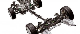
All-wheel drive - why share torque between axles? First of all, in this case, the most efficient use of engine power is ensured in any driving mode, and controllability is improved, especially on slippery surfaces. Until the mid-60s, four-wheel drive vehicles were intended only for special purposes: off-road driving, construction and agricultural work, and other special needs. As a rule, with rare exceptions, most of these cars were modifications of ordinary cars, but with a 4x4 wheel arrangement. This forced designers to integrate drives to the front axle into the existing transmission design. Cars with all driving wheels were designed to be driven by specially trained drivers who knew which lever to turn under what circumstances. It was considered normal when the driver’s incorrect sequence of actions or failure to perform certain operations led to transmission failure. Everything changed radically by the 80s. By that time, the standard of living of the population of most Western countries had increased significantly and people had more free time. The demand for goods intended for outdoor activities has increased, and new SUVs designed for non-professionals have appeared. To the credit of the designers, they developed original transmissions with easier engagement of the front axle and the reduction row in the transfer case, eliminating unit breakdowns due to driver error. Chassis of a modern all-wheel drive vehicle. Why share torque between axles? If there is no inter-axle power distribution (center differential or disconnecting mechanism), it is necessary to disable the front axle so that the front and rear wheels can rotate at different angular speeds. According to driving conditions, it is required that the wheels of both the front and rear axles, and the wheels of one axle, can rotate at different frequencies and travel different paths. Various factors influence the change in wheel path: tire slip, tire slip angles, air pressure, wheel load, suspension kinematics. It is obvious that the ratio between the paths traversed by the wheels of the front and rear axles also changes while driving. This circumstance excludes the possibility of using different gear ratios in the main gears of bridges to compensate for the difference in the traversed paths. Wheels of different axles of cars, kinematically rigidly connected to one another, have the same angular velocities when rotating. For example, in an amphibian that floats on water due to the rotation of its wheels, all wheels rotate at the same angular velocity. It's a different matter on a hard road surface. In this case, when driving a car with all-wheel drive (in the absence or blocking of center differentials), conditions may arise in which the wheels of different axles will try to move at different linear speeds, and the rigid mechanical connection between them will become an obstacle to achieving this. The turning geometry of a 4x4 vehicle. During rectilinear motion, the described phenomenon can be caused, for example, by the difference in the rolling radii of interconnected wheels. The rolling of the wheels in this case should be accompanied by a relative movement of the points of contact of the tire along the road surface (with sliding or slipping). The same is possible with the same rolling radii, but when driving on a road with an uneven surface or when turning. The sliding or slipping of tires that occurs under these conditions is accompanied by increased tire wear, wear of transmission mechanisms and wasteful expenditure of engine energy to move the vehicle. In order for the wheels to roll without harmful accompanying phenomena in the transmission, in addition to inter-axle differentials, inter-axle differentials are installed. When great freedom gets in the way. In an SUV with a differential between the axles, the satellites are constantly in motion, redistributing torque between the front and rear drive axles. It would seem that everything is fine. However, a powerful car may lose mobility at the moment when the wheels of one of the bridges lose traction and begin to slip. In such a situation, a conventional differential will not be able to transmit the amount of torque required for movement to the rear wheels resting on solid ground. That is why the excess freedom of satellites has to be limited. Forced locking center differential of the Niva VAZ 2121. In order to increase cross-country ability, center differentials with forced locking are installed on SUVs. An example of such a solution is our Niva VAZ 2121, equipped with a transfer case with a forced locking center differential. The car driver uses the blocking to overcome a difficult section of the road. When returning to the highway, the center differential must be unlocked. Devices similar in operating principle are now not uncommon, while the locking differential drive is constantly being improved. In modern units, blocking occurs under the action of pneumatics and hydraulics, while more and more trouble is removed from the driver. On modern all-wheel drive vehicles, instead of or in conjunction with a center differential, viscous couplings, more modern GeroDisc couplings and Haldex couplings are used.
The invention relates to the field of mechanical engineering and can be used in gearboxes to increase torque on the shaft.
A device for increasing torque is known - a gear train, including a gear and a gear. Torque on the driven gear Mk; determined by dependency
where Msh is the torque on the drive gear, which imparts rotation to the gear;
u is the gear ratio.
In the known device, as the torque increases, the rotational speed of the gear wheel decreases.
The object of the present invention is to increase the torque on a gear without increasing the gear ratio.
This goal is achieved in that the proposed device contains kinematically connected or interconnected gear wheels mounted with the possibility of rotation, an additional shaft installed in a support with a gear or gears kinematically connected to the gear wheels, and a means capable of creating pressure on the additional shaft, wherein the support the additional shaft is installed with the ability to rotate relative to the axis of rotation of the gear wheels or move in the tangential direction, and one gear of the additional shaft is kinematically connected to the connected gear wheel by means of one or more idler gears installed on the additional support. Additional shaft support is a body in which the additional shaft is mounted on bearings.
Having the ability to create pressure on the additional shaft, the means can be made in the form of a two-stage coaxial gear drive.
Having the ability to create pressure on the additional shaft, the means can also be made in the form of a torsion, compression, or extension spring.
A flywheel is installed on an additional shaft.
The device can be equipped with an intermediate gear installed for rotation relative to the axis of rotation of the gear wheels, which is in internal or external engagement with the idler gear and in external or internal engagement, respectively, with the gear of the additional shaft.
The axis of rotation of the additional shaft can be located in a horizontal plane passing through the axis of rotation of the gear wheels.
The device can be additionally equipped with one or more additional shafts and gears or gears and flywheels installed in spring-loaded supports.
In the described device, the pressure created by the means on the additional shaft creates circumferential forces on the teeth of the gear or gears of the latter, acting on the teeth of kinematically connected gears in one direction or on the teeth of connected gears in opposite directions. Under the influence of the mass of the rotating additional shaft and the gears mounted on it, a redistribution of circumferential forces occurs. The circumferential force acting in the direction of rotation of the gear increases, and the circumferential force acting in the direction opposite to the direction of rotation of the gear decreases. As a result, an additional torque acting in the direction of rotation of the gears is created on the gears.
The implementation of the means capable of creating pressure on the additional shaft in the form of a two-stage coaxial gear transmission increases the rotation speed of the additional shaft and, consequently, additional torque on the gear wheels.
Providing the means to create pressure on the additional shaft in the form of springs simplifies the design of the device.
A flywheel mounted on an additional shaft increases additional torque on the gears.
Equipping the device with an intermediate gear increases the reliability of its operation. The axis of rotation of the additional shaft can be located with an angular displacement relative to the axis of rotation of the idler gear.
The location of the axis of rotation of the additional shaft in a horizontal plane passing through the axis of rotation of the gears increases the additional torque on the latter by the maximum amount.
Additional supply of the device with additional shafts installed in spring-loaded supports increases the torque on the gears and allows you to create individual pressures on the additional shafts.
In fig. 1 shows the proposed device, in which the means creating pressure on the additional shaft is made in the form of a two-stage coaxial gear drive; in fig. 2 - the proposed device, in which the means creating pressure on the additional shaft is made in the form of a two-stage coaxial gear transmission, and the gears are installed on the low-speed shaft of the latter; in fig. 3 - intermediate gear, which is in internal engagement with the idler gear and in external engagement with the additional shaft gear; in fig. 4 - the proposed device, in which the means creating pressure on the additional shaft is made in the form of a twisted torsion spring; in fig. 5 - the proposed device, in which the means creating pressure on the additional shaft is made in the form of a twisted torsion spring, and the gear of the additional shaft, in particular, is kinematically connected to the connected gear through several idler gears; in fig. 6 - proposed device in which the gears are kinematically connected to each other; in fig. 7 - a proposed device in which the rotation axes of kinematically interconnected gears and an additional shaft intersect at right angles.
Shown in FIG. 1 device contains a gear 2 and a gear 3 mounted on rolling bearings on a fixed axis 1, a support for an additional shaft 4 mounted on sliding bearings on an axis 1, in which an intermediate shaft 5 with a gear 6 and a gear 7 and an additional shaft are mounted on rolling bearings 8 with gears 9 and 10 and flywheel 11 mounted on it.
Gear 6 and gear 7 are in mesh with gear 2 and gear 3, respectively. The gear 9 of the additional shaft is in internal engagement with the gear wheel of the device 12, and the gear 10 of the additional shaft is kinematically connected by means of an idler gear 14 installed on the additional support 13 with the gear wheel of the device 15. The gear wheels of the device 12 and 15 are placed on rolling bearings on axis 1 and connected to gear 3. Additional support 13 is connected to a fixed axis 1.
Shown in FIG. 2, the device contains gears 17 and 18 mounted on a fixed axis 16 on rolling bearings, connected to each other by means of a bushing/hollow shaft, a gear 19 mounted on plain bearings on axis 16, a support for an additional shaft 20, in which an intermediate shaft is mounted on rolling bearings 21 with gear 22 and gear 23 and an additional shaft 24 with gears 25 and 26 and a flywheel 27 mounted on it.
Gear 22 and gear 23 of the intermediate shaft are in mesh with gear 17 and gear 19, respectively. The gear 25 of the additional shaft is in internal engagement with the gear wheel of the device 18, and the gear 26 of the additional shaft is kinematically connected through the idler gear 29 installed on the additional support 28 with the gear 17. The latter is used as a gear of the gear transmission stage. Additional support 28 is connected to a fixed axis 16.
Shown in FIG. 3, the intermediate gear 30 is mounted on a double rolling bearing on a sleeve connecting the gears of the device 31 and 32 to each other, and is in external engagement with the gear of the additional shaft 33 and in internal engagement with the idler gear 34. The gear 31 is in internal engagement with additional shaft gear 35.
Shown in FIG. 4, the device contains interconnected gear wheels 37 and 38 mounted on a fixed axis 36 on rolling bearings, a support for an additional shaft 39 mounted on sliding bearings on an axis 36, in which an additional shaft 40 is mounted on rolling bearings with gears 41 and 42 mounted on it. And a flywheel 43, an additional support 44 connected to the axis 36, on which a gear 45 and an idler gear 46 are mounted, and a twisted torsion spring 47 placed on the axis 36, interacting with the supports 39 and 44.
Gear 45 is in external engagement with gear 37, idler gear 46 is in external engagement with gear 37 and additional shaft gear 42, and gear 41 is in internal engagement with gear 38.
Shown in FIG. 5, the device contains interconnected identical gears 49 and 50 mounted on a fixed axis 48 on rolling bearings, a support for an additional shaft 51 mounted on a sliding bearing on axis 48, in which an additional shaft 52 is mounted on rolling bearings with a gear 53 mounted on it and a flywheel 54, an additional support 55 connected to the axis 48, on which a gear 56 and identical idler gears 57, 58 and 59 are mounted, and a twisted torsion spring 60 placed on the axis 48, interacting with the support 51 and a ring 61 connected to the axis 48.
Gear 56 is in mesh with gear 50, the additional shaft gear 53 is in mesh with gear 49 and is kinematically connected through idler gears 58, 59 and 57 with gear 50.
Shown in FIG. 6, the device contains gears 63 and 64 mounted on a fixed axis 62 on rolling bearings, an intermediate shaft support 65 connected to the axis 62, in which an intermediate shaft 66 is mounted on rolling bearings with gears 67 and 68 mounted on it, mounted on an axis 62 on sliding bearings, a support for an additional shaft 69, in which an additional shaft 70 is mounted on rolling bearings with gears 71 and 72 mounted on it and a flywheel 73 and a twisted torsion spring 74 placed on the axis 62, interacting with supports 65 and 69.
The intermediate shaft gear 67 is in external mesh with gear 63, and gear 68 is in internal mesh with gear 64. The additional shaft gear 72 is in external mesh with gear 63 and gear 71 is in internal mesh with gear 64.
Shown in FIG. 7, the device contains identical bevel gears 76 and 77 mounted on a fixed axis 75 on rolling bearings, a support for an additional shaft 78 mounted on an axis 75 on a plain bearing, in which an additional shaft 79 is mounted on rolling bearings with a bevel gear 80 and a flywheel mounted on it 81, an intermediate shaft support 82 connected to the axis 75, in which an intermediate shaft 83 is mounted on rolling bearings with a bevel gear 84 mounted on it, and a twisted torsion spring 85 placed on the axis 75, interacting with the supports 78 and 82.
The intermediate shaft bevel gear 84 and the auxiliary shaft bevel gear 80 mesh with bevel gears 76 and 77.
Shown in FIG. 1 device works as follows. Gear 2, through gear 6 and gear 7 of the intermediate shaft, imparts rotational motion to gear 3 and the gears of the device 12 and 15 connected to the latter. Gears 12 directly and 15, through idler gear 14, impart rotational motion to the gears of the additional shaft 9 and 10 and mounted on additional shaft for flywheel 11.
The torque on the support of the additional shaft 4, acting in the direction of rotation of the gear 3, creates pressure on the additional shaft 8. This pressure, in turn, creates circumferential forces on the gear teeth of the additional shaft 9 and 19, acting on the teeth of the gear wheels of the device 12 and 15 The values of circumferential forces without taking into account the influence of the mass of rotating parts, in particular, with very slow rotation of the additional shaft, are determined from the following dependencies
where P is the pressure on the additional shaft 8,
P1 and P2 are circumferential forces on the teeth of gears 9 and 10, respectively,
d1 and d2 are the pitch diameters of gears 9 and 10, respectively. The circumferential forces P1 and P2 create torques of equal magnitude on the gear wheels of the device 12 and 15, respectively, acting in opposite directions. In this case, the torque on gear 3 is equal to (1)
.
When the rotation speed of the additional shaft 8 increases under the influence of the mass of the latter, gears 9 and 10 and flywheel 11, a redistribution of the circumferential forces P1 and P2 occurs. For example, depending on the direction of rotation, the circumferential force on the teeth of gear 9 acting on the teeth of gear 12 increases, and the circumferential force on the teeth of gear 10 acting on the teeth of gear 15 decreases. Accordingly, the torques on the gears of the device increase and decrease. As a result, an additional torque equal to the difference between these torques is created on the interconnected gear wheels 12 and 15. In this case, the actual torque on gear 3 connected to gears 12 and 15 is determined by the dependence
where the value q is greater than one and less than the gear ratio u (1
Shown in FIG. 2 the device works as follows. Gear 17, through gear 22 and gear 23 of the intermediate shaft, communicates the rotational motion of gear 19. Gears 18 directly and 17, through idler gear 29, communicate rotational motion to the gears of the additional shaft 25 and 26 and the flywheel 27 mounted on the additional shaft.
The torque on the support of the additional shaft 20, acting in the directions of rotation of the gear 17, creates pressure on the additional shaft 24. This pressure creates circumferential forces on the teeth of the gears 25 and 26, acting on the teeth of the gears of the device 18 and 17, respectively. The values of circumferential forces without taking into account the influence of the mass of rotating parts are determined from dependencies (2) and (3). The circumferential forces, in turn, create torques of equal magnitude on the gear wheels of the device 18 and 17, acting in opposite directions. In this case, the torque on gear 19 is determined by dependence (1).
Under the influence of the mass of the rotating additional shaft 24, gears 25 and 26 and flywheel 27, a redistribution of the circumferential forces determined by dependencies (2) and (3) occurs. For example, depending on the direction of rotation, the circumferential force on the teeth of gear 25 acting on the teeth of gear 18 increases, and the circumferential force on the teeth of gear 26 acting on the teeth of gear 17 decreases. Accordingly, the torques created by the circumferential forces on the gears 18 and 17 increase and decrease. As a result, an additional torque equal to the difference of these torques is created on the interconnected gears. In this case, the torque on gear 19 increases by an amount equal to the quotient of the additional torque divided by the gear ratio. The actual torque on gear 19 is determined by the dependence
Shown in FIG. 4, the proposed device works as follows. Gear 45 imparts rotational motion to the interconnected gears 37 and 38. Gears 38 directly and 37 through idler gear 46 impart rotational motion to the gears of the additional shaft 41 and 42 and the flywheel 43 mounted on the additional hall.
The twisted torsion spring 47, through the support of the additional shaft 39, creates a constant pressure on the additional shaft 40. This pressure, in turn, creates circumferential forces on the teeth of the gears 41 and 42, acting on the teeth of the gears 38 and 37, respectively. The values of circumferential forces without taking into account the influence of the mass of rotating parts, in particular, in a static state, are determined from dependencies (2) and (3). The resulting circumferential forces create torques of equal magnitude on gears 38 and 37 acting in opposite directions. In this case, the torque on the gear 37 is determined by dependence (1).
Under the influence of the mass of the rotating additional shaft 40, gears 41 and 42 and flywheel 43, a redistribution of the circumferential forces determined by dependencies (2) and (3) occurs. For example, depending on the direction of rotation, the circumferential force on the teeth of the gear 41 acting on the teeth of the gear 38 increases, and the circumferential force on the teeth of the gear 42 acting on the teeth of the gear 37 decreases. Accordingly, the torques created by the circumferential forces on the gears 38 and 37 increase and decrease. As a result, an additional torque acting in the direction of rotation of the latter is created on the gears connected to each other, equal to the difference of these torques. The actual torque on the interconnected gear wheels 38 and 37 is determined by the dependence
where the value of q1 is greater than the gear ratio u (q1>u), is determined experimentally.
Shown in FIG. 5, the proposed device works as follows. Gear 56 imparts rotational motion to interconnected identical gears 50 and 49. Gears 49 directly and 50. Through identical idler gears 57, 59 and 58 communicate rotational motion to the gear of the additional shaft 53 and the flywheel 54.
The twisted torsion spring 60, through the support of the additional shaft 51, creates a constant pressure on the additional shaft 52. This pressure, in turn, creates circumferential forces on the gear teeth of the additional shaft 53, acting on the teeth of the gears 49 and 50. Obtained without taking into account the influence of the mass of the rotating parts according to dependencies (2) and (3), equal circumferential forces create torques of equal magnitude on gears 49 and 50 acting in opposite directions. In this case, the torque on the gear 50 is determined by dependence (1).
Under the influence of the mass of the rotating additional shaft 52, gear 53 and flywheel 54, a redistribution of equal circumferential forces determined from dependencies (2) and (3) occurs. Depending on the direction of rotation, the circumferential force on the teeth of the gear 53, acting, for example, on the teeth of the gear 49, increases, and the circumferential force on the teeth of the gear 53, acting through the idler gears 58, 59 and 57 on the teeth of the gear 50, decreases. Accordingly, the torques created by the circumferential forces on the gears 49 and 50 increase and decrease. As a result, an additional torque equal to the difference between these torques is created on the interconnected gears. The actual torque on the interconnected gears 49 and 50 is determined by dependence (5).
Shown in Fig. 6, the proposed device works as follows. Intermediate shaft gears 67 and 68 impart rotational motion to gears 63 and 64, respectively. The latter is the rotational movement of the executive shaft gears 72 and 71 and the flywheel 73.
The twisted torsion spring 74, through the support of the additional hall 69, creates a constant pressure on the additional shaft 70. The pressure created by the torsion spring creates circumferential forces on the gear teeth of the additional shaft 72 and 71, acting through gears 63 and 64 on the teeth of the intermediate shaft gears 67 and 68. Values circumferential forces without taking into account the influence of the mass of rotating parts are determined from dependencies (3) and (2). The circumferential forces obtained from these dependencies create torques of equal magnitude on gears 67 and 68 acting in opposite directions. In this case, the torque on gears 63 or 64, depending on the load on them, is determined according to the dependence.
Under the influence of the mass of the rotating additional shaft 70, gears 71 and 72 and flywheel 73, a redistribution of the circumferential forces determined from dependencies (2) and (3) occurs. Depending on the direction of rotation of the gears of the additional shaft, the circumferential force, for example, on the teeth of gear 71, acting on the teeth of gear 64, increases, and the circumferential force on the teeth of gear 72, acting on the teeth of gear 63, decreases. Accordingly, the torques created by the circumferential forces on the gears 68 and 67 increase and decrease. As a result, an additional torque acting in the direction of rotation of the gears 68 and 67 is created on the gears of the intermediate shaft 68, equal to the difference of these torques. The actual torque on gears 63 or 64, depending on the load on them, is determined by dependence (5).
Shown in FIG. 7 the device works as follows. The intermediate shaft gear 84 imparts rotational motion to the gears 76 and 77. The latter is the rotational motion of the additional shaft gear 80 and the flywheel 81.
The twisted torsion spring 85, through the support of the additional shaft 78, creates a constant pressure on the additional shaft 79. The created pressure, in turn, creates circumferential forces on the gear teeth of the additional shaft 80, acting through gears 76 and 77 on the gear teeth of the intermediate shaft 84. Circumferential values forces without taking into account the influence of the mass of rotating parts are determined from dependencies (2) and (3). The equal circumferential forces on the teeth of gear 80 obtained from these dependencies create torques of equal magnitude acting in opposite directions on gear 84. In this case, the torque on gears 76 or 77, depending on the load on them, is determined by dependence (1).
Under the influence of the mass of the rotating additional shaft 79, gear 80 and flywheel 81, a redistribution of the circumferential forces determined by dependencies (2) and (3) occurs. Depending on the direction of rotation, the circumferential force on the teeth of gear 80, acting, for example, on the teeth of gear 77, increases, and the circumferential force on the teeth of gear 80, acting on the teeth of gear 76, decreases. Accordingly, the torques created by the circumferential forces on gear 64 increase and decrease. As a result, an additional torque equal to the difference between these torques is created on the latter. The actual torque on gears 76 or 77, depending on the load on them, is determined by dependence (5).
In the proposed device, the means capable of creating pressure on the additional shaft can be made in the form of a two-stage gear transmission, in which the axes of rotation of the gear wheel and stage gear are located parallel or intersect at an angle of 90°.
A pneumatic cylinder or a hydraulic cylinder can be used as a means capable of creating pressure on the additional shaft.
One or more additional shafts with gears or with gears and flywheels can be additionally installed in the support of the additional shaft. This reduces the load on the gears and increases the torque on the gears of the device.
The teeth of the gears and gear wheels of the device can be arranged along helical lines. This ensures smooth operation and continuity of the action of circumferential forces on the gear teeth on the gear teeth.
In the case of parallel or serial connections between several devices, for example, those shown in Fig. 1, the torque on gear 3 /gears 12 and 15/ increases exponentially. The magnitude of the torque can be determined by the formula
where k is the number of devices connected (in parallel or in series);
Mshk - torque on gear 3 of the last device;
Msho - torque on the gear / in Fig. 1 is not shown, imparting rotational movement to the gear 2 of the first device.
In this case, the rotation speeds of the gears are equal to each other.
Transmission: device
First of all, many people mistakenly believe that the transmission is the gearbox. Actually this is not true. In fact, every element that is responsible for connecting the engine with the drive wheels is part of the vehicle's transmission. The transmission itself in a car is responsible for performing the following tasks:
- transmission of torque from the engine to the drive wheels;
- change (conversion) of torque value;
- changing the direction of torque;
- redistribution of torque between the wheels.
There are several types of transmission. At the same time, as of today, a mechanical transmission is most actively used on cars, which converts the mechanical energy obtained as a result of engine operation. Hydromechanical transmission is also widespread, where the torque changes automatically (automatic transmission).
To put it simply, today the most common transmissions are manual transmission and automatic (hydromechanical automatic transmission). Each of these types of transmissions differs in its design, has both advantages and disadvantages, but their main task invariably remains the receipt, conversion and transmission of torque from the engine to the drive wheels of the machine.
Let's move on. All transmissions (both automatic and manual) differ in the type of drive. More precisely, the driving wheels can be the front, rear, or all wheels of the car at once.
If only the front wheels are driven, then it is a front-wheel drive car, if the rear axle is driven, then the car is rear-wheel drive, and if all wheels are driven, then it is an all-wheel drive car. Depending on the type of drive, the transmission design also differs significantly (in the number of elements, in the design of the device, etc.).
The transmission of a rear-wheel drive car has a clutch, gearbox (gearbox), cardan drive, final drive, differential, and axle shafts.
- The clutch allows you to smoothly disconnect and connect the engine to the transmission, which is necessary for changing gears, as well as in order to avoid high loads on transmission parts.
- The gearbox (gearbox) is the basis of the transmission and serves to convert torque, change the speed of movement (forward movement), the direction of movement (reverse gear), and also to separate the engine and transmission (neutral gear).
- The cardan transmission is responsible for transmitting torque from the secondary shaft of the gearbox to the main gear shaft, which are located at an angle relative to each other. The main gear allows you to increase the torque on the wheels and transmit it to the axle shafts of the drive wheels. Rear-wheel drive cars have a hypoid final drive, where the gear axes do not intersect each other.
- The differential distributes torque between the left and right drive wheels, allowing the axle shafts to rotate at different angular speeds. This is necessary to increase the stability of the car when cornering, difficult sections of the road, etc.
Currently reading:
Replacing tie rods and ends: what you need to know
Jun 21, 2020
What oil to fill in Kia Rio: what you need to know
Jun 21, 2020
On cars with front-wheel drive, some of the elements that are on rear-wheel drive cars are simply missing. In fact, there is no driveshaft. Front-wheel drive vehicles have CV joints (constant velocity joints) as well as drive shafts, better known as axle shafts. The main gear, as well as the differential, are installed in the gearbox housing.
We also recommend reading the article about what an all-wheel drive transmission is. From this article you will learn how a car's all-wheel drive (all-wheel drive transmission) works and works.
- The CV joint is an element that is necessary in order to transmit torque from the differential to the drive wheels. The transmission design of front-wheel drive cars often uses two internal CV joints (responsible for connecting to the differential), as well as two external ones (for connecting to the wheels). Between the indicated pairs of CV joints (external and internal), there are axle shafts.
As for all-wheel drive cars, in this case the transmission may differ in design, but it is based on a combination of front- and rear-wheel drive systems. Let us add that all-wheel drive can be permanent or connected. This transmission is the most complex in design and is distinguished by a large number of components, forming various all-wheel drive schemes for the vehicle.
Torque transmission at an angle
Cardan transmission
serves to transmit torque from one unit to another, the axes of the shafts of which may not coincide, change the crossing angle, allowing a change in the distance between the shafts. In cars, a cardan drive can be used to transmit engine torque in rear-wheel drive and all-wheel drive transmissions, in the steering system to transmit rotation from the steering wheel to the steering mechanism, as well as in the gear shift lever drive. The cardan transmission used in a car transmission consists of a pipe or solid rod, on one side of which a fixed fork is welded, on the other - a splined bushing with a movable fork.
The spline connection serves to compensate for changes in the length of the propeller shaft during suspension operation. When transmitting high torque, spline joints exhibit significant shear resistance. Therefore, to ensure high smooth operation of the transmission during suspension strokes on high-speed shafts loaded with high torques, instead of a splined connection, a high-speed movable constant velocity joint is used.
The driveshaft joints consist of two forks located in planes perpendicular to each other, connected by a cross with four needle bearings.
Balancing plates are welded to the propeller shaft pipe and are installed during dynamic balancing of the propeller shaft on a special stand. Elastic final drive and powertrain suspensions require a flexible connection at at least one end of the driveshaft. For this purpose, elastic disk rubber couplings with axial centering are used. Elastic disk couplings (elastic couplings) also help dampen torsional vibrations and isolate structural noise that occurs in cardan drives.
The length of a solid or tubular driveshaft has the greatest influence on its critical speed. Therefore, on all high-speed cars, dismembered driveshafts with an intermediate support are installed, consisting of two or three parts.
The intermediate support is a radial ball bearing, sealed on both sides and filled with long-lasting lubricant, which is mounted on the car body (frame) with the help of a vulcanized elastic rubber-metal holder.
The disadvantage of transmitting torque using a universal joint is that the angular velocity of the driven shaft changes with each revolution. To reduce this effect and the vibration it causes, when assembling cardan shafts, the forks at both ends are placed in the same plane. The second disadvantage of the cardan transmission is the limitation of the torque transmission angle.
The angle in the hinge during operation is from 0 to 12 degrees on trucks, and 0 to 4 degrees on passenger cars in running order. The design of the hinge allows the transmission of torque at an angle of up to 35 degrees, and with a centered double hinge from GWB, a torque of up to 12,000 N*m, with a maximum angle of up to 42 degrees.
“What kind of “moment” is this - torque? Who is he spinning? What is it needed for?" - the reader asks us.
Power characterizes the traction capabilities of the engine only indirectly. It is important for overclocking. To accelerate a car, work must be done. And power is the work done by the engine over a period of time. In other words, to accelerate quickly, for example to overtake or achieve a high top speed, you need to have more power. The more powerful the motor, the faster the acceleration.
However, the engine develops its greatest power only at speeds close to maximum. But almost no one drives like this every day. The driver needs a torquey engine that, when starting and accelerating, follows the gas pedal without straining. It is the ability to bear the load that provides the torque.
This is the force multiplied by the leverage of its application, which the engine can provide to the car to overcome certain movement resistances.
If the torque at low speeds is low, then it is difficult to move away, especially under load. Every driver knows that to start moving uphill, you need to press the gas harder (there is not enough torque).
There is another parameter that affects driving - engine elasticity (the ratio between the maximum power and maximum torque revolutions).
This ratio should be such that, in relation to the maximum power speed, the maximum torque speed is as low as possible. This will allow you to reduce and increase speed only by working with the gas pedal, without changing gears, and also drive in high gear at low speed.
You can practically evaluate the elasticity of a motor by checking the car’s ability to accelerate from 60 to 100 km/h in fourth gear. Moreover, this must be done with different loads. The smaller the difference between the acceleration of an empty and loaded car, the more elastic the engine.
Drawings for RF patent 2426021
The invention relates to the field of mechanical engineering. Currently, the transmission of torque between parallel drive and driven shafts, located one from the other at a distance of one meter to several meters, is carried out using a transmission shaft, which is installed, as a rule, perpendicular to them and is connected to each of them through angular gearboxes . A double rotation of the torque reduces the efficiency of the transmission, especially if the gears of the angular gearboxes are hypoid, the teeth of which roll in with some slip. The widely known method used in the construction of steam locomotives is never used. The driving wheel of a steam locomotive, which receives rotation through a connecting rod (crank drawbar in the terminology of steam locomotive engineering) from the piston of the steam engine, is connected by a coupling rod (coupling drawbar in the terminology of steam locomotive engineering) to another wheel and thus transmits torque to a parallel shaft. One of the reasons for the refusal to transmit torque using coupling connecting rods in modern vehicles should be the weight of the connecting rods, which increases in proportion to the distance between the shafts. The use of coupling connecting rods leads to the emergence of unbalanced forces, variable in magnitude and direction, which forces the installation of counterweights when using them, which significantly increase the weight of the structure. This can be seen from considering the design of the driving wheels of a steam locomotive. On the side of the coupling rod, the axle is connected to the wheel rim by spokes; on the opposite side, by a cast disk.
The invention is aimed at reducing the negative aspects of using coupling connecting rods.
The prototype of the device is based on the design set out in patent US 2203975 (A), 1940-06-11 (ipc B61C 9/04; B61C 9/00). In the description, it is proposed that in order to equalize the transmitted torque, the nearest axes of the wheels of two independent driving bogies of a steam locomotive should be made in the form of crankshafts with three cranks located at 120 degrees, connecting them with connecting rods.
The arrangement of the cranks at 120 degrees allows torque to be transmitted constantly. When transmitting torque with one or two connecting rods, there are points at which the transmitted torque is zero, which in most cases is undesirable. The prototype described crankshafts, but eccentrics with an eccentricity equal to the size of the crank can replace crankshafts, and can also be used interspersed if necessary. IPC F16C 3/04 considers crankshafts, shafts with eccentrics, cranks, eccentrics, that is, some of their properties are considered in one subgroup. Thus, in the future, when describing actions with eccentrics, similar possibilities are implied with cranks (crankshafts) and vice versa.
Currently, connecting rods perceive alternating loads. They are made of alloy steel with a specific strength of up to 100 kg per square millimeter, that is, close to the maximum tensile strength for this material. At the same time, there are tensile steel products with a specific strength of 200 kg per square millimeter - this is steel wire for ropes.
It is proposed to increase the specific loads by replacing rigid connecting rods with non-rigid cables (Fig. 1). In this case, three eccentrics installed on the drive and three driven shafts with an eccentricity offset relative to each other by 120 degrees will ensure the operability of the mechanism (Fig. 1, 2, 3 and 4). By installing steel cables as connecting rods, the weight of the connecting rods can be halved and at the same time the weight of the counterweights can be halved. Currently, cables made of aramid fibers are widely used (Kevlar is the trade name of DuPont, https://www.chinaprice.ru/sell//n4c7c26718f22b1, Armos and Rusar - Russian analogues, https://www.aramid.ru. )
Aramid fibers can withstand a specific load of up to 450 kg per square millimeter, while the specific gravity of aramid fibers is 1.45 g per cubic centimeter. This is 5.38 times less than the specific gravity of steel. When installing aramid cables as connecting rods, the weight of the connecting rods can be reduced by 24 times and the weight of the counterweights can be reduced by the same amount.
Since the cables only work in tension, they are capable of transmitting load only at 180 degrees of shaft rotation. Located at a rotation angle of 120 degrees, the second eccentric begins to pull the second connecting rod-cable before the end of the working stroke of the first connecting rod-cable, and the third connecting rod-cable begins to pull before the end of the working stroke of the second connecting rod-cable, thus there is a constant action of the torque on driven shaft. The overlap of the working stroke by the subsequent connecting rod-cable is 60 degrees. The torque of rotation along the angle of rotation on the driven shaft changes, see the graph in Fig.5. Such a fluctuation in the torque in some cases can lead to an increase in vibration of the mechanism and even lead to destruction of the device when resonant vibrations occur. Vibrations induced by coupling connecting rods can be reduced by angular displacement of the eccentricity of one or two eccentrics on the drive shaft and the corresponding eccentrics on the driven shaft. This offset must be less than the 60 degree stroke overlap. Thus, the total angular displacement should not exceed 50 degrees.
To increase the uniformity of the torque on the driven shaft, it is desirable to increase the number of eccentrics to more than three. For power transmission, the use of twelve eccentrics should be considered a sufficient number. Since the cables only work half a turn, twelve cable connecting rods will actually do the work of six conventional connecting rods. The balance of six connecting rods in a six-cylinder internal combustion engine is considered optimal and is widely used, despite the fact that the connecting rods in the engine are loaded according to more complex laws than the coupling connecting rods in our case. When using twelve eccentrics simultaneously, several cable connecting rods will participate in the transmission of torque, therefore, the thickness of the cables can be reduced. The fluctuation of the torque transmitted to the driven shaft will not exceed one percent.
A particularly interesting case is when there are from six to twelve eccentrics and if they are arranged in pairs at an angle of 180 degrees to each other. With this arrangement, the inertial forces of the progressively moving connecting rods and the centrifugal inertial forces of the eccentrics are mutually balanced (Figs. 6, 7, 8 and 9). The uniformity of the transmitted torque remains unchanged (Fig. 10), and additionally there is no need for counterweights. We can say that the forces transmitted by the cables through two paired eccentrics completely replace the forces transmitted by the steel connecting rod. At the same time, the weight of two connecting rods made of aramid fibers is reduced by 12 times in comparison with a steel connecting rod.
A device for transmitting torque using three non-rigid connecting rods-cables is shown in the drawings, top view in Fig. 1, section along A-A in Fig. 2, section along B-B in Fig. 3, section along B- B - in figure 4, where position 1 is the power circuit, position 2 is the drive shaft, position 3 is the driven shaft, position 4 is the bearing, position 5, 7, 9 are the eccentrics of the drive shaft, position 6 , 8, 10 - eccentrics of the driven shaft, pos. 11 - connecting rod-cable between 5 and 6 eccentrics, pos. 12 - connecting rod-cable between 7 and 8 eccentrics, pos. 13 - connecting rod-cable between 9 and 10 eccentrics.
The graph of the change in torque on the driven shaft according to the angle of rotation with three connecting rods-cables is shown in Fig. 5, where pos. 24 is the change in torque during operation of the connecting rod-cable 11, pos. 25 is the change in torque during operation of the connecting rod-cable 12, pos. 26 — change in torque during operation of the connecting rod-cable 13.
A device for transmitting torque using six non-rigid connecting rods-cables is shown in Fig. 6, top view (the eccentrics and connecting rods, corresponding in location to those in Fig. 1, have the same position numbers). The section along G-G is shown in Fig.7. The section along D-D is shown in Fig. 8. A section along E-E is shown in Fig. 9, where pos. 15 is an eccentric rotated 180 degrees to eccentric 5, pos. 16 is an eccentric rotated 180 degrees to eccentric 6, pos. 17 is an eccentric rotated 180 degrees to eccentric 7, pos. 18 - eccentric rotated 180 degrees to eccentric 8, pos. 19 - eccentric rotated 180 degrees to eccentric 9, pos. 20 - eccentric rotated 180 degrees to eccentric 10, pos. 21 - connecting rod-cable of eccentrics 15 and 16, pos. 22 - connecting rod-cable of eccentrics 17 and 18, pos. 23 - connecting rod-cable of eccentrics 19 and 20.
The graph of the change in torque on the driven shaft according to the angle of rotation with six connecting rods-cables is shown in Fig. 10, where pos. 24 is the change in torque during operation of the connecting rod-cable 11, pos. 25 is the change in torque during operation of the connecting rod-cable 12, pos. 26 - change in torque during operation of the connecting rod-cable 13, pos. 27 - change in torque during operation of the connecting rod-cable 21, pos. 28 - change in torque during operation of the connecting rod-cable 22, pos. 29 - change in torque during operation of the connecting rod-cable 23.
Steam locomotives, due to the low efficiency of the steam engines used on them, are falling out of use, but the need to use connecting rods made of aramid fibers remains in rail transport. Let us consider one of these needs using the example of the 2TE116 diesel locomotive. (Data for the diesel locomotive is taken from the characteristics given on the website: http//rustrain.narod.ru/biblio/2te116/soder.htm). Each section of the diesel locomotive is equipped with a diesel generator mounted on the frame and six electric motors that transmit torque through gearboxes to six driving wheel pairs. An electric motor with a gearbox is connected to the wheel pair using an axle support, in which one electric motor support is located on the frame, and the second is rigidly connected to the wheel pair. The total weight of the unsprung part is 4.25 tons, which negatively affects the mileage of the electric motor, gearbox and wheelset, as well as the durability of the rail track. When installing a traction motor assembled with a gearbox on the bogie frame, a block of three eccentrics is installed on the output shaft of the gearbox, which is connected by cables made of aramid fibers to a block of eccentrics mounted on the axle of the wheelset. The weight of the unsprung masses will be reduced to the weight of the wheelset with a block of eccentrics installed on its axle, the weight of which is about ten kilograms. This will have a positive effect on the mileage of the electric motor, gearbox and wheelset, as well as the durability of the rail track. At the same time, during movement, non-rigid connecting rods will allow the wheelset to move relative to the frame by a small amount.
The possibility of industrial application of the claimed invention is shown in Figs. 11 and 12, where the wheel pair of a diesel locomotive receives rotation from three connecting rods-cables made of aramid fibers. Pos. 30 - electric motor, pos. 31 - planetary gearbox, pos. 32 - block of eccentrics on the axis of the wheel pair, pos. 33 - block of eccentrics on the output shaft of the gearbox, pos. 34 - wheel pair, pos. 35 - connecting rods-cables, pos. 36 - satellites, pos. 37 - gearbox output shaft - carrier, pos. 38 - central wheel, pos. 39 - trolley frame.
Be smart!
The work was added to the website samzan.ru: 2016-03-30
Promotion
For free
Find out the cost of work
12 Purpose, design and operation of the transmission
The transmission serves to transmit torque from the engine crankshaft to the drive wheels, as well as to change the magnitude of the torque and its direction.
The transmission in a car usually performs the following functions:
1. Transmits torque from the engine to the drive wheels;
2. Changes the magnitude and direction of torque;
3. Redistributes torque between the drive wheels.
There are three main transmission layouts:
1. Rear-wheel drive (or classic); 2. Front wheel drive; 3. All-wheel drive.
The transmission of a rear-wheel drive car includes:
— clutch, — gearbox, — cardan transmission, — final drive,
— differential, — axle shafts.
The transmission units of a rear-wheel drive car are distributed along the entire body and transmit torque from the engine to the rear wheels.
Transmission diagram for a rear-wheel drive car.
I – Engine, II – Clutch, III – Gearbox, IV – Driveshaft V – Rear axle with final drive and differential
The transmission of a front-wheel drive vehicle includes
- clutch, - gearbox, - final drive, - differential,
— front wheel drive shafts.
The transmission of a front-wheel drive car consists of:
Transmission diagram of a front-wheel drive car.
I – Engine; II – Clutch; III – Gearbox; VI – main gear with differential; V – right and left drive shafts with constant velocity joints; VI – driving front wheels.
All-wheel drive vehicles have a wide variety of transmission designs. They can be divided into three
a... Driver-selectable all-wheel drive.
b... All-wheel drive, connected automatically.
in... Permanent all-wheel drive.
The transfer of power to four wheels is used not only to increase cross-country ability (for all-terrain vehicles), but also to better realize the acceleration properties of the car. Both effects are achieved by redistributing the traction force - it is less on each wheel, and the likelihood of them slipping is correspondingly lower.
36 Care and maintenance of storage machines.
Storage of machines includes: special preparation (preservation); maintenance during storage; condition check and testing; re-preservation; replacement (refreshing tires, batteries, fuel, lubricants and other operating materials, as well as parts with a limited service life).
The scope of work to prepare machines for storage, maintenance during storage, the frequency of testing and re-preservation are determined depending on the conditions and types of storage.
Keeping machines in good condition and always ready for use is achieved by:
preparing storage areas and maintaining conditions in them that reduce the impact of the environment and ensure the safety of machines; correct distribution and placement of machines in storage areas; high quality of preparation of machines for storage; timely and high-quality care, maintenance, Types and scope of maintenance. Maintenance organization, organization assessment. Training of personnel and equipment. Carrying out park days. Task plan: checking and testing machines during storage;
timely re-preservation of machines, refreshment (replacement) of fuel, lubricants and other operating materials, as well as replacement of parts with a limited service life; refueling machine units with all-season working and conservation materials (fuel, oils, lubricants, liquids); carrying out regulated maintenance in a timely manner; systematic monitoring of the organization of machine storage.
Maintenance during storage of machines includes inspection
— correct installation of machines on stands or supports;
— completeness of the machine (taking into account the removed components stored in the warehouse);
— air pressure in tires;
— reliability of sealing of holes, cracks and cavities;
— the condition of anti-corrosion coatings and the condition of protective devices (integrity and strength of fastening).
All defects found during the inspection are eliminated. The inspection time for a machine that is stored openly is reduced by half.