Transmission
(
power transmission
) - in mechanical engineering, a set of assembly units and mechanisms connecting the engine (motor) with the drive wheels of a vehicle (car) or the working part of a machine, as well as systems that ensure the operation of the transmission. In general, the transmission is designed to transmit torque from the engine to the wheels (working body), change traction forces, speeds and direction of movement. In cars, part of the transmission (clutch and gearbox) is part of the power unit.
A set of units connecting the motor to the working part of the machine
Content
- 1 Composition
- 2 Basic requirements
- 3 Classification of transmissions 3.1 Mechanical transmissions
- 3.2 Hydromechanical transmissions
- 3.3 Hydraulic transmissions
- 3.4 Hydrostatic transmissions
- 3.5 Electromechanical transmissions
Compound
The vehicle transmission includes:
- Clutch;
- Transmission;
- Transfer case;
- Power take-off;
- Main gear;
- Differential;
- Cardan transmission;
- The constant velocity joint is not a separate element of the transmission, as it serves as the main gear;
The transmission of tracked vehicles (for example, a tank) generally includes:
- Main clutch (clutch);
- Input gearbox (“guitar”);
- Transmission;
- Rotation mechanism;
- Final drive.
Composition[ | ]
In general, the vehicle transmission includes:
- Clutch or torque converter;
- Transmission;
- Main gear, including a mechanical gearbox and differential;
- Constant velocity joint (for front-wheel drive vehicles) and wheel drive shafts (half shafts).
Also, optionally, the car’s transmission may include:
- Cardan transmission;
- Transfer case.
The transmission of tracked vehicles generally includes:
- Clutch or torque converter (the so-called “main clutch”;
- Input gearbox (“guitar”);
- Transmission;
- Rotation mechanism;
- Final drive.
Primary requirements
Belt transmission from locomobile to agricultural machine
Gearboxes and shafts in the transmission from a water wheel
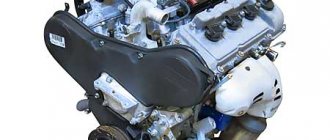
Electromechanical transmission for petrol-hybrid cars Toyota Prius and Lexus CT200h
The following requirements apply to vehicle transmissions:
- ensuring high traction qualities and speed of the machine during straight-line movement and turning;
- simplicity and ease of control, eliminating rapid driver fatigue;
- high reliability of operation over a long period of operation;
- small weight and overall dimensions of the units;
- simplicity (manufacturability) in production, ease of maintenance during operation and repair;
- high efficiency;
- in high-end cars, the requirement of noiselessness is added.
Transmission classification
By the method of transmitting and transforming the moment
transmissions are divided into
mechanical
,
hydromechanical
and
electromechanical
.
Mechanical transmissions
Mechanical transmissions - (simple and planetary) gearboxes contain only gear and friction devices. Their advantages include a high coefficient of efficiency (efficiency), compactness and low weight, operational reliability, and relative ease of production and operation. The disadvantage of a manual transmission is the stepwise change in gear ratios, which reduces the use of engine power. Taking a long time to change gears with a lever makes it difficult to control the car. Therefore, sports cars equipped with a manual transmission are equipped with electronic gear shifters (steering wheel paddles, steering wheel buttons, etc.) and gearboxes with ultra-fast synchronizing servomechanisms.
The use of mechanical transmissions is typical for Soviet tank building (simple mechanical - T-55, T-62; planetary with hydraulic servo control - T-64, T-72, T-80).
Hydromechanical transmissions
Hydromechanical transmissions have a hydromechanical gearbox, which includes a hydrodynamic torque converter (torque converter, complex hydraulic transmission) and a mechanical gearbox. The advantages of these transmissions are the automatic change of torque depending on external resistances, the possibility of automating gear shifts and facilitating control, filtering torsional vibrations and reducing peak loads acting on transmission units and the engine, and thereby increasing the reliability and durability of the piston engine and transmission .
The main disadvantage of these transmissions is the relatively low efficiency due to the low efficiency of the torque converter. With a hydraulic transmission efficiency of at least 0.8, the torque range is no more than three, which forces you to have a mechanical gearbox for three to five gears, including reverse gear. It is necessary to have a special cooling and feeding system for the hydraulic unit, which increases the dimensions of the engine and transmission compartment. Without special autologs or clutches, engine braking and launch from a tug are not provided.
Hydromechanical transmissions have become widespread in Western tank construction - M1 Abrams (USA), Leopard 2 (Germany). The transmissions of these tanks use not only hydrodynamic transmissions in the main drive, but also hydrostatic (hydrostatic) transmissions in the additional drive for turning. Of the railway equipment operating in the post-Soviet space, for example, a Hungarian-made diesel train has a hydromechanical transmission.
Hydraulic transmissions
In transport technology, hydraulic transmissions are called transmissions where switching is performed not mechanically, but by hydraulic devices, since purely hydraulic transmissions are very rare. In such a transmission there is a gearbox with primary and secondary shafts and several pairs of gears, as in a conventional gearbox, but the activation of the required pair is not carried out by a cam or friction clutch, but by a fluid coupling or torque converter, which is filled to engage the gear. The advantage of such a transmission is completely shock-free gear shifting and the absence of mechanical couplings that work unreliably when transmitting large torques (for example, on diesel locomotives); the disadvantage is the need to install a separate fluid coupling (a very cumbersome device) for each gear.
Due to the listed features, hydraulic transmission is used mainly in railway equipment. Among the domestic types of equipment, hydraulic transmission is used, for example, by shunting diesel locomotives TGM4 and TGM6, diesel train DR1.
Hydrostatic transmissions
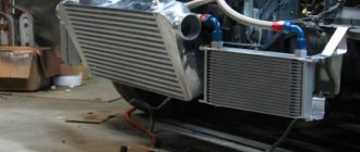
Hydraulic machine with an inclined transmission block for an asphalt roller.
In a hydrostatic (hydrostatic) transmission, axial plunger hydraulic machines are used to transmit power. The advantages of such a transmission are the small dimensions of the machines, low weight and the absence of a mechanical connection between the driving and driven transmission links, which allows them to be spaced over considerable distances and given a large number of degrees of freedom. The disadvantage of hydraulic displacement transmission is significant pressure in the hydraulic line and high requirements for the purity of the working fluid.
Hydrostatic transmission is used on road-building machines (especially rollers - due to the need to provide a very large gear ratio, and also often drive the rollers from the end, the construction of a mechanical transmission is difficult), as an auxiliary one - on diesel locomotives, aviation equipment (due to its low weight and the ability place the motor far from the pump), metal-cutting machines.
Electromechanical transmissions
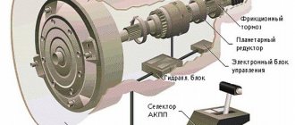
Electromechanical transmission
consists of an electric generator, a traction motor (or several), an electrical control system, and connecting cables. The main advantage of electromechanical transmissions is the provision of the widest range of automatic changes in torque and traction force, as well as the absence of a rigid kinematic connection between electric transmission units, which allows the creation of various layout schemes.
The disadvantages that prevent the widespread use of electric transmissions are the relatively large dimensions, weight and cost (especially if DC electric machines are used), and reduced efficiency (compared to purely mechanical ones). However, with the development of the electrical industry and the widespread spread of asynchronous, synchronous, valve, inductor and other types of electric drive, new opportunities are opening up for electromechanical transmissions.
Such transmissions are used in diesel locomotives, mining dump trucks, some sea vessels, tractors, self-propelled mechanisms, military equipment - on EKV tanks (USSR) and German military vehicles "Ferdinand" and "Mouse"), buses (which with this type of transmission are more correctly called thermoelectric buses , for example ZIS-154).
What is a hydromechanical gearbox: operating principle video
One of the elements of the vehicle control system is a hydromechanical transmission. Thanks to it, the driver can change gears smoothly and without jerking. Hydromechanical gearbox - what is it? Let's figure it out.
Hydromechanical gearbox
The role of automatic transmission with hydromechanical control
For a car and similar vehicles, the transmission is the unit that transmits torque from the engines to the wheels. This is how it looks in cars with a clutch, but they are gradually being pushed out of the automatic transmission market. “Automatic machines” are installed more and more often today. They do not have a clutch, and gears change automatically. Fluid mechanics help make changing gears easier while driving. In classic gearboxes, the following processes are performed when driving a car:
- disconnecting the transmission from the engine at the time of gear changes;
- when road conditions change, the amount of torque changes.
The torque converter housing rotates together with the pump wheel. The turbine is not connected to the housing (except for the period of GT blocking) - it is connected to the box shaft. In this case, the reactor is secured through an overrunning clutch - it prevents it from turning under the pressure of the flow when the difference in the speed of rotation of the pump and turbine wheels is large, but allows it to rotate with them in the same direction when the car moves at a constant speed and slippage of the GT is minimal. This way it is possible to increase the efficiency of the box.
To perform these actions, a hydromechanical automatic transmission is required. It simultaneously performs the functions of clutch and transmission. This box was specially designed for use in urban environments, where constantly squeezing the clutch can be problematic due to frequent stops in traffic jams. A car with hydromechanics is controlled using the brake and gas pedals.
Types of fluid mechanics
This transmission necessarily includes a torque converter, control system components and a manual gearbox. It can be one of several systems:
- multi-shaft;
- two-shaft;
- three-shaft;
- planetary.
The last type of box is the most common. It is often installed on passenger cars, as it does not have high metal consumption. It is characterized by less noise during operation, long service life and compactness.
Shaft mechanisms can be found on trucks and buses. To change gears, they have multi-disc clutches that are placed in oil. First gear and reverse gear are engaged using a gear clutch. Thanks to the special design of the shaft boxes, gear shifting occurs due to the operation of the crankshaft. In this case, the speed of movement is not reduced, torque and power are not interrupted.
Removing scratches on a car body without painting.
DON'T WASTE MONEY ON REPAINTING! Now you can remove any scratch from the body of your car in just 5 seconds.
Read more >>
Main purpose of automatic transmission
Torque converter functions
The torque converter performs clutch functions in modern automatic transmissions. Thanks to this unit, the car moves smoothly, without jerking. At the same time, dynamic loads are reduced, which helps to operate the engine in a gentle mode, increasing its durability. When using a torque converter, transmission parts last much longer. Due to the reduced number of gears, the driver is less tired. Torque converters are recommended for use on SUVs, since with their help you can increase the vehicle's cross-country ability in difficult conditions - in snow or sand.
Important! In Russia, it is also worth choosing transmissions with this unit, since in winter, special equipment often does not have time to clear the roads. Thanks to the torque converter, a stable traction force is created with a low rotation speed of the drive wheels, which increases their grip on the road surface.
Torque converter
Torque converter device
The torque converter is placed between the engine and the mechanical part of the box. It consists of interconnected disks with blades. The first is the pump wheel, which is the drive wheel. It connects the motor and the transformer. The turbine is driven, it is in contact with the primary shaft. The reactor is responsible for increasing the torque. The turbines are practically drowned in oil (three-quarters immersed in it).
They are covered by a housing that protects against foreign particles getting into the oil. During turbine operation, the engine torque is directed to the pump disc. At the same time, an oil flow is directed to the turbine disk under pressure. It is spun by a reactor wheel located in the central part. The resulting force is transferred to the gearbox shaft.
The torque converter operates due to a special circulation of oil, which enters it from the outer part of the pump disk, then moves to the turbine wheel and returns through the central part of this unit. The oil circulation cycle on the pump disc is completed. The torque in the torque converter is replaced automatically as the engine load increases.
This unit sends torque to the box, where the gears are engaged using clutches. The required gear ratio is determined automatically by the transformer; depending on its value, the pressure of the circulating oil changes.
Automatic transmission torque converter in section
Planetary mechanism
In most modern automatic transmissions, the torque converter operates in tandem with a planetary system. It is responsible for transmitting torque to friction clutches. In the simplest version, the force is directed to the central gear (sun gear). Two additional satellites (auxiliary gears) are in constant mesh with the central gear thanks to the teeth applied to these elements. The satellites are not fixed, but rotate freely around their axes.
The gear mechanism is located inside the crown wheel, which, depending on the gear engaged, is fixed or begins to move. At the moment the ring gear is fixed, the driven shaft begins to move (force is transmitted to it). Otherwise, the satellites transmit torque to the ring gear, leaving the driven shaft stationary. To change gears, planetary automatic transmissions are equipped with friction clutches. Each of them looks like several disks, which are thin plates of smooth metal.
Each plate is coated with a special friction compound that prevents wear. On some of them you can find slots. Gaskets are located between the couplings. They are pressed against each other using a hydraulic piston that operates by supplying working fluid. As the pressure in it increases, the clutches close tightly, becoming almost a single whole. After the fluid pressure in the hydraulic piston drops, the friction discs return to their place using a spring. The operation of friction clutches is closely related to the functioning of brake and planetary mechanisms.
Design and operation of an automatic gearbox (automatic transmission)
An automatic transmission (or automatic gearbox) changes gears independently depending on the vehicle's speed and provides the driver with a pleasant and comfortable driving experience. The driver is only required to manually select the direction of movement of the car: forward or backward.
Separately, there is a robotic transmission, where clutch release and gear shifting also occur automatically, but there is no smooth gear shift mechanism - a torque converter. Often, such a transmission is a conventional manual gearbox with a disc clutch, but all actions are performed by servos, as a result, the driver does not need to perform complex manipulations with the gearbox lever and operate the clutch in a coordinated manner. Such a transmission is called a sequential gearbox and can have automatic and manual modes (in a manual mode, the driver simply presses the gear lever to the “-” or “+” position, up or down a gear). For example, on BMW cars such a transmission is called SMG - sequential manual gearbox, sequential manual gearbox.
Friction torus variator
So far, the variator is considered the most effective (from the point of view of a smooth change in the reduction ratio). But using a rubber belt in it is only possible with low-power units (for example, scooters). Audi has developed a CVT with a metal belt in the form of a multi-row chain. However, due to the high cost, the transmission of such a passenger car turned out to be uncompetitive, and a variator of a different design is usually used - the driving and driven disks have streams of a spherical profile at the ends (when both disks are added, they form a torus), along which rubber-coated rollers are rolled, the axes of rotation of which pass through the axis of rotation of the disks, but can tilt, either becoming perpendicular to the axis of rotation of the disks, or deviate in one direction or another. This is a toroid variator.
If the axes of the disks and rollers are perpendicular, then the roller rolls along the grooves of both disks along paths equidistant from the axis on both disks, that is, it passes the same paths on both disks - the variator works as a direct transmission. If you tilt the axes of rotation of the rollers so that the point of intersection of the axes goes towards the driven disk, then along the leading stream the rollers will run along a smaller radius, and along the driven stream - along a larger one, and since the paths they take are the same on both disks, then one the driver's revolution will be less than one revolution of the slave's - the gear will be downshifted. If you tilt the axles in the opposite direction, the gear will become overdrive.
The torque converter (GT) (or torque converter in foreign sources) serves to transmit torque directly from the engine to the elements of the automatic transmission and consists of the following main parts:
- pump wheel or pump;
- torque converter lock-up plate (lock-up piston);
- turbine wheel or turbine;
- stator;
- overrunning clutch (one-way clutch).
The torque converter operates on the principle of transmitting motion through a layer of liquid. The degree of connection between the pump wheel and the turbine wheel can be smoothly changed. Automation does this. The disadvantage of such a device is the large losses due to fluid mixing (low efficiency), which does not make it possible to use it directly as the main gearbox, but only as a liquid clutch.
Hydromechanical gearboxes
The main inconvenience when using manual manual transmissions is that the driver constantly has to press the clutch pedal and move the gear lever to change gears. This requires significant physical effort from him, especially in city traffic or when driving a car that operates with frequent stops.
, hydromechanical gearboxes are becoming increasingly used . They perform simultaneously the functions of a clutch and a gearbox with automatic or semi-automatic gear shifting.
With a hydromechanical transmission, the vehicle's movement is controlled by the fuel pedal and, if necessary, the brake pedal.
The hydromechanical gearbox consists of a torque converter and a manual gearbox. In this case, a manual transmission can be two-, three- or multi-shaft, as well as planetary.
Hydromechanical shaft-mounted manual transmissions are used mainly on trucks and buses. To change gears in such boxes, multi-disc clutches (clutches) operating in oil are used, and sometimes, to engage low gear and reverse gear, a gear clutch is used. Gear shifting using clutches occurs without reducing the speed of rotation of the engine crankshaft, i.e. stepless – without interruption in transmitted power and torque.
Hydromechanical gearboxes with planetary manual gearboxes are most widespread and are used in cars, trucks and buses.
Their advantages : compact design, lower metal consumption and noise, longer service life.
Disadvantages include design complexity, high cost, and reduced efficiency.
Gear shifting in these boxes is carried out using friction clutches and band brake mechanisms. At the same time, when one gear is engaged, some of the friction clutches and band brake mechanisms slip, which also reduces their efficiency.
Torque converter
The torque converter (Figure 1) is a hydraulic mechanism that is located between the engine and manual transmission. It consists of three wheels with blades - a pump (driver), a turbine (slave) and a reactor.
The pump wheel 3 is mounted on the flywheel 1 of the engine and forms a torque converter housing, inside of which there is a turbine wheel 2 connected to the input shaft 5 of the gearbox, and a reactor 4 mounted on the freewheel roller clutch 6.
The internal cavity of the torque converter is filled with 3/4 of its volume with a special low-viscosity oil.
Figure 1 – Torque converter
a – general view; b – diagram; 1 – flywheel; 2 – turbine wheel; 3 – pump wheel; 4 – reactor; 5 – shaft; 6 – coupling
When the engine is running, the pump wheel rotates with the engine flywheel. The oil, under the influence of centrifugal force, flows to the outer part of the pump wheel, acts on the blades of the turbine wheel and causes it to rotate. From the turbine wheel, the oil flows into the reactor, which ensures a smooth and shock-free entry of the liquid into the pump wheel and a significant increase in torque. Thus, the oil circulates in a closed circle, ensuring the transmission of torque in the torque converter.
A characteristic feature of the torque converter is an increase in torque when it is transmitted from the engine to the input shaft of the gearbox. The greatest increase in torque on the turbine wheel of the torque converter is obtained when the car starts moving. In this case, the reactor is motionless, as it is braked by the freewheel.
As the vehicle accelerates, the rotation speeds of the pump and turbine wheels increase. In this case, the freewheel wedges, and the reactor begins to rotate at an increasing speed, having less and less influence on the transmitted torque. After the reactor reaches its maximum rotation speed, the torque converter stops changing torque and switches to the fluid coupling operating mode .
This results in smooth acceleration of the car and a stepless change in torque.
The torque converter automatically sets the required gear ratio between the engine crankshaft and the vehicle's drive wheels. This is ensured as follows: with a decrease in the speed of rotation of the driving wheels of the car and an increase in movement resistance, the dynamic pressure of the fluid from the pump to the turbine increases, which leads to an increase in torque on the turbine and, consequently, on the drive wheels of the car.
Planetary gearbox
A planetary gearbox includes planetary gears. In the simplest planetary mechanism (Figure 2), the sun gear 6, mounted on the drive shaft 1, is meshed with the satellite gears 3, freely mounted on their axes. The axes of the satellites are mounted on a carrier 4, rigidly connected to the driven shaft 5, and the satellites themselves are meshed with a ring gear 2, which has internal teeth.
Figure 2 – Planetary mechanism
1 – drive shaft; 2 – ring gear; 3 – satellites; 4 – carrier; 5 – driven shaft; 6 – sun gear; 7 – brake
The transmission of torque from the drive shaft 1 to the driven shaft 5 is possible only when the ring gear 2 is braked using a band brake 7. In this case, when the gear 6 rotates, the satellites 3, rolling along the teeth of the stationary gear 2, will begin to rotate around their axes and at the same time through the carrier 4 will rotate driven shaft 5. When gear 2 is released, satellites 3, freely rolling over gear 6, will rotate gear 2, and shaft 5 will remain stationary.
Figure 3 shows a diagram of a hydromechanical gearbox , which consists of a torque converter, a three-shaft two-stage manual gearbox and a control system. The presence of a two-speed manual transmission increases the torque control range.
Figure 3 – Diagram of a hydromechanical gearbox
1, 6, 7, 9, 10, 11, 13 – gears; 2, 3, 17 – clutches; 4 – coupling; 5, 12, 19 – driven, intermediate and drive shafts; 8 – regulator; 14, 15 – pumps; 16 – crankshaft; 18 – torque converter
The hydromechanical gearbox includes a drive 19, driven 5 and intermediate 12 shafts with gears, multi-disc friction clutches 2, 3, 17 (clutches) and a gear coupling 4 with a drive. The control system includes front 15 and rear 14 hydraulic pumps and a centrifugal regulator 8, which acts on clutches 2, 3, 17, which ensure gear shifting.
In the neutral position, all clutches are turned off, and when the engine is running, no torque is transmitted to the secondary shaft 5. In 1st (downshift) gear, the control system automatically engages clutch 2.
In this case, the drive gear 1, freely mounted on the drive shaft 19 of the gearbox, is blocked by the shaft, and the gear coupling 4 is manually set to the forward position using a remote control system.
Torque in first gear from the torque converter is transmitted through clutch 2, gears 1, 13, 11, 10 and gear coupling 4 to driven shaft 5 of the gearbox.
When accelerating in 1st gear, when the torque converter automatically carries out a given range of torque control, the speed increases to the optimal value for switching to 2nd gear. In this case, centrifugal regulator 8 gives a signal to turn on clutch 3 and turn off clutch 2.
Transmission Maintenance
Main symptoms of a malfunction:
- slipping;
- incomplete shutdown;
- jerking while moving from a standstill;
- noise in the clutch while driving;
- pedal sticking;
- leakage of fluid in the clutch drive connections.
Clutch slipping can occur due to:
- limited pedal free travel due to improper adjustment or wear of the friction linings;
- wear of the friction linings of the driven disk.
In this case, the torque from the engine is not fully transmitted, the car’s acceleration deteriorates, the starting point slows down, and in the event of a lot of slipping, the car remains motionless, even if the gear is engaged and the clutch pedal is released.
To eliminate the malfunction, you need to check the free play in the center of the pedal platform: it should be 35-45 mm on Moskvich cars, 26-38 mm on ZAZ cars, 26-35 mm on VAZ cars and 12-28 mm on GAZ cars. 24. Free play is created primarily due to the gap between the clutch release fork and the release bearing pressure clutch, that is, it is identical to the movement of the pedal until the diaphragm spring begins to deflect (on VAZ and Moskvich vehicles) or until the coil springs begin to compress (ZAZ, GAZ-24, VAZ).