MY MOTORCYCLE
High taxes on engine displacement and strict environmental standards are forcing manufacturers to grapple with a difficult problem: how to create a powerful internal combustion engine with a relatively small displacement. The VTEC system is one of the ways to create a low-volume, powerful engine. A well-known fact: in a four-stroke engine, the camshaft is responsible for controlling the valves. Specially formed cams on the camshaft are responsible for the opening moments of the intake and exhaust valves. The opening height of the valves and the time for which the valve opens ensure that the cylinders are filled with fresh working mixture and ventilation when exhaust gases are released. All these parameters are completely dependent on the cam profile. Due to the different behavior of gas mixtures in the cylinders at different engine speeds, different valve settings are required. Thus, optimal settings for the opening moment, stroke and duration of valve opening at low speeds will result in insufficient filling of the cylinders with the working mixture at high speeds, leading to unstable engine operation and loss of power. Thus, for each engine operating mode it is necessary to have its own optimal camshaft with certain valve opening moments and cam profiles.
Principle of operation
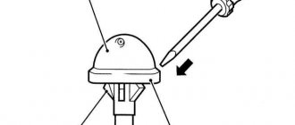
Diagram of the operation of the Hyper VTEC system used on the Honda VFR800 model. The first illustration shows the operation of part of the timing system at low and medium speeds: the rotating camshaft does not open the valve. When the engine speed reaches about 7000, oil pressure moves a tiny pin, taking the load from the camshaft lobe to the valve. Voila - the valve opens!
The essence of the VTEC system is the combination of several cam profiles on one camshaft. Thus, the valves can open to different heights and for different times. In addition, the timing of the valve opening may also vary. The operation of the system is controlled taking into account oil pressure, oil temperature, coolant temperature and engine speed. The functions of analyzing data and issuing the necessary control commands are performed by a special electronic device. As a result, we get an engine that is capable of changing and finding optimal gas distribution settings, adapting to the operating mode. Physically, the mechanism for turning the valves on and off is quite simple. Everything is based on oil pressure, which is controlled electronically. Oil is supplied from the oil pump to branches independent of the main line. The branches run in the engine head parallel to the camshafts. The valves turn on when there is sufficient pressure in the channels supplying oil to them. Accordingly, when the pressure drops, the valves turn off. The presence and absence of pressure is created by shut-off valves at the ends of the oil supply branches, since the oil pump produces generally constant pressure in all modes of engine operation. The shut-off valves are electronically controlled. The mechanism that directly connects the valve is very similar to the hydraulic compensator common in modern engines. Until the oil and coolant temperatures reach the optimal temperature, the electronics do not give a command to close the shut-off valves, regardless of engine speed.
Where is it used?
Since 2002, the VTEC system has been used in the VFR800 engine
The VTEC system was first used by Honda on the Civic CRX SiR in 1989. This provided the 1.6-liter engine with an impressive power of 157 hp. The use of VTEC on motorcycles led to the emergence of a new generation of the system - VTEC-E. It is designed not only to increase engine performance at high speeds, but also to improve efficiency at low speeds. An example of the use of VTEC is the domestic Japanese model CB400 Super Four Hyper VTEC, released in 1999. The four-cylinder engine of this motorcycle with four valves per cylinder operates using only two valves at low speeds. That is, the engine itself limits the amount of working mixture and ventilation of the cylinders, thereby saving fuel. As the speed and oil pressure increase, another pair of valves are connected - as a result, the engine's power and efficiency increase. Despite the high popularity of the SV400 Super Four in Ukraine, Hyper VTEC models rarely reach us. Since 2002, a similar system has been used on the VFR800 motorcycle with a V4 engine, two camshafts in the cylinder heads and four valves per cylinder.
Source BIKE magazine No. 5/2007
Design of the DOHC i-VTEC (VTEC) system from Honda
DOHC i-VTEC is the pinnacle of technology Honda has applied to road cars today. The Civic Type R, Civic Si, RSX Type S, Accord Euro-R, S2000 are all linked by a red heart called DOHC i-VTEC.
DOHC i-VTEC is an engine valve control system. And in order to begin to explain the very essence of the system, it would not be amiss to remember what gas distribution is and its main components.
Gas distribution is nothing more than the process of admitting a fresh charge of the fuel-air mixture into the engine cylinders and releasing exhaust gases. Power and torque, fuel consumption and exhaust toxicity directly depend on the efficiency of gas distribution, i.e. how efficiently the cylinders are filled with fresh fuel and how effectively the combustion products are removed.
Honda engine with DOHC i-VTEC
If you dig deeper, it turns out that the camshaft cams have a direct influence on the gas distribution process. Or rather, their profile, height and angular position of the intake cams relative to the exhaust cams.
If it were possible to create cams with a profile and angle that provided the best power, economy and emissions characteristics across the entire engine speed range, the advent of systems such as VTEC would be inexplicable. Of course, it is impossible to create such cams, which is why VTEC exists.
During operation at high speeds, the time during which the valves are open is reduced. In order to achieve optimal filling of the cylinder with the fuel-air mixture, and after combustion to get rid of exhaust gases, the valves must open earlier and close later, thereby increasing the “open” time of the valves. It is very easy to select the appropriate profile for the cams, but at low speeds you will have to pay for such a gas distribution. Through a prematurely opened exhaust valve, exhaust gases will enter the exhaust tract from the cylinder, which still have energy that has not been spent on useful work, i.e. unburnt fuel.
Due to the late closing of the same exhaust valve, some of the fresh combustible mixture may then enter the exhaust manifold before ignition. Another part of the fresh charge may also be “overboard” through the inlet valve that failed to close. This portion of the air/fuel mixture will flow back into the intake manifold. It is clear that such engine operation is far from efficient, and losses in both fuel consumption and power are obvious.
DOHC i-VTEC allows you to avoid the troubles described above at low speeds and provide significant returns at the “top” and mid-range speeds. In principle, the previous generation DOHC VTEC handled this quite well, but the DOHC i-VTEC has more low-end traction than the old DOHC VTEC cannot boast of. This may not be the only difference between the old and new twin-shaft VTEC. Unfortunately, I haven’t driven the red-headed DOHC i-VTEC, so I simply have no right to make further comparisons. I am sure that each of them will have its pros and cons. However, the new DOHC i-VTEC is more productive and this fact is worth recognizing.
During the long introduction, you probably thought that the DOHC i-VTEC system has no variations. However, Honda itself positions it without division, although in fact DOHC i-VTEC has two subtypes that take their roots from the previous generation VTEC.
Varieties of DOHC i-VTEC
DOHC i-VTEC DOHC VTEC + VTC
DOHC i-VTEC I SOHC VTEC-E + VTC + non-Vtec exhaust camshaft
| System | Type VTEC | VTC |
| DOHC i-VTEC | VTEC on intake and exhaust. VTEC response torque is 5800 rpm. | on the intake camshaft |
| DOHC i-VTEC I | VTEC-E on the intake, standard exhaust camshaft. VTEC response torque is 2500 rpm. | on the intake camshaft |
By and large, the prefix “i” in system names implies that VTC works in conjunction with the VTEC system. But before we figure out what VTC is, let’s remember the operating principle of traditional VTEC and VTEC-E, since DOHC i-VTEC in both of its manifestations is based precisely on the operating principles of the first generation VTEC.
DOHC i-VTEC
Recall that in a standard engine, each valve in the cylinder has its own cam on the camshaft. However, in engines with DOHC i-VTEC, there are 3 cams on the camshaft for every two valves - two standard outer cams and one central cam with a more aggressive profile, which comes into operation from the moment the VTEC system is turned on. That is, the operating principle of the new DOHC VTEC (part of the DOHC i-VTEC) is absolutely identical to the operation of the first generation DOHC VTEC
The design and principle of operation of VTEC as a component of the DOHC i-VTEC system
Two outer cams are responsible for operating the engine at low speeds, and the central one is connected at high speeds. Please note that the cams do not act on the valves directly, but through the so-called rocker arms/rockers, of which there are also three for two valves.
While the VTEC system is resting, each rocker operates independently of each other. External cams ensure the opening of the valves, and the central cam, although it rotates along with the others, for the time being works at idle. As soon as the engine reaches high speed mode, the VTEC system turns on (5800 rpm). Using oil pressure, the system moves special pistons (synchronizing pin) inside the rockers so that all three rockers become one single structure. The previously idling central cam comes into play. Now the two outer rockers begin to work according to the laws of the central cam, driving the valves deeper.
Thus, in VTEC mode, more fuel-air mixture enters the cylinders, and as a result, a significant increase in power.
DOHC i-VTEC I
VTEC-E, a component of the DOHC i-VTEC I system, works a little differently. If DOHC i-VTEC is configured for maximum performance, then the main task for DOHC i-VTEC I is fuel economy with “decent traction.”
The design and principle of operation of VTEC in DOHC i-VTEC I
The essence of the system is that at low speeds the engine runs on a lean fuel-air mixture, which enters its cylinders only through one intake valve. Yes, yes - exactly one, thereby turning the 16-valve 4-cylinder engine into a 12-valve one. If the DOHC i-VTEC uses an additional third cam, then in the case of the DOHC i-VTEC I one of the two cams is simply disabled at low speeds. Entering the cylinder through only one valve, the working mixture begins to swirl intensely, making combustion more efficient and stable. When the speed increases (2500 rpm and above), the VTEC system is activated and only then do both valves begin to work together.
The operating principle of DOHC i-VTEC I is exactly the same as that of the first generation VTEC-E. The only difference is that the DOHC i-VTEC I has two camshafts - an intake with VTEC-E and a standard exhaust.
VTC
VTC is that additional component that turns DOHC VTEC into the new “DOHC i-VTEC” and “VTEC-E” into “DOHC i-VTEC I”. This is a mechanism that rotates the intake camshaft relative to the exhaust camshaft using oil pressure.
The abbreviation VTC stands for Variable Timing Control, which translated means “Variable Valve Timing System”. In fact, the decoding of the name has the same meaning as VTEC. In principle, the goal of these systems is the same, but each does it differently and at the same time complements each other. An additional VTC system is installed and only affects the intake camshaft.
At high speeds, the time for opening and closing the valves is much less, although more fuel-air mixture needs to be supplied. Therefore, it is necessary to increase the opening phase and valve lift height, which is what VTEC does, and the VTC system “creates favorable conditions” for the effective operation of VTEC.
If the VTEC system, with the help of an additional cam, allows you to drive the valves deeper and slightly increases the open time, then VTC makes it possible to tighten the camshaft so that the valves open earlier, which contributes to more efficient ventilation of the cylinders. Unlike the main VTEC system, which is activated at a certain speed range, the additional VTC system operates constantly and continuously, adjusting the opening timing of the intake valves depending on the engine load. Let's figure out how she does it.
Working mechanism of VTC
The actuator of the VTC system is integrated into the intake camshaft pulley. If a regular pulley is a one-piece structure, one piece of metal, then a VTC pulley consists of several parts.
One of the parts is the VTC pulley housing, which is rigidly attached by the timing chain to the exhaust and crankshaft pulleys. The other part is the VTC pulley blade - a part that has free movement inside the VTC pulley and is rigidly attached to the intake camshaft. The cavity inside the VTC pulley housing, in which the blade has free movement, is filled with engine oil. The oil supply to the pulley cavity is organized on both sides of the blade. Thus, by applying oil pressure to one side, we rotate the blade in the other direction. And by acting on the VTC pulley blade, we directly influence the camshaft with cams and, as a result, change the angle of the intake cams relative to the exhaust cams.
The role of the controller in this process is played by the VTC solenoid. Receiving data about the load on the engine from the ECU, the solenoid directs oil pressure to one side.
How does this happen. The VTC solenoid is supplied with engine oil, which has a certain system pressure, which is transmitted to the VTC solenoid. Inside the solenoid, the oil direction is divided into two channels - let's call them the red channel and the yellow channel. Both of these passages lead from the solenoid to the VTC pulley cavity, in which the VTC pulley blade is free to move. The red channel is connected to one side of the pulley blade, and the yellow channel is connected to the other.
The overlap angle (valve overlap) is the angle of position of the intake valves relative to the exhaust valves at which the intake and exhaust valves are open simultaneously. Simply put, it is the point in time when the intake and exhaust valves are open at the same time.
Depending on engine operating conditions, the solenoid directs oil pressure to either the red or yellow channel. And if the pressure is directed, for example, into the red channel, then the yellow channel drains - acting on the pulley blade on one side, the system forces the blade to squeeze out oil on the other side.
At idle and at low speeds with light engine load, the VTC system reduces the valve overlap angle to a minimum to keep the engine running smoothly. As the load increases, the system smoothly increases the overlap angle. At high speeds and under heavy load, the system turns the camshaft (increases the overlap angle) to the maximum possible level. The valve overlap angle depends on the engine model and is usually in the range of 25 - 50 degrees.
* * *
Without going into the details of the design of engines with DOHC i-VTEC, we can say that the essence of the topic is revealed in this article. In fact, the new DOHC i-VTEC in both its forms is the good old VTEC supplemented with the new intelligent VTC feature. And it is precisely due to VTC that engines with DOHC i-VTEC (both subtypes) began to work much more elastically than engines with first-generation VTEC and have more traction at the bottom.
Undoubtedly, the new engines are more productive, more technologically advanced and better, but the new VTEC has lost something - due to the acquired qualities, the inclusion of VTEC, which “drives” and “turns in” so much.
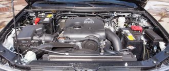
Honda Odyssey 2005, petrol engine 2.4 l., 160 l. p., front wheel drive, CVT — scheduled maintenance
This is what that same filter looks like. The mesh turned out to be perfectly clean. But the rubber was oak.
Couldn't maintain integrity when gouging out. However, this system is controlled electrically by the ECM engine control unit through a valve, which, upon command from the control unit, opens or closes the oil supply to the channel of the VTEC system. This is the valve we will talk about.
Then the troubles begin, which do not always end in one day and are almost always associated with spending extra money. Of course, nothing can be done for free, but often, due to ignorance of money, more is spent than necessary. As mentioned above, the valve is needed to control the oil supply to the channel of the VTEC system, everything is simple: Well, first of all, according to sensor readings, the pressure in the intake manifold, air flow, and mixture composition should change.
But Honda engineers took a simpler path - they installed a pressure sensor at the valve outlet. If the valve is turned on and the sensor shows that there is no pressure, or vice versa, the valve is turned off and the sensor shows the presence of pressure, then the ECM detects a malfunction, lights up the “check engine” malfunction indicator on the dashboard and writes a fault code into memory: On machines from the year of manufacture The P code has been replaced by two other codes that not only indicate a system malfunction, but also indicate: If the resistance is ohms, check the wiring between the VTEC solenoid valve and terminal A8 of the electronic control unit.
Connect the VTEC solenoid valve connector.
Remove the M10 bolt and install the special tools as shown. If the pressure is above 49 kPa 0.
Disconnect the VTEC valve connector. If the pressure is higher than kPa 4. If the fault disappears, replace the ECM. Remove the VTEC solenoid valve assembly from the cylinder head and check to see if the solenoid valve filter is clogged. If the filter is not clogged, press the VTEC solenoid valve with your finger and check its movement.
Valve (solenoid) VTEC VTEC solenoid part3
Set the piston of the first cylinder to TDC. Remove the ignition wire cover and wires.
Tags: generator, kW, Honda, price
- Related Posts
- HONDA CENTER (HONDA CENTER) in Karaganda
- Official dealer of Land Rover (Land Rover) in Krasnodar - KLYUCHAVTO
- Honda Civic: history, photo, review, characteristics of Honda Civic on diabloarea.ru
« Previous entry
Good day! Some time ago I had a question about buying the first motorcycle in my life and it so happened that my choice fell on the HONDA CB400. And since I had no experience at all, and there are a lot of stories about what rickety Pepelats are found in the vastness of our great Motherland, I decided to properly read the manual and find out how to choose a really good motorcycle and not be deceived in our not so easy crisis period. While studying the history of HONDA construction, I came across the mysterious HONDA CB400SFVK motorcycle. When I was trying to understand what the educational version of CB 400 is and how it fundamentally differs from the full version, I searched through a bunch of sites and found a lot of information, here I will try to put it together and provide it in a “for beginners” format, which I so lacked.
The HONDA CB400SFVK has been produced since approximately 1999-2000 (it was not possible to find exact data), that is, approximately since the birth of the VTEC versions of the “Sibishka”. This version is educational and is intended for training novice motorcyclists in Japan. In Japan, because in our country they teach on the full version... you understand, only youth, only hardcore. The main differences from the regular CB 400 are a much more affordable price tag, the engine is “strangled” from 53 to 35 hp. and the maximum speed limit is 150 km/h, some owners actually claim that the motorcycle easily runs at 180.
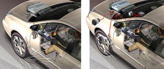
Note: in order not to get confused, please note that in the photographs presented, the educational version is ALWAYS on the left, and the full version is ALWAYS on the right. As an example of a training version, I took a 2005 HONDA CB400SFVK.
Go!
Steering wheel If you have previously driven a SV400, you will easily understand what is wrong. The thing is that on the training version the steering wheel is slightly raised. What to do if there was no opportunity to sit? In principle, this sign is not so obvious and is listed here rather “for show”, but at least this should be another proof for you that you should not thoughtlessly take the first motorcycle you come across, try to look at at least 3-4 options before buying and sit on each.
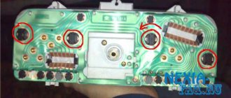
Dashboard Without getting into details, the most obvious sign is the noticeably larger sizes of the “glasses” (marked in blue) on the training version, the absence of beauties, such as iron inserts in the dashboard body, a slightly different arrangement of indicators and, of course, the absence of a display.
The headlight glass on the training version has a convex shape, while on the full version it is flat. The headlight housing itself is also different; on the full-fledged version, the headlight is inserted into the body and has a “groove” along the edges, but on the training headlight, the headlight is of the old design and looks monolithic. Speaking about the case, it is also worth noting that in the educational version it is completely black. In the original, the motorcycle is still hung with a “festive” garland from which kilometers of wires stretch, but in real life they will all be dismantled.
Mounting for arches For obvious reasons, the training version initially has more options for installing arches. The most important beacon indicating training is located in close proximity to the radiator (marked in blue), this is one of those signs that is really worth paying attention to, since it is not so easy to hide such differences.
For a better understanding, this is what the tutorial looks like with installed arches under the steering column:
Brake discs and pads The brake system exactly repeats the pre-VTEC versions of motorcycles: on the front fender there is no element “hugging” the fork, different pads are installed, slightly, but the brake discs themselves are different.
Engine cover Another “hello” from older models and one of the most obvious signs. The most important thing to remember here is that since 1999, that is, since the beginning of the production of VTEC, the cover has changed its appearance forever; a motorcycle of 1999 and older cannot have the old cover. If it happens that the owner somehow replaces the cover, it doesn’t matter. Pay attention to the window for monitoring the oil level (marked in blue and located under the engine cover); on the tutorial (as on older versions) there is a dipstick instead for measuring the oil level. For those with an especially keen eye: did you notice the moved HONDA sign?
Rear shock absorbers For obvious reasons, the simplest shock absorbers are installed, even on pre-VTEC versions they are not installed. Most likely the owner will replace them with something more decent, but it’s worth paying attention.
Radiator On full-fledged versions (including pre-VTEC) there is an iron plate.
Engine The training version does not have oil channels, just like the pre-VTEC versions of the motorcycle. This knowledge will be useful if in front of you is a motorcycle manufactured in 1999+ and you see other signs of training.
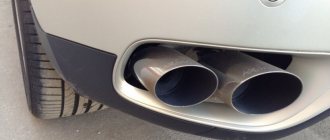
Plugs on pipes Exclusively educational “trick”
Idle air control As in the case of plugs, it is found only on training versions of the motorcycle
Stickers on the tank As a rule, there are none, but if they are, most likely the owner is not hiding the fact that this is a training version, a very simple and obvious sign.
Slot on the cover on the right, inscriptions Most stickers and covers do not survive to the future owner, if only simply because they are easy to replace, so just pay attention.
Wires When creating the motorcycle, changes were made not only to the engine, but also to the electronics. There are significantly more wires in the motorcycle than in the full-fledged version, but if you haven’t seriously read the manual and don’t know how and where the wires should be or have simply never looked under the seat, it will not be easy for you to assess the scale of the disaster. Actually, electronics is one of the sore points of training, keep this in mind if you decide to buy such a motorcycle for yourself.
Documents In general, this should always be done after, and in some cases before, inspecting the motorcycle you are interested in. Anyway, if you have any suspicions, take a look at the documents. In the documents, please note that: - in the “motorcycle name” column there should not be anything similar to “HONDA CB400SF VK ” or “Honda CB 400 SF License ” - also pay attention to the engine power, it should be 53 hp. This is also true for pre-VTEC versions. And of course, if you see an obvious training in front of you, and its power is the same as that of a full-fledged version, I recommend abandoning this purchase; at best, the service life of such an engine was seriously reduced after the intervention.
That's all.
PS This post is not intended to create a negative image of the educational version of CB400. The purpose of this post is to avoid falling into the trap of unscrupulous people who live by the principle “without a sucker, life is bad.”
VTEC system - general information and checking the condition of Honda Accord components
- Repair manuals
- Repair manual for Honda Accord 1998
- VTEC system - general information and checking the condition of components
VTEC system - general information and checking the condition of components
General information
The VTEC system was developed by Honda to provide dynamic control of valve timing and valve opening. Engines equipped with this system are marked with the inscription VTEC molded on the cylinder head cover. The corresponding engine series number (F23A1 or F23A4) is stamped on the side of the block facing the radiator.
The difference between engines equipped with a VTEC system and the basic version lies solely in the principle of valve timing control and the design features of the valve mechanism. The design of the reduced engine block kit, the organization diagram of the lubrication and cooling systems remain the same, as well as the list, design and location of the attached units.
The on-board processor of the engine management system of VTEC-equipped models is capable of adjusting the timing and degree of opening of the intake valves through the use of camshaft cams of various sizes and shapes. Depending on the data received from the information sensor, the processor either turns on or turns off the system.
The order of operation of both types of VTEC systems is determined by the following initial parameters:
a) Engine speed (rpm); b) Vehicle speed (mph); c) Throttle Position Sensor (TPS) output; d) Current engine load, determined by readings from the intake manifold absolute pressure (MAP) sensor; e) Coolant temperature.
The camshaft is equipped with three cams that drive each of the engine intake valves, differing from each other in profile shape and lift height, which determine the duration and amount of opening of the corresponding valves.
At low engine speeds, the secondary intake valves are actuated by their own camshaft cams, which have a very low lift and pointed shape (i.e., the valves open only slightly and very briefly, compared to the primary ones), keeping atomized fuel from consolidating inside the cylinder head. At the same time, good lower torque is developed with high response speed, which determines excellent traction characteristics and high throttle response of the car. In this case, the primary cams function in normal mode, creating vortices of the combustible mixture in the combustion chambers.
If there is a need to increase engine output, the secondary rocker arms are locked through intermediate ones with the primary special synchronizing pistons. The synchronizing pistons are hydraulically driven and electronically controlled. When the rocker arms are blocked, both intake valves begin to open in the same mode, and the degree and duration of their opening are determined by the shape of the intermediate rocker arm cam and are of increased importance.
| The secondary rocker arms are no longer in contact with their own cams until the system is switched off. At the same time, both valves open to their full height and for maximum duration, providing increased engine speed and performance. |
Checking the condition of components
| Inspection of some of the VTEC components requires removal of the rocker arm assembly (see Section Removal, condition check and installation of the rocker arm assembly ). |
VTEC Lockup Control Solenoid Valve
Rocker arms
| EXECUTION ORDER |
Valve clearance correctors
| EXECUTION ORDER |
| EXECUTION ORDER | ||
Synchronizing Assemblies↓ Comments ↓1. Honda Accord cars 1.0 Honda Accord cars 1.1 Controls and operating techniques 1.2. Access, protection 1.3 Vehicle identification numbers 1.4 Purchasing spare parts 1.5 Maintenance technology, tools and workplace equipment 1.6 Jacking and towing 1.8 Audio security system 1.9 Starting the engine from an auxiliary power source 2. Automotive chemicals, oils and lubricants 2.0 Automotive chemicals, oils and lubricants 2.2 Diagnosis of malfunctions of vehicle components and systems 2.3 Settings and routine maintenance 2.4 General information about settings and adjustments 2.5 Checking fluid levels 2.6 Checking the condition of tires and their inflation pressure 2.7 Checking the power steering fluid level 2.8 Checking the ATF AT level 2.9 Replacing the engine oil and oil filter 2.10 Checking the condition and replacing the wiper blades 2.11 Checking, maintaining and charging the battery 2.12 Checking the condition, adjusting the tension force and replacing the drive ones 2.13 Checking the condition and replacing the hoses located in the engine compartment 2.14 Checking the condition of the cooling system components 2.15 Rotating the wheels 2.16 Checking the brake system 2.17 Checking the condition of the seat belts 2.18 Replacing the air cleaner filter element 2.19 Checking the manual transmission oil level 2.20 Inspecting the suspension and steering components, checking the condition of the protective covers of the drive shafts 2.21 Checking the condition of the exhaust gas system components 2.22 Checking the condition of the power system components 2.23 Checking condition and replacement of spark plugs 2.24 Checking the condition and replacing the spark plug wires, cap and slider 2.25 Checking and replacing the controlled crankcase ventilation (PCV) valve 2.26 Cooling system maintenance (draining, flushing and refilling) 2.27 Replacing brake fluid 2.28 Replacing automatic transmission fluid ( AT/CVT) 2.29 Replacing manual transmission oil 2.30 Replacing air conditioning system filters 2.31 Checking and adjusting valve clearances (if necessary) 2.32 Resetting the maintenance interval indicator 2.33 Checking and adjusting idle speed 3. Engine 3.0 Engine 3.1. Four-cylinder engines 3.2. Engines V6 3.3. General and major engine repairs 4. Cooling and heating systems 4.0 Cooling and heating systems 4.1 Antifreeze - general information 4.2 Checking the proper functioning and replacing the thermostat 4.3 Checking the condition of the cooling system fans and their circuits 4.4 Removing and installing the radiator and expansion tank of the cooling system 4.5 Checking the condition of the water pump 4.6 Replacing the water pump 4.7 Checking the proper functioning and replacing the meter sensor unit 4.8 Checking the proper functioning of the drive electric motor 4.9 Removing and installing the electric motor of the heater fan drive 4.10 Removing and installing the operation control panel assembly 4.11 Removing and installing the heat exchanger of the heater 4.12 Checking the proper functioning and maintenance of heating systems 4.13 Checking the electrical circuit of the K/V compressor clutch 4.14 Removing and installing the K/V receiver-dryer 4.15 Removing and installing the K/V compressor 4.16 Removing and installing the K/V condenser 4.17 Removing and installing the K/V evaporator with expansion valve 5. Power and exhaust systems 5.0 Power and exhaust systems 5.1 Relieving pressure in the power system 5.2 Checking the proper functioning of the fuel pump, measuring the fuel pressure 5.3 Checking the condition and replacing fuel lines 5.4 Removing and installing the fuel pump 5.5 Checking the condition and replacing the sensor 5.6 Removing and installing the fuel tank 5.7 Cleaning and repair fuel tank - general information 5.8 Removing and installing the air cleaner assembly 5.9 Removing, installing and adjusting the accelerator cable 5.10 Electronic fuel injection system (EFI) - general information 5.11 Checking the proper functioning of the injection system 5.12 Removing and installing the throttle body 5.13 Removing and installing the fuel pressure regulator 5.14 Removal and installation of the fuel line and fuel injectors 5.15 Exhaust system - general information 6. Engine electrical equipment 6.0 Engine electrical equipment 6.1 General information and precautions 6.2 Starting the engine from an auxiliary power source 6.3 Checking the condition and replacing the battery 6.4 Checking the condition and replacing battery wires 6.5 Ignition system - general information 6.6 Checking the functioning of the ignition system 6.7 Checking the condition and replacing the ignition coil 6.8 Checking serviceability functioning and replacement of the control module 6.9 Removing and installing the ignition distributor 6.10 Checking the ignition timing setting 6.11 Charge system - general information and precautions 6.12 Checking the state of the charge system 6.13 Removing and installing the generator 6.14 Replacing the voltage regulator and generator brushes 6.15 Starting system - general information and precautions 6.16 Checking the functioning of the starter on the car (in 6.17 Removing and installing the starter 6.18 Removing and installing the traction relay 7. Motor control 7.0 Engine management 7.1 On-board diagnostic system (OBD) - principle of operation 7.2 Removing and installing the PCM/ECM 7.3 Checking the condition and replacing the throttle position sensor 7.4 Checking the condition and replacing the absolute pressure sensor 7.5 Checking the condition and replacing the intake temperature sensor 7.6 Checking the service condition and replacement of the cooling temperature sensor 7.7 Checking the condition and replacing the TDC/position sensor 7.8 Checking the condition and replacing the piston position sensor 7.9 Checking the condition and replacing the electrical control detector 7.10 Checking the condition and replacing the pressure switch switch 7.11 Checking the condition and replacement oxygen sensor (l-probe) 7.12 Checking the serviceability and replacing the knock sensor 7.13 Checking the serviceability and replacing the speed sensor 7.14 Checking the serviceability and replacing the stabilization valve 7.15 Checking the serviceability and replacing the air valve 7.16 Controlled crankcase ventilation system (PCV) 7.17 System Exhaust gas recirculation (EGR) - general information, 7.18 Evaporative emission control system (EVAP) - general information, 7.19 Catalytic converter - general information, condition check 8. Clutch and drive shafts 8.0 Clutch and drive shafts 8.1 Clutch - general information and checking the condition of components 8.2 Removing and installing the clutch master cylinder 8.3 Removing and installing the clutch slave cylinder 8.4 Removing air from the hydraulic path of the release drive 8.5 Removing, checking the condition and installing components of the clutch assembly 8.6 Removing, checking condition and installation of the release bearing and 8.7 Adjusting the clutch pedal 8.8 Checking the condition, replacing and adjusting the sensor switch 8.9 Removing and installing drive shafts 8.10 Removing and installing the intermediate shaft 8.11 Replacing protective covers and checking the condition of CV joints 9. Brake system 9.0 Braking system 9.1 Anti-lock brake system (ABS) - general information and codes 9.2 Replacing brake pads of disc brakes 9.3 Removing and installing disc brake calipers 9.4 Checking the condition, removing and installing a brake disc 9.5 Replacing rear wheel drum brake shoes 9.6 Removing and installation of wheel cylinders 9.7 Removing and installing the main brake cylinder 9.8 Checking the condition and replacing brake lines and hoses 9.9 Bleeding the brake system 9.10 Checking the proper functioning/tightness, removing and 9.11 Adjusting the parking brake 9.12 Replacing the parking brake cable(s) 9.13 Checking the proper functioning, replacement and adjustment of the sensor-switch 9.14 Checking the proper functioning and replacing the sensor-switch 10. Suspension and steering 10.0 Suspension and steering 10.1 Removing and installing the front shock absorber assembly with coil spring 10.2 Replacing the shock absorber or coil spring of the strut assembly 10.3 Removing and installing the steering knuckle 10.4 Removing and installing the front hub assembly with wheel bearing 10.5 Removing and installing the front stabilizer bar 10.6 Removing and installing installing the push rod of the front suspension 10.7 Removing and installing the lower control arm of the front suspension 10.8 Removing and installing the upper control arm of the front suspension 10.9 Replacing the ball joints 10.10 Removing and installing the rear shock absorber assembly with a coil spring 10.11 Removing and installing the rear wheel hub assembly 10.12 Removing and installing the assembly rear hub with wheel bearing 10.13 Removing and installing the rear stabilizer bar 10.14 Removing and installing rear suspension arms 10.15 Removing and installing the steering wheel 10.16 Removing and installing tie rod ends 10.17 Replacing protective covers for the steering mechanism 10.18 Removing and installing rack and pinion gear 10.19 Removing and installing steering pump 10.20 Removing air from the hydraulic path of the power steering system 10.21 Wheels and tires - general information 10.22 Wheel alignment angles 11. Body 11.0 Body 11.1 Caring for Body and Underbody Components 11.2 Caring for Vinyl Trim 11.3 Caring for Upholstery and Carpeting 11.4 Repairing Minor Damage to Body Panels 11.5 Repairing Severely Damaged Body Panels 11.6 Servicing Vehicle Hinges and Locks 11.7 Replacing Windshields and Other Fixed Glass 11.8 Removing, installing and adjusting the position of the hood 11.9 Removing and installing the hood lock latch and its drive cable 11.10 Removing and installing the front and rear bumper linings 11.11 Removing and installing the front wings 11.12 Removing, installing and adjusting the luggage compartment lid 11.13 Removing and installing the latch and lock cylinder luggage compartment lids 11.14 Drive cables for releasing luggage compartment lid locks and 11.15 Removing and installing interior door trim panels 11.16 Removing, installing and adjusting the position of doors 11.17 Removing and installing the latch and outer door lock handle/cylinder 11.18 Removing and installing door glass 11.19 Removing and installing window regulators 11.20 Removing and installing rear-view mirrors 11.21 Removing and installing the center console 11.22 Removing and installing trim sections of the instrument panel 11.23 Removing and installing the steering column cover 11.24 Removing and installing the main section of the instrument panel 11.25 Removing and installing the front fairing 11.26 Removing and installing seats 11.27 Removing and installing the rear shelf 11.28 Geometric dimensions of various body options 12. On-board electrical equipment 12.0 On-board electrical equipment 12.1 Finding the causes of electrical equipment failures 12.2 Fuses - general information 12.3 Circuit breakers 12.4 Relays - general information and checking the proper functioning 12.5 Checking the proper functioning and replacing the indicator breaker 12.6 Checking the proper functioning and replacing the steering column switches 12.7 Checking the proper functioning and replacing the ignition switch 12.8 Checking the proper functioning and replacing the panel switches 12.9 Checking the proper functioning of the instrument cluster meters 12.10 Removing and installing the instrument cluster 12.11 Removing and installing the radio receiver and loudspeakers 12.12 Removing and installing the radio antenna 12.13 Replacing headlight bulbs 12.14 Adjusting the direction of the optical axes of the headlights 12.15 Replacing headlights 12.16 Replacing lamps 12.17 Daytime running lights (DRL) 12.18 Checking the proper functioning and replacing the electric drive motor 12.19 Checking the proper functioning and replacing the horn horns 12.20 Checking the proper functioning and repair repairs 12.21 Speed control system (tempostat) - general information and testing 12.22 Electric window lifts - general information and check of serviceability 12.23 Single lock - general information and check of proper functioning 12.24 Electric drive of external rear view mirrors - general information and 12.25 Airbags - general information 13. Gearbox 13.0 Gearbox 13.1. 5-speed manual gearbox (RMG) 13.2. 4-speed automatic transmission (AT) 14. Electrical circuit diagrams 14.0 Electrical Diagrams 14.1 4-Cylinder Engine Control Circuits 14.2 4-Cylinder ULE Engine Control Circuits 14.3 V6 Engine Control Circuits 14.4 4-Cylinder Engine Starting System 14.5 V6 Engine Starting System 14.6 4-Cylinder Engine Charging System 14.7 Engine charge system V6 14.8 Device board 14.9 External lighting - Models of coupe 14.10 External lighting - Models of sedan 14.11 headlights (models with DRL) 14.12 FARA (models without DRL) 14.13 Robber lights 14.14 Audiosystem 14.15 Salon lighting 14.16 Electric drives of door locks - Models LX from remote control 14.17 Electric door locks - LX models without remote control 14.18 Electric door locks - EX models 14.19 Electric windows 14.20 Heater and air conditioner with manual control 14.21 Heater and air conditioner with automatic control 14.22 Interior heater (models without A/C) 14.23 Tempostat 14.24 Windshield wipers and washers 14.25 Supplemental safety systems (SRS)
|
"Family Doctor" for your Honda
This article is devoted to one of the problems of the VTEC system of Honda K series engines (K20, K24 and K23). I won’t tell you what this system is intended for and how it works in the engine - there are enough articles on this topic on the Internet. I’ll just point out that this system is powered by oil. The same engine oil that lubricates the engine comes from the same oil pump that supplies the entire lubrication system. However, this system is controlled electrically by the engine control module (ECM) through a valve that, upon command from the control unit, opens or closes the oil supply to the VTEC system channel. This is the valve we will talk about.
As a rule, the owner of a Honda with one of these engines finds out about its existence when, one not-so-fine day, the “check engine” icon lights up on the dashboard (for happy owners of cars with a VSA stabilization system, the dashboard turns into a multi-colored garland), the car starts to twitch and kick every time you try to spin the engine above 2500 rpm, and subsequent diagnostics indicate a malfunction of the VTEC system. Then the troubles begin, which do not always end in one day and are almost always associated with spending extra money (of course, nothing can be done for free, but often, due to ignorance of money, more money is spent than necessary).
Let's figure it out. As mentioned above, the valve is needed to control the supply of oil to the channel of the VTEC system, everything is simple: apply 12V voltage - the valve opens - oil flows under pressure. Now the question is: How can the ECM know whether the valve has tripped or not? Well, first of all, according to sensor readings, the pressure in the intake manifold, air flow, and mixture composition should change. But Honda engineers took a simpler path - they installed a pressure sensor at the valve outlet. Those. applied voltage to the valve - the valve opened - the sensor showed: “there is pressure.” If the valve is on and the sensor shows that there is no pressure, or vice versa, the valve is off and the sensor shows the presence of pressure, then the ECM detects the malfunction, lights up the malfunction indicator on the dashboard (check engine) and stores the fault code in the memory: P1259 VTEC System Malfunction - Malfunction of the VTEC system. On machines since 2004, the P1259 code has been replaced by two other codes, which not only indicate a system malfunction, but also indicate under what circumstances this malfunction was detected: P2646 VTEC Oil Pressure Switch Circuit Low Voltage - Low voltage in the VTEC oil pressure sensor circuit (in some sources: clarane jamming in the OFF position); P2647 VTEC Oil Pressure Switch Circuit High Voltage - High voltage in the VTEC oil pressure sensor circuit (in some sources: valve stuck in the ON position). What does this mean? Everything is simple here: the pressure sensor is two-contact, it works on the “open/closed” principle. A reference voltage of 5V is supplied to the sensor contacts. By default (i.e. when there is no pressure), the sensor is closed, the voltage drop across its contacts is zero - i.e. low voltage. When pressure is applied to the sensor (sensor response threshold is about 2 kgf/cm2), the contacts open and the voltage at its contacts becomes equal to the reference - 5V - i.e. high voltage.
If the valve turns on, but the sensor remains closed - the voltage at its contacts is low, then code P2646 is recorded.
And vice versa: if the valve is turned off and the sensor contacts are open, then the code P2647 will appear.
During “manual” diagnostics using a light bulb, all these codes are indicated by one code - 22.
And one more question: why do the VSA indicators light up? There is no mysticism here either. The VSA system continuously communicates with the engine control unit and can even influence engine operation. Having detected a malfunction, the ECM goes into “safety mode”, prevents the engine from spinning above 2500 rpm and stops communicating with the VSA unit. The VSA system, in turn, stops working and lights up its indicators (the unit continues to operate in ABS mode). If the ignition is turned off and on at this point, the ECM will operate normally until the fault is detected again, and the VSA will resume its operation accordingly. Therefore, the VSA lights will go out and the check engine light will remain on, indicating that a problem has been detected in the engine management system.
We figured out the codes. What to do with them now? Analyze the circumstances, do checks in order to find a malfunction, because in some cases it may be a malfunction of the pressure sensor or electrical wiring, and in some cases a malfunction of the valve or problems with lubrication.
It’s easier with cars after 2004 - we already know when a malfunction occurs: when the VTEC valve is on, or when it’s off. On machines before 2004 (with code P1259), first of all you need to determine when the malfunction occurred. Therefore, we reset the ECM, started the engine, engaged the gear (on an automatic transmission it is better to engage 1st or 2nd gear), and began acceleration: - if the “check” lights up when the engine exceeds the threshold of 2500 rpm, then the malfunction occurs when the valve is turned on; — if you successfully accelerated above 2500 rpm, but when you released the gas the check light came on, then the malfunction occurs when the valve is turned off;
When visiting a service that has a proprietary HDS diagnostic system, the diagnostician is simply obliged to conduct a test of the VTEC system, the essence of which is simple: the program forcibly turns on the valve and monitors the reaction of the sensor, while their states are displayed on the screen (click on the picture to open it in a separate window).
This test allows you to “see” how a malfunction occurs. And in the absence of HDS, you will have to focus on the symptoms, use a multimeter tester and, if possible, a pressure gauge.
If a malfunction occurs when the valve is turned on (code P2646): - first of all, look at the oil level - you will be surprised, but they have already come to me for diagnostics more than once, and when checking the level, the dipstick did not reach the oil; — we reset the ECM, start the engine, disconnect the VTEC pressure sensor — the “check” should light up, so we will check the wiring from the sensor; - unscrew the sensor, connect a continuity tester to it (it’s good if the device has a beeper), blow compressed air into the sensor and watch its reaction (remember that the response threshold is 2 kgf/cm): no pressure - closed, there is pressure - open; - remove the entire valve, inspect the mesh in the gasket - very often it is clogged with debris, oil slag and even sand (I don’t know where it comes from); — if all the previous checks did not help: screw in a pressure gauge instead of the VTEC pressure sensor, start the engine, give the rpm 2500-3000 and supply 12V from the battery directly to the valve. The pressure gauge should show oil pressure of at least 4 kgf/cm2. If not, then the valve is faulty or you have oil pressure problems.
If the malfunction occurs when the valve is turned off (code P2647): - reset the ECM, it lights up immediately after starting, most likely there is an open circuit in the sensor circuit or the sensor is faulty (the circuit is open, but we remember that by default the sensor is closed); — we reset the ECM again, remove the connector from the sensor, close it with a jumper and it doesn’t light up — the wiring is OK; — unscrew the sensor, check as described above; — if the sensor and its circuit are working properly, and the malfunction occurs while moving when releasing gas, then most likely the valve is stuck in the open position.
Separately, I should talk about a fairly common problem that I jokingly call “VTEC morning sickness.” The malfunction periodically occurs while driving on a not fully warmed-up engine, and does not recur after full warm-up. The scenario is approximately the same: you left the house in the morning, the indicators came on, the car jerked, stopped, turned it off, started it and you drive all day without problems. Diagnostics show P1259 or P2647. The reason for this lies in the valve itself, it needs to be changed or you can try to repair it, so next I will look at the design of the valve.
The VTEC valve has to control quite a large flow of oil under pressure. If you make a solenoid valve with such a large bore, it needs a powerful coil. Therefore, the manufacturer made a two-circuit valve. The principle of its operation is as follows: a small electromagnetic needle valve (1) supplies oil through a small channel to the end of a spring-loaded plunger (2) , the plunger moves and opens a large channel, oil flows to the outlet and to the pressure sensor (3) .
So that when the valve is turned off, the plunger quickly returns to its original position, a nozzle is made at its end, through which the oil is released into the drainage outlet into the crankcase. Problems begin when this jet clogs with debris - crumb rubber. Where do we get it from, since there is a filter in the lubrication system and a mesh at the inlet to the valve? And this crumb is from the valve itself - it comes from a rubber ring that seals the brass plug that closes the plunger. And it clogs this jet so tightly that no amount of air can blow it out - the valve has to be changed, or even tried to be repaired.
Next I’ll tell you how I do it. If you want to save money instead of buying a new valve, come to my CR-V club service. And if it is not possible to come to me, but you have the hands and conditions, you can handle it yourself.
| The valve is disassembled: you need to unscrew the casing; unscrew the sensor, unscrew the needle valve (for this you need a TORX E8 head). |
| Next, you need to remove the technological brass plug covering the plunger. How I do this is a professional secret, sorry. |
| After removing the cork, the following picture often appears: |
| The valve is now completely disassembled. |
| The valve body is cleaned of dirt and oxide (there is nothing to do here without a metal brush). The insides are washed, the plunger well is polished with No. 800 sandpaper moistened with engine oil. The plunger jet is cleaned (as a rule, it gets clogged so tightly that you have to pick out the rubber with a thin steel wire). |
| The plunger is also polished. |
| Feel the difference. |
Of course, the rubber ring on the cork changes. I install a ring with a round cross-section, but at the factory they install a ring with a trapezoidal cross-section, the narrow edge of the ring is destroyed, creating a problem. After all this, the valve is assembled. The plug is pressed flush with the surface. The rubber rings under the needle valve and under the pressure sensor are also replaced with new ones (they are not sold separately - I select them from sets). But the gasket between the valve and the cylinder head needs to be purchased specially (I haven’t seen non-original ones, but the original is inexpensive).
After assembly and installation, I always test the system using HDS.
What is VTEC?
Abbreviation VTEC
fully deciphered as follows -
Variable Valve Timing and Lift Electronic Control
. Translated into Russian, this is an electronic system for controlling the opening time and valve lift height. Or simpler: an electronic variable valve timing system.
It is known that changing the length of the intake and exhaust phases allows you to change the characteristics of the engine and is widely used in tuning and preparing engines for sports. But athletes can change the phases only before the race by installing a camshaft with changed cam sizes. At the same time, maximum output from the engine is achieved in a rather narrow speed range. While giving an increase in power at the “top”, such a shaft inevitably brings a loss of torque at medium speeds, or vice versa.
Racers cope with this inconvenience, but not every ordinary driver likes to drive, constantly pushing the tachometer needle, for example, between 6500 and 8000 rpm. That's why Honda developed the VTEC system, which automatically changes valve timing to achieve the best performance under any engine operating conditions.
Appearing in 1990, the VTEC system was modernized twice, and today we are dealing with its third series, the distinctive feature of which is that the optimal time and amount of opening of the intake valves is selected electronically for three engine operating modes: at low, medium and high speeds. Previously, the system distinguished only two modes (low and medium speeds were the same for VTEC).
In the low speed zone, VTEC ensures economical engine operation with a lean fuel-air mixture. At medium speeds, the valve timing changes to obtain maximum torque. Well, when the engine speed is high, the system considers that there is no time for saving, the main thing is to get maximum power.
The VTEC system is installed on three 16-valve Honda engines: a 1.6-liter DOHC (the most powerful, the one found on the Civic VTi - DOHC), a 1.6-liter single-shaft (SOHC VTEC) and a 1.5-liter also with one camshaft (SOHC VTEC-E, 3-stage VTEC). The latter is notable for the fact that at low speeds only one of the two intake valves opens. This achieves significant savings, the result of which is 6.7 liters of gasoline per 100 kilometers in the urban cycle.
Work principles
During operation of an internal combustion engine, the intake and exhaust valves are controlled by cams on the camshaft. We have already mentioned that the distinctive feature of the VTEC engine is the presence of a third cam, which is not found in other systems. The bottom line is that for optimal engine operation at different speeds, different valve settings are needed; The higher the engine speed, the longer the valve “open” interval should be. The VTEC sensor at high speed senses changes in oil pressure and activates the sliding pins, which engage the third cam, the essence of the VTEC system, in the engine operation. Due to this, the valves are open longer, a richer mixture is supplied to the cylinder and, accordingly, power increases. If we consider the internal combustion engines of that time without VTEC, then the standard naturally aspirated engine was either low-power, in which case it provided comfortable operation at low speeds, or very powerful, in which case it was good at high speeds. This created a strict differentiation between sports cars and everyone else. Thanks to VTEC (as well as analogues from other manufacturers), such a gap is now much less noticeable.
Different engine generations have used different VTEC sensors. The most “advanced” ones were used in i-VTEC systems; here their task remained the same, but the measurement accuracy increased. This is due to a feature of the technology: since 2001, the valve timing was no longer limited to 3 positions, they changed directly during operation. At first, the valve opening angle varied from 25 to 50 degrees, then, using data analysis from the VTEC sensor, engineers began to turn off several valves as necessary. This made it possible to take the efficiency of engines to a new level while maintaining the usual reliability and flawless operation. The angle shift became possible after replacing the camshaft gear with a hydraulic mechanism. Using the oil pressure inside the pulley as data for analysis, the computer instructs the controller to open the valve so many degrees (or not open it at all). Instant processing of data from the sensor has become an excellent justification for the letter ("intelligent") in the name, constant change in valve timing eliminated the reduction in torque at high speeds characteristic of previous generations of engines, further improving the "delivery" of torque at low speeds. Thanks to this system, Honda cars have become even more economical. Or, on the contrary, even more powerful. This depended on the computer settings; Now the same engine with a different set of options was installed on both sports and “family” cars of the brand.
VTEC (Variable valve Timing and lift Electronic Control)
Similar articles
- Choosing a tire pressure monitoring device
- Honda K-series engines (K20A, K24A). Characteristics, applicability, reliability, ability...
- Honda B-series engines (B16, B18, B20). Characteristics, applicability, reliability,…
VTEC (Variable valve Timing and lift Electronic Control) is a system of dynamically variable valve timing, a proprietary development of Honda, which brought it fame as builders of sports engines in civilian cars.
operating principle of the VTEC system.
Initially, the VTEC system made it possible to build compact but very powerful (in terms of volume/hp ratio) engines without the use of additional devices (turbines, intercoolers), while the production technology of such engines remains inexpensive, and a car with a VTEC system installed on it does not experiences problems typical of turbocharged cars.
Types and versions of VTEC.
DOHC VTEC
The principle of operation of VTEC in the classic version is extremely simple - on a pair of camshafts (VTEC originally appeared on the B16A twin-shaft engine) there is one oversized additional cam for each cylinder. During normal engine operation, this cam, during rotation of the camshaft, falls into a special groove between the valves and does not affect engine operation. But, when a certain number of revolutions is reached (from 4500 and above), special pins are pushed out by oil pressure, which block the groove, connecting the two valves together. From this moment, the large cam begins to press directly on both valves at once, thereby causing them to open more. As soon as the speed drops, the oil pressure also drops - the pin goes back to its original position and the large cam falls back into its groove - the VTEC system ends and the engine returns to normal operation. Thanks to this simple mechanism, Honda was able to extract previously incredible power from a conventional non-turbocharged engine - more than 100 hp. per 1 liter of volume!
SOHC VTEC
The second version of VTEC appeared shortly after the first. Its genius lay in the fact that Honda designers managed to install an advanced system for increasing engine power in the single-shaft D15B engine, making it perhaps the most advanced engine among its classmates at the time. The difference with the first system was that here the large cam worked only for the intake; installing a large cam on one camshaft also for the exhaust turned out to be technically impossible; the spark plug began to get in the way. However, even increasing the intake valve stroke made it possible to significantly increase the car's power from 105 to 130 hp. for 1.5 liters of volume!
SOHC VTEC E
Further development of the VTEC system showed that it can be used not only to increase power. So, soon after the SOHC VTEC version, SOHC VTEC E appeared, where the letter E stood for Econimy - economical mode. Efficiency arose due to the new VTEC operating scheme - now, at low speeds, only one intake valve opened, and the engine ran on a lean mixture. With an increase in speed and an increase in oil pressure, the second valve opened, and the engine was able to breathe through the “second nostril”. This allowed him to work at high speeds... like a regular engine! With a drop in speed, the engine again switched to working with one intake valve. SOHC VTEC E did not provide any benefits in terms of power, but it did significantly reduce fuel consumption. Thus, a Honda Civic equipped with the SOHC VTEC E system in economy mode consumed only 3.5 l/100 km, and this was long before the advent of hybrid cars with the same performance, without the use of any complex technologies.
3-stage SOHC VTEC
A logical continuation of the development of the VTEC system was the emergence of a hybrid system that combines the best aspects of SOHC VTEC and SOHC VTEC E. Now the engine began to operate in three modes (which is actually reflected in the name of the system) - at low speeds one intake valve worked, at medium speeds - both, at maximum, both valves through a large cam, which gave excellent performance in all three stages of operation. The engine turned out to be very economical at low speeds, and at the same time very powerful (for its volume, of course) at high speeds. In numbers, this was expressed something like this: at low speeds, in operating mode with only 12 valves, the car’s consumption was still the same 3.5 l/100 km, but when you pressed the accelerator pedal, the engine produced 130 hp. with 1.5 liters of volume
i-VTEC
With the advent of the K-series engines, Honda developed the latest version of the VTEC system, designated i-VTEC (where the "i" stands for "Intellegence" - "intelligent"). The system itself returned to its roots - it began to be installed on engines with two camshafts, which significantly expanded design capabilities. The “intelligence” of this system was as follows: from now on, VTEC began to be controlled by a computer, and the change in valve timing became constant, due to the function of adjusting the advance angle that the intake camshaft received. The i-VTEC system allowed Honda engines to produce more torque at low speeds, which had been a constant problem with the company's engines - while producing high power, they were characterized by little torque available at high speeds. The i-VTEC version, if not eliminated, then significantly corrected this drawback. The i-VTEC system received two directions - one version of i-VTEC received a greater bias in power, and began to be installed on powerful K-series engines, for example in Type R-series cars, or Acura RSX. Another version, on the contrary, received an “economical” direction, and began to be installed in the civilian series of engines (for example, on CR-V, Accord, Element, Odyssey, and others).
If you find an error, please select a piece of text and press Ctrl+Enter.
More interesting articles