Self-check of the knock sensor VAZ 2114-2115
Knock sensor , as the name implies, is necessary to monitor knocking inside the engine and knocking noises that indicate existing malfunctions.
After each sound, the sensor produces a pulse of a certain voltage. The pulse goes to the controller, which performs subsequent processing. Depending on the magnitude of the received pulse, the controller adjusts the ignition timing. The time spent on this process is very small and therefore often imperceptible.
Knock sensor location
DD VAZ 2114-2115 is located between the second and third cylinders of the engine block. Can be one- or two-pin.
What is the knock sensor responsible for and what does it consist of?
The knock sensor monitors the process of turning on the car engine and ensures its normal functioning.
The device consists of the following parts:
- Vibration plates.
- Wires that are used to supply a signal.
- Braids.
When knocking, the sensor emits a signal of a certain voltage, which is then sent to a monitoring device that processes it. The controller sends a signal to the ignition timing. This impulse depends on the strength of the received signal. The process occurs very quickly, within a fraction of seconds, so it is not noticeable for observation.
The knock sensor on the VAZ 2115 is located in the engine block, between the second and third cylinders. The sensor can be one- or two-contact. It depends on the car engine.
Observations show that the sensor is a fairly reliable device that can function for several years. But, like any device, it can fail and begin to show signs of malfunction.
Knock sensors for the VAZ-2115 are available in two variations:
- Resonant in the shape of a barrel.
- Broadband, tablet-like.
Installation of a knock sensor can only be done when the car has an automatic ignition system. Otherwise, it cannot be installed. Carburetor models are not equipped with such elements. Typically, the price of a sensor may vary depending on the manufacturer.
| Knock sensor | Cost, in rubles |
| Knock sensor VAZ 2110/2115/GAZ 406 Startvolt VS-KS 0110 | 200 rub. |
| Knock sensor for VAZ 2110, 2115, GAZ 406 VSKS0110 Startvolt VSKS0110 | 350 rub. |
| Knock sensor for VAZ 2110 2115 GAZ 406 (vs-ks 0110) Startvolt art. vs-ks-0110 | 250 rub. |
| Knock sensor for VAZ 2110, 2115, GAZ 406 VSKS0110 | 650 rub. |
If the sensor urgently needs to be replaced, then you need to purchase and install it as soon as possible. All car enthusiasts are very concerned about the cost of purchasing new elements. It is small and, as a rule, depends on the quality and country of origin.
List of errors DD VAZ 2114
- Error code 0325 – the wiring supplying power to the knock sensor has broken. This error can be caused by oxidized DD contacts. Contacts need cleaning. In addition, problems with the timing belt can lead to it, so it also needs to be checked (perhaps it has jumped a couple of teeth, then you need to set everything to the marks).
- Error code 0328 - high-voltage wires are faulty. However, in this case, again, there is a possibility of the timing belt jumping.
- Error code 0326, 0327 – weak signal from the knock sensor. To eliminate this problem, you need to clean the connection contacts of the VAZ 2114 DD. Also, errors can be caused by weak tightening of the sensor.
How to tell if the knock sensor is not working
There are a number of symptoms that indicate that the knock sensor has failed:
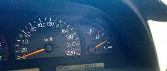
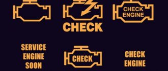
- The Check Engine light comes on immediately when starting the engine, when driving downhill or accelerating;
- the engine starts to misfire for no reason;
- the car accelerates poorly, its dynamic characteristics deteriorate significantly.
All these symptoms can be considered individually or in combination. If at least one of them appears, it is better to first diagnose the sensor so as not to disassemble the engine for nothing.
In addition, diagnostic work is also necessary if the on-board computer displays one of the following knock sensor error codes:
- This code does not indicate a problem with the high voltage wires;
- Most likely, the error code means oxidation of the contacts, which should be carefully cleaned to restore normal operation of the device. The problem may also be caused by a break in the wiring that supplies current to the knock sensor;
- 0326-0327. These codes indicate that the signals from the sensor to the controller are too weak. The main reasons are the same oxidation of contacts or weak fixation of the sensitive element.
Execution algorithm:
- Remove the sensor from the engine block.
- Turn on the voltmeter/multimeter with an operating mode of 200 mV.
- Connect the multimeter electrodes to the knock sensor terminal. Use a screwdriver to tap on the DD housing.
- When tapping, you need to monitor changes on the device display. The voltmeter readings should change with impacts of different strengths and frequencies. If this does not happen, the sensor is faulty and needs to be replaced.
Types of knock sensors for VAZ cars:
- resonant (barrel-shaped);
- broadband (tablet-shaped).
These sensors vary greatly, so before purchasing a new one, you need to understand which one you need.
Checking DD on video:
Other articles about VAZ sensors:
Where is the knock sensor located in a VAZ-2115 car?
So, as we have already found out, the knock sensor, located directly on the engine block, closely monitors its operation immediately after starting. The exact location of the device is the gap between 2 and 3 cylinders. Finding it is not at all difficult, especially if you have experience in repairing your car and have repeatedly overhauled the engine.
The knock sensor can be either one-stroke or two-stroke - it depends on the configuration of a particular machine. In addition, all devices are divided into two main types:
- broadband sensors, which are round in shape and resemble a large tablet;
- resonant highly sensitive elements made in the shape of a barrel.
These types of sensors are not interchangeable, so before choosing a replacement product, you need to know which element is installed on your machine.
As practice shows, this device is very reliable; it can work for many years without creating virtually any problems. But sometimes even this sensor fails.
Independent check and replacement of injection sensors - phases and detonation on VAZ 2114 and 2115 8 valves
VAZ 2114 car engines are equipped with a variety of devices and controllers designed to ensure proper operation of the unit. The performance of the engine and the main systems of the Four depends on their coordinated work. Where is it located and how to replace the VAZ 2114 8 valve phase sensor (DF), as well as the knock sensor (DD)? Detailed instructions are provided below.
Types of sensors
The VAZ 2110 is equipped with two types of knock sensors: broadband or resonant. Wideband constantly captures the entire spectrum of noise and also signals about it. After this, the signal is processed and engine operation is adjusted accordingly.
Wideband knock sensor
Resonant ones do the same thing, but their difference is that they give a signal only when the detonation changes. But in fairness, it should be noted that both of these types of devices are very reliable in operation; their malfunctions are the exception rather than the rule, and therefore replacement is not often required.
Resonant knock sensor
The main reason should be sought in the fact that somewhere there is a break in the electrical circuit, after eliminating which the sensor will again give correct readings.
Description of the phase sensor
First, let's look at the installation location, purpose, and design features of the DF.
Location, purpose and device
In VAZ 2114 and 2115 cars, the phase sensor is a device used to obtain information about the operation of the power unit and further transmit this data to the control unit. By design, the device of this controller includes a sensitive element and a signal converter. The conversion mechanism consists of an operational amplifier, a special bridge circuit, and an output stage.
Inside the device there is a sensitive element, the operating principle of which is based on the Hall effect. The main purpose of the sensitive component is to supply a signal at a certain moment, at which a magnetic conductive element will be located next to the board.
Where is the DF located in the Fours? The location of the device may differ depending on the engine variation:
- in engines with 8 valves, the DF is located directly on the cylinder head;
- in 16-valve engines, the DF can be found on the side of the drive camshaft, not far from the generator unit.
Possible problems and solutions
What are the signs that indicate a controller malfunction:
- fuel consumption in the car has increased;
- a problem occurred in the operation of the car’s self-diagnosis system;
- the dynamics of the vehicle as a whole has decreased;
- new errors appeared on the dashboard - 0343, 0340, sometimes there are no errors, but there is a Check Engine indicator (appears in case of complete failure of the device).
Instructions for diagnosing and replacing DD
How to check the continuity and functionality of the DF with a multimeter?
The diagnostic procedure differs depending on the modification of the power unit; to check the DF on an 8-valve engine, do the following:
- First, you will need to set the voltage value to 13.5 volts at the pin of the marking tester V1, this probe must be connected to pin E. Then, at the second pin connected to pin B, you should set the voltage value to 0.9 volts.
- When the contacts of the circuit are closed, you need to bring an awl or a screwdriver to the side of the controller, you can also use a metal plate. If the phase sensor is working correctly, then you will see the voltage value at pin B drop to 0.4 volts. If the values obtained during diagnostics differ, this indicates that the regulator must be replaced (video published by the channel In Sandro's Garage).
In the case of 16 valves, the verification procedure is generally the same, but there are certain differences:
- The tester should be set to V2 mode, and on pin E the voltage should be set to 13.5 volts. Pin B is set to 0.4 volts.
- Then you also need to bring a screwdriver or a steel plate to the end of the housing. During normal operation of the controller, the voltage value will increase to 0.9 V.
Operating principle of DD
The functionality is based on the operation of a piezoelectric element. A piezoelectric plate is mounted inside the DD structure. When detonation occurs, tension is created on the plate. The voltage is not great, but quite enough to create oscillations.
The higher the frequency, the higher the voltage. When fluctuations exceed the maximum range, the electronic control unit automatically adjusts the angle of the ignition system towards a decrease. The ignition is advanced.
When the oscillatory movements disappear, the ignition angle is restored to its original position. Thus, maximum operating efficiency of the power unit is achieved under specific operating conditions.
If the engine fails, the “Check Engine” error appears on the dashboard.
Description of the knock sensor
Now let's talk about the knock sensor. Let's start with the location and purpose of the controller.
Location, purpose and device
The DD in the Four is one of the main elements that determine the correct operation of the power unit. The main design element of the knock sensor is the piezo mechanism. When a load is applied to the knock sensor, the device generates an electrical pulse that is sent to the control module. The block detects the occurrence of detonation in engine operation, according to which it changes the ignition timing.
As for the location, in the VAZ 2114 the DD is located on the engine cylinder block, between cylinders numbered 2 and 3. If your car is equipped with an 8-valve engine, then you will immediately see the controller when you open the hood. As for 16-valve internal combustion engines, in this case it will be more difficult to find the sensor, since the view is blocked by the cylinder head.
Possible malfunctions and ways to eliminate them
What signs can be used to identify problems with the detonation controller:
- a significant drop in power, which is especially evident during acceleration;
- a Check icon appeared on the instrument panel;
- when you sharply press the gas pedal, detonation may be heard - a metallic knock, as experts say - “fingers” knocking;
- In some cases, the engine may overheat.
Controller failure is usually caused by regular use of low-quality fuel.
Instructions for diagnosing and replacing the controller
The diagnostic procedure can be carried out either using a tester or using an ohmmeter. When using a tester, the device itself will need to be connected to the connector for testing and diagnostics of performance. If you only have an ohmmeter, then you will need to measure the voltage between the controller contacts.
How to check the functionality of the DD:
- First, the measuring limit of 200 mV is set on the voltmeter.
- Then it is necessary to connect the probes of the diagnostic device to the contacts of the regulator.
- After this, try lightly tapping the controller body with a screwdriver or other similar tool. When you tap on the case, the voltage value on the tester display should increase to 20-40 mV, in this case it all depends on the force of the blow. If there are no changes as a result of the impact, then you need to change the DD to a new one (the author of the video is Alexander Dmitriev).
To perform the replacement you will need to do the following:
- Prepare standard plumbing tools - wrenches and screwdrivers; you will also need sandpaper or a steel brush. Turn off the power unit and turn off the ignition, and then open the hood.
- Then you will need to find the DD, press the latch and disconnect the wiring connector from the knock regulator.
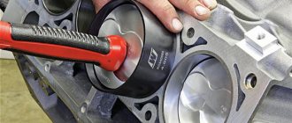
- Using a wrench of the appropriate size, you need to unscrew the nut with the stud (if your car has a two-pin DD). If a resonant type controller is installed on the engine, then you need to remove the piezo element.
- After this, the contacts on the connectors will need to be cleaned with sandpaper or a wire brush - remove all dirt and oxidation. If this is not done, problems may arise in signal transmission - the pulse will not be accurate. When the cleaning is complete, install a new one instead of the old one.
Checking the functionality of the sensor
It happens that the sensor fails due to the presence of traces of corrosion on it. In this case, you should clean the case with sandpaper and check the functionality with a multimeter.
The check is carried out as follows:
- Using a multimeter, we connect the wires to the two contacts of the broadband sensor (in the case of a resonant one, the negative wire is connected to the body, and the plus wire is connected to the center of the sensor - approx.).
- Then, using a screwdriver or any other metal object, we apply small blows to its body.
Functional knock sensor.
Depending on the force of the impact, the values on the screen of the measuring device should fluctuate between 40 and 200 MV if the sensor is working properly. And if it is broken, the value will be “0”.
If during measurements it is established that the sensor is working, a further cause of the malfunction should be sought in the wires. The pad may need to be replaced, because it is the one that is exposed to strong environmental influences, as a result of which the contacts on it rust.
Independent check and replacement of phase injection and knock sensors on VAZ 2114 and 2115 8 valves
VAZ 2114 car engines are equipped with a variety of devices and controllers designed to ensure proper operation of the unit. The performance of the engine and the main systems of the Four depends on their coordinated work. Where is it located and how to replace the VAZ 2114 8 valve phase sensor (DF), as well as the knock sensor (DD)? Detailed instructions are provided below.
Measurements
Now you can check with a multimeter set to the minimum value. If the sensor is single-contact, then the negative wire of the multimeter (it is usually black) is connected to the place where the mounting bolt is installed, and the positive wire (usually red) is connected to the signal contact in the connector.
Checking the two-contact sensor is carried out by connecting the multimeter wire to the corresponding contact “-” to “-”, “+” to “+”. Further actions are identical. To activate the sensor, you need to tap it with something not very hard (for example, a screwdriver).
If there are no faults, voltage surges will be observed. Approximately 40 to 200 mV. In addition, it would not hurt to check the internal resistance, which should tend to zero. If you find that the sensor is fine, then look for an open circuit. In this case, the best advice is to replace the entire block with wires.
If the resistance is different, or there are no voltage surges, it means that there is something wrong with the sensor itself and it needs to be replaced. The new one is installed in the reverse order of removal.
1. Check the presence and reliability of the connection of the harness socket to the sensor plug.
2. If the connection is normal, then disconnect the socket of the wiring harness from the sensor, remove its rubber cover and inspect the condition of the socket contacts and the wires connected to it. If necessary, straighten the connector contacts or replace them.
3. To check the malfunction of the harness circuit, disconnect the sensor and the unit from the wiring harness and, with the ignition off, check the integrity of circuit “11” of the harness with an ohmmeter: from contact “2” of the sensor socket to contact “11” of the block socket. If necessary, restore the indicated circuit.
4. After eliminating the malfunction, turn on the ignition and check that there is no fault code “041”.
Broken shield braid of the knock sensor wire
1. Check the presence and reliability of the connection of the harness socket to the sensor plug.
Description of the phase sensor
First, let's look at the installation location, purpose, and design features of the DF.
Location, purpose and device
In VAZ 2114 and 2115 cars, the phase sensor is a device used to obtain information about the operation of the power unit and further transmit this data to the control unit. By design, the device of this controller includes a sensitive element and a signal converter. The conversion mechanism consists of an operational amplifier, a special bridge circuit, and an output stage.
Inside the device there is a sensitive element, the operating principle of which is based on the Hall effect. The main purpose of the sensitive component is to supply a signal at a certain moment, at which a magnetic conductive element will be located next to the board.
Where is the DF located in the Fours? The location of the device may differ depending on the engine variation:
- in engines with 8 valves, the DF is located directly on the cylinder head,
- in 16-valve engines, the DF can be found on the side of the drive camshaft, not far from the generator unit.
Possible problems and solutions
What are the signs that indicate a controller malfunction:
- fuel consumption in the car has increased,
- there was a problem with the car's self-diagnosis system,
- the dynamics of the vehicle as a whole has decreased,
- New errors 0343, 0340 appeared on the dashboard, sometimes there are no errors, but there is a Check Engine indicator (appears in the event of a complete failure of the device).
Instructions for diagnosing and replacing DD
How to check the continuity and functionality of the DF with a multimeter?
The diagnostic procedure differs depending on the modification of the power unit; to check the DF on an 8-valve engine, do the following:
- First, you will need to set the voltage value to 13.5 volts at the pin of the marking tester V1, this probe must be connected to pin E. Then, at the second pin connected to pin B, you should set the voltage value to 0.9 volts.
- When the contacts of the circuit are closed, you need to bring an awl or a screwdriver to the side of the controller, you can also use a metal plate. If the phase sensor is working correctly, then you will see the voltage value at pin B drop to 0.4 volts. If the values obtained during diagnostics differ, this indicates that the regulator must be replaced (video published by the channel In Sandro's Garage).
Removal
Where is the VAZ 2114 knock sensor located in the car? The device is located inside the 8-valve engine, near the cylinders or intake manifold, which means it won't be easy to find. You may have to remove the top of the engine, also called the head, and start searching.
After the mechanism is found and dismantled, it must be cleaned. There are two ways to clean the connector: using alcohol as a cleaning agent or using a special cleaner. The device can be placed in a plastic bag and wiped with alcohol or cleaned with a cleaning agent. In both cases the result will be almost the same.
After cleaning, allow the mechanism to dry for half an hour before installing it back into the engine. You should also check for damage to the wiring.
Description of the knock sensor
Now let's talk about the knock sensor. Let's start with the location and purpose of the controller.
Location, purpose and device
The DD in the Four is one of the main elements that determine the correct operation of the power unit. The main design element of the knock sensor is the piezo mechanism. When a load is applied to the knock sensor, the device generates an electrical pulse that is sent to the control module. The block detects the occurrence of detonation in engine operation, according to which it changes the ignition timing.
As for the location, in the VAZ 2114 the DD is located on the engine cylinder block, between cylinders numbered 2 and 3. If your car is equipped with an 8-valve engine, then you will immediately see the controller when you open the hood. As for 16-valve internal combustion engines, in this case it will be more difficult to find the sensor, since the view is blocked by the cylinder head.
Possible malfunctions and ways to eliminate them
What signs can be used to identify problems with the detonation controller:
- a significant drop in power, which is especially evident during acceleration,
- a Check icon appeared on the instrument panel,
- when you sharply press the gas pedal, you may hear detonation, a metallic knock, as experts say, “fingers” are knocking,
- In some cases, the engine may overheat.
Controller failure is usually caused by regular use of low-quality fuel.
Instructions for diagnosing and replacing the controller
The diagnostic procedure can be carried out either using a tester or using an ohmmeter. When using a tester, the device itself will need to be connected to the connector for testing and diagnostics of performance. If you only have an ohmmeter, then you will need to measure the voltage between the controller contacts.
How to check the functionality of the DD:
- First, the measuring limit of 200 mV is set on the voltmeter.
- Then it is necessary to connect the probes of the diagnostic device to the contacts of the regulator.
- After this, try lightly tapping the controller body with a screwdriver or other similar tool. When you tap on the case, the voltage value on the tester display should increase to 20-40 mV, in this case it all depends on the force of the blow. If there are no changes as a result of the impact, then you need to change the DD to a new one (video author Alexander Dmitriev).
To perform the replacement you will need to do the following:
- Prepare standard plumbing tools: wrenches and screwdrivers; you will also need sandpaper or a steel brush. Turn off the power unit and turn off the ignition, and then open the hood.
- Then you will need to find the DD, press the latch and disconnect the wiring connector from the knock regulator.
- Using a wrench of the appropriate size, you need to unscrew the nut with the stud (if your car has a two-pin DD). If a resonant type controller is installed on the engine, then you need to remove the piezo element.
- After this, the contacts on the connectors will need to be cleaned using sandpaper or a wire brush to remove all dirt and oxidation. If this is not done, problems may arise in signal transmission; the pulse will not be accurate. When the cleaning is complete, install a new one instead of the old one.
How to avoid detonation
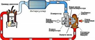
Designers are constantly struggling to solve the problem of detonation. One of the proposed options is the use of power plants with a prechamber-torch ignition system. What kind of “beast” is this? In engines of this type, two working chambers are used: preliminary and main. In the first, an enriched fuel-air mixture is formed, in the second - a lean one. When ignition occurs in the prechamber, the entire process moves to the main zone: as a result, detonation is eliminated.
The simplest way to avoid detonation is to drive at relatively high speeds, minimally use the engine operating mode “in tension” and in the range of up to 2000 rpm, which inevitably leads to the formation of carbon deposits on the valves and piston heads.
If we consider modern injection engines, then in them the described phenomenon is “observed” by the ECU. As soon as the proportions of air and fuel in the mixture begin to differ from the norm, the ignition is automatically adjusted: that is, its angle changes. However, for an infinitely long time, the ECU will not be able to adjust the parameters to a specific situation: gradually the injectors will still become clogged and the mixture will become excessively lean. If there is an on-board computer, it will display error P0324. This is exactly the case when it is necessary to check the cleanliness of the injectors, since the motor and the wires suitable to it may be in good condition.
But what to do if all of the above engine systems are working properly? The recommendations are simple: you should choose the fuel recommended by the manufacturer and refuel at a gas station that has proven itself for a long time. Then there will be no need to buy dubious additives, which, according to the inscriptions on the label, supposedly increase the octane number of gasoline.
Design and principle of operation
Principle of operation
As we know, and some only guess, the maximum efficiency of the engine (dynamics, power, fuel consumption) is greatly influenced by the correctly set ignition timing, which, moreover, must optimally adapt to different engine operating modes. Deviations from the optimal ignition timing parameters are as follows:
- A late ignition timing is fraught with deterioration in vehicle dynamics, engine overheating and increased fuel consumption;
- An early ignition timing angle, in turn, manifests itself in the form of microexplosions in the combustion chamber (detonation), which entails a drop in power and increased valve wear (valve burnout).
And in order to eliminate these deviations, the car’s electronic control unit strives to set the ignition timing as large as possible, but at the same time does not allow it to go into the detonation zone, which the knock sensor reports to the controller. The operating principle of this device is based on the piezoelectric effect. The knock sensor is mounted on the engine block.
OPERATING PRINCIPLE AND FUNCTIONAL PURPOSE
Let's figure out what a knock sensor is used for using its typical operating cycle as an example.
When the engine is operating in normal mode, the DD, roughly speaking, sleeps. However, when detonation begins to occur inside the cylinder block, the sensor reacts to its power and sends a corresponding signal to the ECU. Based on the information received, the controller changes the ignition angle until detonation in the fuel combustion chambers disappears.
What does the knock sensor of the VAZ 2114 affect? Without it, the electronics of the fourteenth cannot set the correct ignition timing, which threatens engine malfunctions: if the timing is smaller than necessary, as a result of micro-explosions, the engine will not be able to produce its usual power, and the valves in the cylinders will wear out quickly. More than necessary - gasoline consumption will increase, acceleration dynamics will decrease, and the engine itself will constantly overheat.
The operating principle of the knock sensor is based on piezoelectric effect technology. Inside the metal body of the device there is a plate that is highly sensitive to the force of mechanical influences exerted on it.
The device is the simplest
When detonation occurs in the engine, vibration is transmitted to the plate, which is converted by the sensor from mechanical energy to alternating current. The power of the generated current depends on the strength of the shock applied to the sensor.
There are two types of DD installed on the VAZ 2114 - broadband and resonant.
- The VAZ resonant knock sensor has a cylindrical shape. It is sensitive only to micro-explosions whose power is above a certain level;
- Broadband devices, on the contrary, are sensitive to all vibrations occurring in the engine, information about which they transmit to the ECU, and the electronics, based on the magnitude of the received alternating voltage, themselves determine whether detonation has occurred in the engine.
Resonant and broadband devices are not interchangeable, so if replacement is necessary, carefully select a new DD.
The cost of a new DD varies from 250 to 700 rubles for sensors of any type. We do not recommend taking domestically produced devices, since reviews from owners of fourteenth devices indicate that they have an extremely low working life. Moreover, under the guise of DD, ordinary dummies in an identical body, but without any functional filling, are often sold.
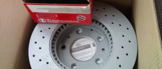
The best option is sensors produced by the German company Bosch; they cost almost 2 times more than the original VAZ ones, but at the same time they last much longer and work without problems. Also on the fourteenth you can install a VAZ 2115 knock sensor and devices for GAZ cars (article 18.3855), their mounting sockets are completely similar.
Knock sensor VAZ 2114 bosch
Diagnostics and replacement of the knock sensor
Symptoms of a problem
If you begin to notice that your car’s engine is running unevenly (troiting), or its dynamics have deteriorated and the “CHECK ENGINE” indicator lights up on the instrument panel when you start to climb or when accelerating, then you should check the knock sensor for possible malfunction. The following instructions will help you diagnose and replace the knock sensor yourself.
Examination
So, on VAZ 2110, 2112, 214, 2115, replacing the knock sensor begins with reading engine fault codes:
- Error code 0325 indicates that there is a break in the electrical circuit of the sensor circuit.
It is necessary to carefully inspect and, if necessary, “ring” the entire circuit and clean the contacts in the sensor connectors, since the main cause of this error is oxidized contacts. In addition, it is necessary to check the timing belt, namely, whether it is installed correctly according to the marks; perhaps it has become loose and has jumped several teeth.
- Error number 0328 indicates a high signal level from the knock sensor.
In this case, you need to pay attention to high-voltage wires. This error is issued when there is a breakdown of the power supply and the piezoelectric element, as well as when the valve clearance is increased. Again, recheck the timing belt.
- Error codes 0326 and 0327 indicate that the signal level from the sensor is too low.
As in previous cases, we check the electrical circuit circuit; with the sensor removed, we treat the sensor and its contacts with special anti-corrosion agents. Pay special attention to the tightening torque of the sensor, which should be 10-24 N*m. If the instrument panel does not signal you with the “CHECK ENGINE” indicator light, then replacing the knock sensor on VAZ 2114, 2110, 2115 is accompanied by checking it with a voltmeter, for which:
- In the multimeter, set the voltmeter mode and enter the reading limit of 200 MV;
- On a two-contact sensor (broadband type) we connect the multimeter probes to the contacts, and on a one-contact (resonance type) - one to the contact, the second to the sensor body;
- Lightly tap the sensor body with a subsequent increase in impact force with a metal object (screwdriver or bolt) and observe the voltmeter readings;
- When impacted, a voltage surge should be observed: a stronger impact means a higher surge, otherwise the sensor definitely needs to be replaced.
Also, replacing the VAZ 2115 knock sensor may be accompanied by checking it with an ohmmeter, in which the resistance reading should be on a scale of 1-10 MOhm.
Replacement
Replacing the knock sensor of a VAZ 2112, 2110, 2114, 2115 is not difficult at all, so this instruction will not contain any additional video materials. As mentioned above, sensors of both types are installed on the engine cylinder block. The entire replacement process is as follows:
- With the ignition off, disconnect the wire connector from the sensor, or one wire for a resonant type of sensor;
- In the first case, use a key set to “13” to unscrew the bolt securing the engine...
Replacing the knock sensor VAZ 2115
VAZ 2110 knock sensor replacement
...and in the second, using a key set to “22”, we unscrew the block from the body and dismantle the device itself;
- Install in reverse order.
Advice! When installing, pay special attention to the cleanliness of the sensor seat and its tightening torque (10-25 N*m)
How to check the knock sensor and replace it yourself on a VAZ 2112
Notification of the presence of a system error on the dashboard does not guarantee 100% malfunction of the DD. Sometimes it is enough to limit yourself to preventive maintenance, purging, and the functionality of the equipment is restored.
In practice, few owners know or use this. Most often, they are replaced with a new one. This is not always rational from an economic point of view.
Sudden alarm activation occurs after washing the car, driving through puddles, or in rainy weather. Water penetrates inside the controller, the contacts close, and a power surge occurs from the circuit. The ECU regards this as a system error, giving a signal on the device in the form of P2647, P9345, P1668, P2477.
To ensure objectivity of the data, carry out comprehensive diagnostics using digital equipment. In “garage conditions”, use a device such as a multimeter. The sensor is available to most car enthusiasts.
If the device is not available, it can be purchased at any auto store, car market, or online catalogues.
Description of the concept and mechanism of detonation
Detonation occurs when the pressure on the fuel-air mixture (FA) is higher than normal. As a result of greater impact on the accelerator pedal, the pressure in the cylinder increases and the piston cannot reach the top point of its movement. The fuel assembly ignites much earlier, creating a shock wave effect.
The generated heat is distributed throughout the combustion chamber and piston, creating overheating. The unburned fuel mixture reacts with engine parts and can be deposited on the walls in the form of aldehydes or alcohols, causing corrosion. In the future, these chemical compounds can aggravate detonation.
The wave from an explosion in high temperature conditions propagates throughout the chamber at a speed of up to 1000–3000 m/s. Under normal combustion conditions of the fuel-air mixture, the wave speed reaches 20–30 m/s.
Consequences of detonation
When fuel combustion technology is disrupted, the temperature in the cylinders constantly rises. As a result, the spark plugs are the first to be hit, followed by the valves and piston rings.
During detonation, an oil film burns out on the engine, which should protect parts from excessive wear. In the long-term absence of a lubricant, the elements of the cylinder-piston group are subjected to excessive mechanical stress, which is fraught with the occurrence of rings and scuffing on the walls of the combustion chamber.
In addition to the temperature load, constant pressure arises from the shock wave, which overtakes all active elements of the engine. First of all, this is reflected in the crank mechanism.
The bearings that suffer the most from detonation are the crankshaft and connecting rod.
Causes of engine detonation
There are several main reasons that contribute to detonation:
- Composition of the fuel-combustible mixture. When ignited, an excessively enriched fuel assembly can create oxidizing compounds on the walls and corners of the chamber, which lead to further engine detonation. This most often happens with fuel assemblies with an air/fuel ratio of 9.0.
- Ignition timing. If the ignition system has been tampered with, there is a high probability of an increase in the shock load on the pistons. The pressure exerted on the mixture causes it to spontaneously ignite.
- Octane number. The likelihood of engine detonation increases if you use gasoline with a low octane number. Thus, cars that run on 75 gasoline, instead of the recommended 92, are more susceptible to detonation.
- Compression level. Compression is the relationship between the volumes of the combustion chamber and the piston. An increase in the indicator increases the temperature in the cylinders and leads to detonation. To avoid this problem, it is better to use high octane gasoline for cars with high compression. Problems with the fuel filter or the fuel pump works intermittently.
- Defects in the operation of the oxygen sensor due to which the fuel assemblies are mixed in incorrect proportions.
- Cooling problems.