Why did it happen so?
Perhaps the automatic requests do not belong to you, but to another user accessing the network from the same IP address as you. You need to enter the characters into the form once, after which we will remember you and be able to distinguish you from other users exiting from this IP. In this case, the page with the captcha will not bother you for quite a long time.
You may have add-ons installed in your browser that can make automatic search requests. In this case, we recommend that you disable them.
It is also possible that your computer is infected with a virus program that is using it to collect information. Maybe you should check your system for viruses.
If you have any problems or would like our support team, please use the feedback form.
Let's look at how the front suspension of the VAZ 2110 is designed, how well it complies with modern standards, what functions it provides, and what attention it requires.
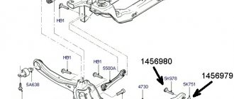
What is needed to diagnose and replace the VAZ 2110 silent block
- Spare parts from the VAZ catalog number 2110 2914054
- Two spanners No. 19
- Sledgehammer or hammer
- Chisel
- Two jacks
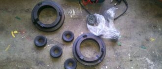
- Device for manually pressing in a new silent block
- Wooden blocks
Thus, it is not difficult to understand how to check silent blocks on a VAZ 2110; it is more difficult to carry out this procedure using all the accumulated knowledge. A machine is a complex mechanism, a well-coordinated system, so all repair work should be carried out comprehensively and slowly.
Main nodes
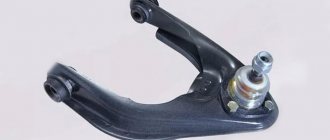
Let's talk about its device. The most important element of the front suspension is its strut (hydraulic telescopic) - indispensable in the matter of shock absorption, that is, ensuring a comfortable ride, without much shaking (as far as possible) over bumps and potholes on our roads. It is thanks to the rack, or rather its steering knuckle with an upper bolt equipped with an eccentric washer and a belt, that makes it possible to change the camber of the wheel.
Telescopic strut of the front suspension of VAZ 2110
The following are installed on the rack:
- Special spring;
- Buffer limiting the compression stroke, made of polyurethane;
- Upper support. Its structure is as follows: it is attached to a stand, to which the mudguard is attached with self-locking nuts. Therefore, if you make repairs yourself, do not miss this moment - you cannot use ordinary nuts;
- A bearing that makes it possible to rotate the stand together with the wheels;
- A shock absorber in which a spring and a plunger are installed for better performance.
The ball joint combines the lower parts: the steering knuckle and the lever. The longitudinal braces, lower arms, and supports that the crossbar has are connected to each other by rubber-metal hinges. With the help of special washers, it becomes possible to adjust the longitudinal inclination of the turning axis. An angular contact, non-adjustable bearing secures the wheel hubs.
Ball joint VAZ 2110
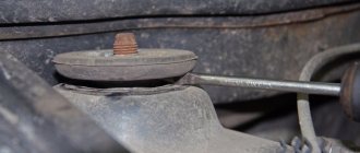
The cross member is the rod to which the lower arms are connected. It is attached to the body in the middle, helped by rubber cushions. This, in a nutshell, is the front suspension design. Now let’s look at possible malfunctions, which in some cases can be fixed with your own hands, in others it is better to contact specialists.
Cross member VAZ 2110
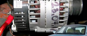
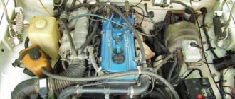
VAZ 21099 Engine and its systems
1.Unscrew the fastening bolts and remove the crankcase protection.
2. Remove the muffler exhaust pipe (see subsection 11.6.1.). 3. Remove the air filter (see subsection 11.2.).
4. Loosen the clamp and disconnect the brake booster vacuum hose from the engine inlet pipe. 5. Unscrew the bolt and disconnect the ground wire from the clutch housing. 6. Loosen the clamps and disconnect the hoses from the thermostat.
7. Disconnect the high-voltage wire from the central terminal of the ignition distributor cover. 8. Use a screwdriver to press out the spring clip and disconnect the block with low-voltage wires from the ignition distributor terminal.
9. Loosen the clamp and disconnect the fuel supply hose from the fuel pump.
10. Loosen the nuts on the end of the clutch release cable. 11. Remove the cable end from the clutch release lever. 12. Disconnect the block with the wire from the starter traction relay terminal.
13. Unscrew the fastening nut and disconnect the wire from the contact bolt of the starter traction relay. 14. Disconnect the block with the wire from the generator terminal. 15. Unscrew the nut and disconnect the wires from the generator terminal.
16. Disconnect the connector with the wire from the carburetor shut-off solenoid valve terminal. 17. Loosen the clamp and disconnect the fuel return hose from the carburetor. Remove the hose from the plastic clamp. 18. Loosen the bolt securing the choke rod to the choke control lever.
19. Loosen the bolt securing the air damper drive rod shell to the bracket and disconnect the cable. 20. Remove the spring clamp of the accelerator drive cable from the throttle valve drive sector. 21. Remove the throttle actuator return spring.
22. Remove the accelerator drive cable from the throttle valve drive sector. 23. Unscrew the fastening nut and remove the accelerator cable bracket from the valve cover. 24. Disconnect the block with the wire from the limit switch of the forced idle economizer (EFH).
25. Disconnect the wire from the coolant temperature sensor. 26. Disconnect the wire from the oil pressure sensor. 27. Loosen the clamp and disconnect the heater supply hose.
28. Loosen the clamp and disconnect the heater outlet hose. 29. Loosen the clamp and disconnect the gear shift rod from the joint tip. 30. Unscrew the fastening nut and disconnect the cable from the speedometer drive.
31. Disconnect the block with the wire from the reverse light switch on the gearbox. 32. Loosen the nuts securing the left and right braces to the suspension arms. 33. Unscrew the three bolts securing the brace bracket to the body and move the left and right braces to a position so that they do not interfere with the removal of the power unit.
34. Remove the cotter pin from the tie rod ball joint nut to the swing arm. 35. Unscrew the nut securing the steering rod ball joint. 36. Press the steering rod ball joint pin out of the strut swing arm using a special puller.
37. Remove the two bolts and disconnect the ball joint of the suspension arm from the steering knuckle. 38. Using a pry bar, press the shank of one of the inner CV joints of the drive shafts out of the gearbox and move it to the side. 39. Insert a technological mandrel (for example, an old internal CV joint) instead of the hinge so that the side gear does not turn. After this, disconnect the second CV joint in the same way as the first.
40. Unscrew the three mounting bolts and remove the clutch housing shield. The operations specified in paragraphs 40 and 41 are performed to facilitate work on the removed engine with the gearbox. 41. Loosen the three bolts and nuts securing the clutch housing to the cylinder block. 42. Hook the engine onto the eyelets and tighten the hoist cables.
43. Unscrew the two nuts securing the rear support of the power unit to the body. 44. Unscrew the nut, slightly lift the engine and remove the bolt of the right front power unit support. 45. Unscrew the nut and remove the bolt of the left front support of the power unit.
46. Lower the engine onto stands, lift the car and remove the engine from under it.
Before lowering the engine, check that all wires and hoses are disconnected from the engine.
Suspension check
Knowing the meaning and design of the suspension, you will be able to check its condition every time you inspect the machine on a pit (overpass) and perform maintenance. Pay special attention to the condition of the protective covers on the ball joints. Check to see if any deformations, cracks or dents have appeared on the suspension due to shaking and bumps.
Be sure to check the condition of all rubber and rubber-to-metal parts, as well as the ball joint of each wheel. Remember: a malfunction noticed and corrected in time is much less evil than repairs when everything is already falling apart.
Suspension modifications
Many owners of the VAZ 2110 do not consider the factory suspension to be ideal, and tune it to improve stability and handling on the road.
Suspension is a very important component of a car. Your safety, driving control and comfort depend on its condition. Knowing how to diagnose a suspension yourself, you can save a lot of money at car services, where they charge very good money for this procedure.
It doesn’t happen that suspension parts fail overnight (unless, of course, you fly into a curb, or something worse). Usually the suspension breaks gradually. First, one element begins to tap on bumps, since it no longer works properly, its load falls on other elements that are not designed for this. They wear out faster. All this grows like a snowball, and ultimately, it all results in malfunctions of the front and rear suspension and large financial costs.
To avoid this, we will consider the most important topic - diagnosing the car suspension with your own hands. You can print out this article and hang it in your garage as a reminder, and if you suspect something is wrong with the suspension, check it immediately and don’t put it off.
There are a huge number of car suspension options. The differences lie in driving characteristics and the price of maintenance and, of course, its condition. The main structural elements remain unchanged.
The main suspension elements include:
- Shock absorbers
- Levers
- Springs
- Ball joints
- CV joint
- Wheel bearings
- Stabilizer's pole
Let's take a closer look at how a car's suspension is checked and identify its malfunction, if any. Let's start with springs and shock absorbers.
Purpose and structure of the VAZ-2112 body
The body of the VAZ-2112 car is a five-door hatchback that combines the best design features inherent in models of the tenth family. VAZ-2112 has a more modern design and sporty character compared to the prototypes.
Since 1999, production of the VAZ-2112 model began with a five-door hatchback body shortened to 4170 mm and a trunk volume of 400 liters, due to which it has clearer reactions to steering wheel rotation. The “twelfth” has its own, more sporty handling character, but in terms of comfort this car is very different for the better from the 2109 with a similar body type.
The VAZ-2112 car combines all the design features and the “stuffing” of the VAZ-2110, and the rear seat of the 2111 station wagon. While maintaining all the positive qualities of the LADA-110 car, this car has additional advantages: with a short body length, it is possible to increase a small luggage compartment into a large one when folding the rear seat. The rear seat back is divided into 2 parts, which can be folded independently of each other, thanks to which the convenience of a “station wagon” is maintained when transporting small-sized cargo.
The set of standard equipment includes a sunroof, electric windows, an immobilizer, central locking, an electric trunk lid lock, electric heated front seats, and a “Lux” interior. Additionally, power steering and anti-lock brakes can be installed.
windshield replacement body
Rice. 1. Body frame parts: 1 — radiator grille; 2 — radiator frame; 3 — upper cross member of the radiator frame; 4 — right front wing; 5 — front panel; 6 — hood hinge; 7 — hood; 8 — right front door; 9 — wind window pillar; 10 — interior panel of the front door; 11 — inner panel of the rear door; 12 — right rear door; 13 — roof reinforcement; 14 — left side; 15 — roof panel; 16 rear suspension spring support; 17 — trunk lid; 18 — inner panel of the trunk lid; 19 — side window frame; 20 — rear bumper; 21 — rear pillar; 22 — left rear door; 23 — rear wheel arch; 24 middle floor; 25 — spare wheel niche; 26 — central pillar; 27 left front door; 28 — front pillar; 29 — front floor; 30 — left front fender; 31 — front suspension spring support; 32 — bracket; 33 — front spar; 34 — bracket for towing eye; 35 — front panel; 36 — front bumper.
Shock absorbers
Shock absorbers of telescopic struts play a very important role in a car - they dampen body vibrations and are responsible for the stability of the car on the road when performing maneuvers.
It is quite easy to check the performance of shock absorbers. To do this, pick up and rock the car when it is standing on a flat surface. After you stop trying to rock the car, it should stop. If the rear shock absorbers or front ones are faulty, it will continue to sway.
If the shock absorbers are faulty, operating the car becomes problematic. The car feels unassembled and there are breakdowns on some uneven surfaces.
You definitely need to drive the car into a pit or overpass and see if there are any leaks on the shock absorbers - if there are any, then the shock absorber is not in order and should be replaced.
For a deeper analysis of worn parts, you need a special vibration stand for suspension diagnostics. You won’t be able to assemble such a stand with your own hands, and buying it for private use will also be expensive, so it’s best to fork out a few hundred rubles and contact a service to perform this procedure.
Springs
The next step in diagnosing the chassis will be diagnosing the springs. It starts with their visual inspection. If the spring is cracked, or worse, burst, then it needs to be replaced. Particular attention should be paid to the coils of the spring. If they are close to each other, or even touching, this indicates that the metal of the spring is “tired”; it is better to change such a spring.
It’s also worth measuring the car’s ground clearance and comparing it with the ground clearance it had from the factory; if it’s lower, then the springs have sagged.
If the springs are faulty, the car will roll, there will be rolls in corners, and breakdowns in the suspension. Driving such a car will be difficult.
Most springs deteriorate due to natural reasons. If the car was a workhorse, carrying various heavy loads, this may cause premature wear.
In large cities, reagents negatively affect the properties of the spring, causing corrosion and thereby reducing the thickness of the coil.
Ball
In order to make the suspension diagnostics more complete, it is necessary to check the ball joints. A ball joint is an element that connects a movable hub and a fixed suspension arm. Ball joints often fail due to fast driving on bad roads.
If there is wear on the balls, a dull sound will be heard. It will be especially obvious when driving over uneven surfaces.
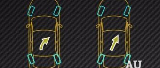
You can accurately diagnose ball joints using two methods:
- Side to side rocking method. To do this, you will need an assistant who will check for knocking in the wheel area during rocking. If it is, do not rush to judge the ball joints, check using the second method.
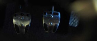
- To implement the second method, it is necessary to jack up the car, observing safety methods. To eliminate the possibility of bearing play, you need someone to press the brake pedal. At this moment, you need to rock the wheel by holding the top and bottom points (as on the 12 and 6 o’clock dial). If you feel noticeable play, then the support needs to be changed.
Supports and stabilizer links
Stabilizer links fail more often than any other suspension element. Their malfunction is expressed in a distinct rattling and tapping noise on bumps.
If, when you release the steering wheel, the car throws you out of the rut, you have to constantly steer and align it, this indicates that the stabilizer links are faulty.
In order to check the stabilizer link, you need to grab it with your hand, or find a stop and shake it with a mounting tool. If loosening occurs without much effort, a knock is heard or play is felt, then the rack needs to be changed.
Steering rack
The steering rack very often begins to knock when driving at high speed on bad roads. A knocking sound from the steering rack indicates that it needs to be repaired as quickly as possible. If this is not done, then in the future you may end up having to replace the steering rack, and this is very expensive.
The steering rack often begins to knock on cars that have a very stiff and compressed suspension. It does not absorb the full force of the impact, and part of the impact falls on the steering rack. Special crackers are installed in the steering rack, which are needed to prevent the shaft from playing. Over time, these crackers wear out, and constant impacts that the suspension does not dampen accelerate this process. The rack begins to knock. The knock is very similar to the knock of the stabilizer struts.
To check the rack, you need to climb into the hole, or remove the wheels, and pull the rack shaft, first on one side and then on the other. If beating is felt, the rack needs to be repaired.
It will also be useful to know that one of the characteristic signs of this malfunction is a kickback in the steering wheel when driving over uneven surfaces.
Body features dozens
The VAZ 2110 or simply “ten” is equipped with a load-bearing structure body. This is a 4-door front-wheel drive sedan that has adopted some features from its predecessor, the VAZ 21099.
Control dimensions of the VAZ 2110 body
In fact, the VAZ 2110 was predicted as a modification of the G8 back in 1983. Later, this base was used for the manufacture and production of a completely new car. In the meantime, the designers decided to modify the VAZ 2108 into 21099, leaving the idea of creating a VAZ 2110 for the future.
VAZ 2110 station wagon
The “ten” entered mass production only in 1991. The production of the new sedan, which, unlike its relatives, does not, oddly enough, have its own name, was continued at VAZ in 1995. Three years later, they started producing a station wagon.
Note. The VAZ 2110 at that time was the only model whose body was sold in three ways.
By 1996, the VAZ 2110 was losing its popularity, which can be explained by significant progress in the global automotive industry. A modern and progressive car, once technologically advanced, represented by the VAZ 2110, ceases to be such and loses its attractiveness. Although, on the other hand, this would not have been said at that time about the sedan, which still sells well to this day.
Bare body of VAZ 2110
It was in 1996 that the “ten” began to be mass-produced in a sedan body type. The designers modernized a number of body elements and introduced various innovations. For example, one of the innovations is the introduction of gas stops into the hood of a car.
The VAZ 2110 was considered an expensive car at that time. And this is not surprising, because the engineers of the domestic automobile industry tried to modernize this car as best as possible. They even included the possibility of installing an air conditioner in the cabin. The trunk turned out to be a sight to behold – large and roomy.
True, the sedan could not compete with the station wagon in terms of luggage compartment capacity, but the same cannot be said regarding ease of use. So, due to an unsuccessful design, the hinges on the station wagon took up a considerable part of the useful volume of the trunk. In addition, the inconvenience of loading things into the trunk of a station wagon was added by the overly inflated wheel niches.
VAZ Premier and its dimensions
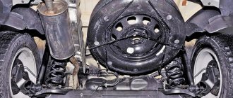
In the sedan, on the contrary, the trunk is well designed. The space for the spare tire stands out especially clearly. The wheel rim can be placed here upside down, which allows you to compactly load various things and tools into yet another free space.
As for the next modification of the “ten” called VAZ Premier, it is an exact copy of the VAZ 2110, only with an elongated body. The production of this model implied the use of an original set of body parts. They do not fit the sedan body. In addition, when designing the Premier body, engineers took care of giving it additional rigidity.
The floor was primarily reinforced. The suspension has been modernized and is more rigid than the sedan's. The total weight of the car has increased by 65 kg. As for painting, it was carried out in the same way as on the VAZ 2110 sedan.
We hope that the information provided in the article will help in your specific situation. If you will be checking the geometry and restoring it yourself, we recommend that you carefully study the photos and videos.
Tie rods and ends
The symptoms of faulty tie rod ends can be compared to the symptoms of a faulty steering rack, namely a knocking sound when driving over uneven surfaces.
In order to accurately diagnose the malfunction of these elements, you need to visually inspect the rubber parts; if they are cracked or torn, then there is a high probability that these parts are faulty.
You can check these elements for play by using a mount by rocking it up and down. If you feel noticeable play, then most likely the ball joints of the steering rods or ends are worn out.
Features of self-diagnosis
If you are diagnosing 2114 yourself, then you should be extremely careful, taking into account all the features of the work. After carrying out additional work, it is worth starting direct diagnostics. The easiest way to do this is to use a laptop with the appropriate software installed. Before starting the test, you must turn on the ignition. All work that checks the condition of the engine must be carried out with the ignition on.
Attention! Under no circumstances should you start the engine.
Then you need to connect to the connector and run the program, then everything depends on the features of the software.
On startup you may see:
- graphs with numbers;
- lists of indicators.
Already from these indicators we can draw initial conclusions about the operation of the engine. You should then receive a list of errors that the program found. You will need to decrypt the results using a text file. The text file contains all errors that may be detected.
In the table we have given a breakdown of the most common errors encountered during self-diagnosis of BC.
Wheel bearings
If the hub bearings are faulty, they produce a hum that appears when driving. This hum becomes very audible when driving on a flat road at one speed.
To be sure that it is the hub bearing and not some gearbox bearing, you need to accelerate the car a little, turn off the gear so that the car coasts. If our fears were confirmed.
To find out which bearing is humming, you need to jack up the car and spin the wheel; if you feel the characteristic grinding noise of the bearing, it means the bearing is faulty.
When the situation is very advanced, the wheel appears to have play in the vertical plane. The more the bearing is worn, the greater the play will be.
CV joints
Most often, a faulty CV joint manifests itself as a distinct crunching sound when the steering wheel is turned in any direction when driving hard. When this symptom is observed in a car, it makes sense to drive the car into a pit and check it.
In order to check the CV joint yourself, you first need to perform a visual inspection; if the boots are torn, there is a high probability that the CV joint is faulty, since the dirt that will fly under it will act as an abrasive and will accelerate wear several times.
Next, check for play. To do this, grab the drive and pull it clockwise and counterclockwise; if you feel play, it means the CV joint is faulty.
The above is not all that is included in the diagnosis. These procedures will only help determine the general condition of the main suspension components. For a more in-depth analysis of the wear of a particular element, equipment that is only available at a service station may be required.
12.1.2 Front suspension diagnostics
It is convenient to carry out all work related to technical inspection and replacement of suspension parts on a lift or inspection ditch together with an assistant. We check the tightness of the fastenings of all parts of the front suspension, tighten the loose connections. Before checking the play in the front suspension with the car standing, vigorously pump the wheel by the upper part with your hands. In case of strong knocking, check the tightness of the wheel bolts. If the bolts are well tightened, then hang the wheel and...If the knocking noise (play) disappears when the brake pedal is pressed, then its source is excessive clearances in the hub bearings (see Adjusting the clearance in the front wheel hub bearings ). Possible knocking noises may be caused by ball joints. A faulty one can be determined by touch by the play of the ball pin. We replace this hinge. We replace the deformed axis of the lower arm (this is noticeable even to the eye). If the wheel alignment angles cannot be adjusted, body deformations are possible, the mudguard struts are “overwhelmed,” the side members and cross member are bent. We recommend checking the “geometry” of the body at a service station and, if necessary, replacing the cross member.
- we hang the front wheels of the car and make sure that there is no deformation of the elements (see above);
- the radial displacement of the thrust washer relative to the outer end of the outer bushing of the rubber-metal hinge should not exceed 2.5 mm;
- the distance between the thrust washer and the outer end of the outer hinge bushing should be 3–7.5 mm for the lower and 1.5–5 mm for the upper arms.
Rubber-metal hinges must be replaced when the rubber breaks or wears on one side. We check the condition of the lower ball joints in the following order:
- Having removed the wheel, we place a strong, stable wooden block 280 mm high under the hub and lower the car onto it. For safety, place the removed wheel under the threshold of the car. We unscrew the conical plug from the lower ball joint;
We check the condition of the dirt-proof covers of the hinges. We replace the hinges with torn covers as an assembly. On the new ball joint, rotate or tilt the ball pin in different directions. Play, free movement of the finger or severe jamming are unacceptable. We carefully inspect the suspension springs. Sagging springs, as well as those with other damage, are replaced with new ones. We replace the deformed or worn stabilizer bar. When the suspension rod mounting pads wear out, replace them with new ones. There should be no play in the shock absorber mountings. We make sure that the rubber-metal hinge in the lower mounting eye has no wear - cracking, delamination, etc., its fastening bolt is tightened. If strong leaks of working fluid appear on the shock absorber body, replace it with a new one. It is recommended to replace both shock absorbers at once. You can check the serviceability of the shock absorbers with the car standing. Rock the car by pressing the wing several times in a vertical direction. Having stopped rocking the car, we make sure that the free vibrations of the body die out in no more than 2 cycles. There should not be any knocking noises.