The timing belt drive has many advantages and one major drawback. The main advantages of a belt drive are noiselessness and simplicity. The tension of a flexible toothed belt can be adjusted using one simple device consisting of a roller and a spring; it does not require numerous dampers, like a steel roller chain. Another indisputable advantage of the belt drive is the absence of the need for lubrication. For this reason, the entire drive mechanism is located outside the block and cylinder head and is covered with an easily removable plastic casing. Thanks to this, the process of inspecting and replacing the timing belt is simplified to the limit.
Belt drive design
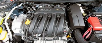
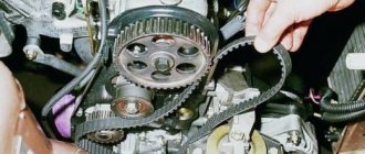
The belt drive consists of a crankshaft toothed pulley, a camshaft toothed pulley similar in appearance and design (or two shafts), a timing belt, a tension pulley (sometimes in combination with an additional idler roller or rollers), and a coolant pump pulley. Some manufacturers prefer to drive the pump using a conventional drive belt. In this case, the design of the timing belt is simplified.
The base of the timing belt and its teeth are often made of different materials
The timing belt is necessarily equipped with a power frame, which makes it possible to almost completely prevent its stretching. Due to the residual elasticity of the belt and the minimum gap in engagement, it is significantly reduced during operation of the timing mechanism. The drive belt teeth have high precision casting.
Replacing the timing belt
Replace the timing belt if, upon inspection, you find:
– traces of oil on any surface of the belt;
– signs of wear on the toothed surface, cracks, undercuts, folds or peeling of the fabric from the rubber;
– cracks, folds, depressions or bulges on the outer surface of the belt;
– fraying or delamination on the end surfaces of the belt.
| 4. Remove the belt from the camshaft pulley, tension pulley and water pump timing belt. | ||
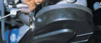
| 5. To unscrew the bolt securing the generator drive pulley, it is necessary to secure the crankshaft from turning. To do this, after removing the plug in the clutch housing, an assistant must use a mounting spatula or a large screwdriver to hold the crankshaft from turning by the flywheel ring teeth. | ||
| 6. Having unscrewed the crankshaft pulley mounting bolt, remove it with the washer and remove the generator drive pulley from the crankshaft. | ||
| 7. Remove the timing belt from the crankshaft timing pulley. | ||
| 8. Before installing a new belt, clean the pulleys and tension roller from dirt and grease, and degrease them with white spirit. | ||
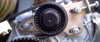
| 9. Install the timing belt in the reverse order of removal. The generator drive pulley is installed in one position. Hole 1 of the pulley should fit onto the mounting sleeve 2. | 10. When installing the belt, ensure the tension of its leading branch. After installing the belt, adjust its tension (see here). If you hear noise from the timing belt, there is a possibility that the tension pulley bearing has failed. Remove the roller, check the functionality of its bearing and, if necessary, replace the roller. | |
| 13. Check the functionality of the bearing. If, when turning the bearing, you feel jamming, axial play, or signs of grease leaking out of the bearing, replace the tension roller. | 11. To replace the roller, before installing the belt, completely unscrew the nut securing it, remove the washer, and then the roller from the stud. | 12. A spacer ring is installed under the roller. |
| 14. Install the new tension roller in the reverse order of removal. In this case, the holes for the special key should be directed outward. | ||
How often to change the timing belt
Is a belt better than a chain?
A timing belt for camshaft drive is now used on front-wheel drive VAZs and the vast majority of foreign cars. Compared to gear or chain, it is quieter and does not require lubrication (the absence of sealed covers simplifies access to the belt). On the other hand, belts are resistant to oil and gasoline. Some car owners remove the cover altogether to make it easier to monitor the condition of the belt. This should not be done - in addition to possible contact with aggressive liquids, there is a possibility of the drive jamming and teeth being cut off from a pebble or twig accidentally flying under the hood.
Change on time
The frequency of replacing the timing belt is indicated in the instructions, but it still doesn’t hurt to visually check its condition from time to time. Small cracks that appear clearly indicate the need for unscheduled replacement. It doesn’t hurt to find out in advance how fatal a broken belt is for engine parts: in other words, whether this is fraught with the valves meeting the pistons and subsequent serious repairs, or whether the matter will be limited to just adjusting the camshaft position.
The service life of the belt depends on its correct tension. A tensioned one that is too tight can break, and a loose one can jump several teeth on the pulley. In Russian passenger cars, the toothed belt also serves to drive the water pump. This allows you to use the V-belt only to drive the generator, and if it breaks, you can drive to the spare parts store using battery power (coolant circulation does not stop). At the same time, the service life of the toothed belt is reduced, and a humming pump bearing must be replaced as soon as possible - when it jams, the teeth are instantly cut off.
Drive belt tooth material and shapes
The drive belt tooth profile comes in three types. The trapezoidal tooth shape is standard. If increased performance capabilities of the drive belt are required to transmit high torques, then rounded teeth are used. Mixed-profile teeth are used much less frequently, combining the operational capabilities of the two previous types.
To maintain the longitudinal stability of the drive belt, fiberglass is used in the manufacture of the flexible cord. At the same time, the lateral flexibility of the drive belt is maintained. The belt shell, in which the cord threads are located, is made of synthetic neoprene rubber. This serves to protect the cord from dirt and oil and prevents premature wear. The drive belt teeth are also made of neoprene. They are welded to the top neoprene layer of the coating. The teeth ensure smooth transmission and optimal adhesion between the belt and tensioner rollers.
IDMG
- traces of oil on any surface of the belt;
- traces of wear on the toothed surface, cracks, undercuts, folds and peeling of fabric from rubber;
- cracks, folds, depressions or bulges on the outer surface of the belt;
- fraying or delamination on the end surfaces of the belt.
A belt with traces of engine oil on any of its surfaces must be replaced, as the oil quickly destroys the rubber. The cause of oil getting on the belt (usually a leak in the crankshaft and camshaft seals) must be eliminated immediately.
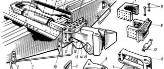
Rice. 4.13. Engine components removed when replacing the timing belt : 1 - crankshaft pulley; 2 — lower cover of the timing belt; 3 — timing belt; 4 — front cover of the timing belt; 5 — bracket for the right suspension support of the power unit; 6 - water pump pulley
Carry out the work on an inspection ditch, overpass or, if possible, on a lift.
You will need: special devices for blocking the camshafts and crankshafts and the tension roller of the timing belt, a “10” socket wrench, “8”, “13” spanners or socket heads, “18” wrench
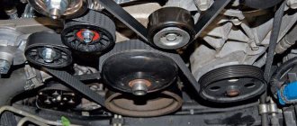
Remove the air conditioning compressor drive belt and accessory drive belt
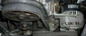
Remove the generator.
Remove the expansion tank from the brackets on the body and move it to the side without disconnecting the hoses.
Place a secure support under the engine.
Remove the right front suspension mount of the power unit by unscrewing the two nuts securing it to the bracket on the engine and unscrewing the two bolts securing it to the mudguard of the engine compartment.
Remove pulley 6 (Fig. 4.13) of the water pump by unscrewing the four bolts securing it.
Remove bracket 5 of the right suspension support of the power unit by unscrewing the three bolts securing it (Fig. 4.14).
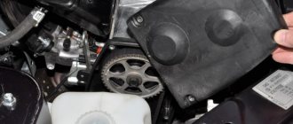
Remove the front cover 4 (see Fig. 4.13) of the timing belt by unscrewing the eight bolts securing it.
Place the gear lever in neutral.
Rotate the engine crankshaft by the bolt securing its pulley until the marks on the VVT (variable valve timing) mechanisms of the camshafts are installed, as shown in Fig. 4.15 (eleven o'clock on the clock dial).
Unscrew the plug located in the front part of the cylinder block on the right (Fig. 4.16), and install the locking rod into the opened hole until it stops against the crankshaft. Carefully rotate the crankshaft by the bolt securing its pulley until the shaft stops with the locking rod.
Rice. 4.14. Fastening the bracket for the right suspension support of the power unit
Rice. 4.15. Installation marks on VCT mechanisms
Rice. 4.16. Hole plug for installing the crankshaft locking rod
The fixing rod is a cylindrical part about 65 mm long, stepped in diameter. Part of the rod of small diameter (4 mm), 10 mm long, is a shank that fits into the groove of the crankshaft. The remaining cylindrical part of a larger diameter (8 mm) serves as a guide in the hole of the cylinder block.
Secure the camshafts from turning by installing a locking device in special grooves in the housings of the UST mechanisms (Fig. 4.17). Install the device so that the marks on the branches of the device are at the top, and the mark in the form of a line should be on the side of the exhaust camshaft, and the mark in the form of a dot should be on the side of the intake camshaft.
Engage 4th gear in a manual transmission (or set the automatic transmission selector to the “P” position - parking) and brake the car with the parking brake to prevent the engine crankshaft from turning.
Rice. 4.17. Fixing camshafts from turning with a special device
Rice. 4.18. Crankshaft pulley and its mounting
Rice. 4.19. Lower timing belt cover and its fastening
Unscrew the bolt securing the pulley (Fig. 4.18) to the toe of the crankshaft and remove the pulley.
The crankshaft pulley mounting bolt must not be reused.
Unscrew the three bolts securing the lower timing belt cover (Fig. 4.19) and remove the cover.
Loosen the tension of the timing belt by moving the driving belt branch as much as possible in the direction shown by the arrow in Fig. 4.20. In this case, the tension roller will move to its original position. Fix the tension roller in this position by inserting a metal rod of suitable diameter into the holes of the roller and its bracket.
Remove the belt from the VCT sprockets, crankshaft and tension pulley.
Do not turn the crankshaft with the timing belt removed, as the pistons will damage the valves.
Place a new belt on the exhaust camshaft VCT sprocket. Pull the drive belt and place it on the intake camshaft VCT sprocket. Next, tension the drive belt and place it on the crankshaft timing pulley. Place the driven part of the belt behind the tension roller.
Check that the belt is installed correctly on the timing pulleys and remove the locking rod from the holes in the tension roller and its bracket. In this case, the tension roller spring will set the required belt tension.
Install the lower timing belt cover and crankshaft pulley. Tighten the crankshaft pulley mounting bolt in two stages:
1st - tighten the bolt to a torque of 40 N m (4.0 kgf m);
2nd - tighten the bolt 90o.
Remove the locking device from the VCT camshaft housings.
Remove the crankshaft retaining rod from the hole in the cylinder block
Rice. 4.20. Loosening the timing belt tension
Engage neutral gear in the gearbox, rotate the crankshaft two turns and stop it in a position in which the marks on the VCT mechanism housings take the position shown in Fig. 4.15.
Install a locking rod into the hole in the cylinder block and carefully tighten the crankshaft until it is secured with the rod.
Install the fixing device on the VCT mechanism housings (see Fig. 4.17). If the device was installed without difficulty, the camshaft drive belt is installed correctly. If the device cannot be installed (the valve timing is shifted), remove the belt, install the fixing device and repeat the belt installation as described above.
If the timing belt is installed correctly, remove the locking device from the VCT mechanism housings, remove the locking rod from the hole in the cylinder block, replace the plug of this hole, tightening it to a torque of 20 N m (2.0 kgf-m), and install all The removed parts are in the reverse order of removal.
Typical failures of timing belt drives
The most common timing belt drive malfunction is a broken belt. If this happens, the crankshaft continues to rotate and the camshaft stops. The pistons, rigidly coupled to the crankshaft, continue to move up and down, but the valves remain in the same positions, and some of them may be open. Reaching top dead center, the cylinders hit the open valve plates, deforming them and bending the rods.
The likelihood of valve stem deformation in 8-valve engines is several times less than in complex systems with 16 or more valves
In simple timing designs with one camshaft and two valves per cylinder, when the belt breaks, the shaft cams, as a rule, do not hit the valve stems, and the cylinders do not hit their lower part. The reason is that the manufacturer manages to implement mechanical protection against damage in the design of the cylinder head. In other words, the valves are located in the “ceiling” of the combustion chamber so that even in the open position the valves do not reach the surface of the cylinders. In systems with a large number of valves per cylinder, this principle cannot always be implemented due to space limitations.
Timing belt (Gas distribution mechanism).
Timing Belt/Chain Diagrams >
A drive belt is an element of a belt drive that serves to transmit torque due to friction or meshing forces.
The vehicle accessory drive belt is important for transmitting torque to mechanisms such as the air conditioning compressor, power steering pump, generator, and cooling water pump (Pump).
The gas distribution mechanism (GDM) serves for the timely intake of the combustible mixture and the release of exhaust gases from the cylinders. These functions are achieved by opening and closing the intake and exhaust valves in accordance with the operating process in the cylinder.
The main timing faults include:
- wear of cams and camshaft supports;
- wear of valve stems and discs;
- wear of valve guides;
- loss of elasticity or breakage of valve springs;
- camshaft drive chain extension;
- drive belt breakage, general belt wear;
- wear of the teeth of the camshaft drive gears;
- wear of the tensioning mechanism (tensioner roller or tensioner);
- violation of the thermal gap between the rocker arm and the end of the valve stem;
Diagnosis of the technical condition of the timing belt is carried out by visual inspection and listening to noises and knocks created by timing parts, and in case of significant wear or knocking, a decision is made to send the engine for repair.
In case of wear of the valve stems and their guide bushings, there is a breakthrough of lubricating oil into the cylinder block, increased smoke in the exhaust gases, as well as oil splashing onto the spark plug electrodes and interruptions in engine operation.
When the elasticity of the valve springs is lost, the kinematic connection between the valve stem and the rocker arm breaks, and sharp metallic impacts and knocks are heard.
If there is a large gap between the valve plate and the seat, as well as when the valve seat and the seat are worn, the tightness of the working cavity of the cylinder is broken and gas breakthrough occurs, as a result of which combustion of the combustible mixture is observed in the engine intake tract or popping noises in the muffler.
During timing maintenance, the following control and adjustment work is performed:
- Checking the size of the thermal gap;
- Adjusting the tension of the camshaft drive roller chain. Replacing the timing belt according to the vehicle's mileage (regulated by the manufacturer of the vehicle). Vehicle maintenance schedule depending on mileage >
The gas distribution mechanism (GRM) consists of:
- Camshaft;
- Intake and exhaust valves with springs;
- Roller levers (rocker arm, rocker).
Timing Belt/Chain Diagrams >
The camshaft controls the opening and closing of the intake and exhaust valves.
There are three main types of configurations: OHV (Off Highway Vehicle), SOHC (Single OverHead Camshaft), DOHC (Double OverHead Camshaft)
- OHV - the camshaft is located in the engine block with rods. The pushrods transmit movement to the rocker arms, which open and close the valves in the cylinder head (cylinder head). This configuration is practically not used in modern cars. In this configuration, the camshaft is located in the cylinder block, with the intake and exhaust valves located on top of the cylinder. Valves are opened and closed using pushrods, rods and rocker arms. Due to the number of components used in this type, failure of the valve operation is more likely than with other options. Additionally, the OHV configuration is less efficient due to the friction and mass of all components.
- SOHC - The camshaft is located at the top of the cylinder head and has fewer parts involved in opening and closing the valves. The camshaft is located directly under the valve cover, above the valves. This configuration has a couple of clear advantages. The first is to reduce the parts needed for the camshaft to open and close the valves. The need for pushrods and rocker arms is eliminated, since the camshaft opens the valves when the rockers operate. This improves reliability and makes the engine more efficient.
- DOHC - Camshaft is essentially the same as SOHC, but has two camshafts in each cylinder head (cylinder head). The camshaft is driven from the crankshaft using a drive. Belt, chain or gear drives are used to drive the camshaft. DOHC is essentially the same configuration as SOHC, with an overhead camshaft, the difference being that there are two camshafts in each cylinder head. Designed for engines that use four valves per cylinder. Two camshafts in each cylinder head is more suitable.
How to protect the engine from timing belt breakage?
To avoid such breakdowns, the timing belt must be changed in accordance with the manufacturer's recommendations. The typical service life of a drive belt is 60-80,000 km, although recently belts have been introduced whose performance characteristics include a 100-150,000 km warranty.
Replacing the timing belt requires professionalism, certain skills and knowledge, including the location of the crankshaft and camshaft relative to each other, the degree of belt tension, etc. Replacing the timing belt is one of the few operations that is best entrusted to specialists familiar with the characteristics of engines of a particular make and model of car. If this is not possible, you must carefully study the relevant section of the repair manual and stock up on the special tools described in it.
What kind of service is this?
The timing belt is located in the engine compartment, behind the drive belts.
Its function is to synchronize the relative positions of the crankshaft and camshaft(s) to ensure proper operation of the timing valves, and therefore the engine. The timing belt is an important part for ensuring engine operation. It is located in the engine compartment, behind the drive belts. Its task is to synchronize the relative positions of the crankshaft and camshaft to ensure the correct operation of the gas distribution mechanism, without which the engine itself will not be able to operate normally.
How often is the timing belt replaced?
Much depends on the make of the car and its operating conditions. Most often, the technical documentation for the machine indicates the recommended timing. Based on their own experience, experts recommend performing this procedure after 50 thousand km. mileage If you do not know when it was last done, then before replacing the timing belt , inspect it visually for defects; this may not be necessary at all. Sometimes it happens that the timing belt tensioner needs to be replaced - this is also a reason to call a mobile mechanic.
Also, the reason for the repair may be not only a broken belt, but also a decrease in its tension. In this case, it is better to conduct a high-quality diagnosis and only then decide to change it or not. Replacing a timing belt , the price and complexity of which are quite high, is not a procedure done simply for the sake of prevention. Before starting, consult a specialist. Replacing the drive belt tensioner, the price of which is quite affordable.