Payment for goods and downloading of the book in electronic form (PDF format) is made on the website.
To do this, you need to find the book you are interested in and click on the “Buy” button. The price of the book is indicated on the button.
For convenience, the price on the website for residents of Russia, Belarus and Kazakhstan is presented in rubles.
For residents of Ukraine in hryvnias, and for all other countries - dollars.
After clicking on the “BUY” button, a payment window will open where you can select a payment system with which you can pay for the selected book using any bank card (Visa, MasterCard, MIR, etc.)
When you click on the “Pay by bank card” button, the Portmone payment system will open, which is the easiest way to make a payment.
In addition, the website offers four payment systems for payment:
- Yandex (payment from any bank cards, Yandex Money account, QIWI Wallet, terminals, etc.);
- Portmone (payment from any bank cards, Portmone account);
- PayPal (payment from any bank cards, PayPal account);
- WebMoney (payment from any bank cards, payment from WebMoney wallets).
Payment via Yandex Cashier
After selecting payment via Yandex, the Yandex Cashier payment system will launch, where you need to select a convenient payment method (bank card, QIWI, Yandex Money account, etc.)
After specifying payment details and confirming payment, payment for the goods will occur.
If you have a bank card in a currency other than the ruble, then the money will be debited from the card at the rate of the Central Bank of Russia at the time of the purchase.
This payment method is optimal for residents of Russia, Kazakhstan and Belarus.
Official website of the Yandex Kassa payment system https://kassa.yandex.ru
Payment via Portmone
After selecting payment through Portmone, the payment system will launch, where you need to select the payment method: bank card or Portmone account.
The price in the Portmone payment system is converted into dollars at the exchange rate of the Central Bank of the country where you are located.
If you have a bank card in a currency other than the dollar, then the money will be debited from the card at the rate of the Central Bank of your country at the time of the purchase.
After specifying payment details and confirming payment, payment for the goods will occur.
Official website of the Portmone payment system https://www.portmone.com
Payment via PayPal
After selecting payment via PayPal, the PayPal payment system will launch, where you need to select the payment method: bank card or PayPal account.
If you already have a PayPal account, then you need to log into it and make a payment.
If you do not have a PayPal account and you want to pay using a bank card via PayPal, you need to click on the “Create an Account” button - shown with an arrow in the picture.
PayPal will then prompt you to select your country and provide your credit card information.
After specifying the information required to make the payment, you must click on the “Pay Now” button.
Official website of the PayPal payment system https://www.paypal.com
Automatic coupling device for carriages
Purpose of work : to become familiar with the design of the automatic coupling device of cars and the power characteristics of the spring-friction draft gear.
Brief information from the theory
Automatic coupling device is a set of assembly units and parts for automatic coupling of railway rolling stock units, transmission and damping of longitudinal forces. The design of the automatic coupler is shown in Figure 32.
Rice. 32 – Automatic coupling device for cars:
1 – back stop; 2.10 – bracket; 3 – lever; 4 – (end beam)
5 – absorber; 6 – traction clamp; 7 – thrust plate; 8 – wedge; 9 – shock socket; 11 – pendulum suspension; 12 – centering beam; 13– automatic coupling body; 14 – chain; 15 – drive of the automatic coupling mechanism
The automatic coupling device includes: draft gear; centering device; release drive; parts that transfer the load to the frame.
Automatic coupler
– an assembly unit of an automatic coupling device, consisting of a housing and a clutch mechanism, which provides automatic coupling of units of railway rolling stock. The cars and locomotives are equipped with an automatic coupling SA-3 (Soviet automatic coupler, third option), approved in 1934 as a standard one. This automatic coupler (Fig. 33) is non-rigid.
a) b)
Rice. 33 – Automatic coupler SA-3:
a – automatic coupler with mechanism; b – coupling of two automatic couplers
1 – large tooth; 2 – lock holder; 3 – lock; 4 – small tooth;
5 – drive; 6 – body; 7 – hole for wedge
The body of the SA-3 automatic coupler is designed to transmit shock and traction forces to the harness device and to accommodate the mechanism. The body is a steel casting, which consists of a head and a shank. The head part has large and small teeth, which, when combined, form a throat. Parts of the mechanism parts protrude from the throat - the lock and the lock holder. In the shank of the body there is a hole for a wedge connecting the body to the traction clamp of the harness device.
Draft gear
– designed to absorb dynamic longitudinal forces acting on the car and transmitted through the automatic coupler to the stops and the center beam. This depreciation design helps protect the structure and safety of cargo and equipment of the cars, and improves the comfort of passenger transportation.
A significant part of the kinetic energy of interacting cars with the help of draft gears is transformed into the potential energy of deformation of its elastic parts and the work of the forces of dry or viscous resistance to the movement of the working units of the shock absorber. Thanks to draft gears, the share of kinetic energy spent on elastic deformation of the car body structure is significantly reduced. There are a large number of different designs of shock absorbers installed in draft gears (Fig. 34).
Rice. 34 – Absorbers: a, b, c, d – with viscous friction;
d, f, g, h – with dry friction; 1 – push socket; 2 – body;
3 – elastic element; 4 – liquid; 5 – rubber-metal block; 6 – piston;
7 – adjustment plate; 8 – gas cushion; 9 – friction wedges; 10 – washer
The most widespread are various modifications of spring-friction draft gears. The operation of spring-friction devices is based on the conversion of the kinetic energy of colliding cars into the work of friction forces of friction elements and potential deformation energy of springs.
The principle of operation of spring-friction devices is as follows. When a load P is applied from the thrust plate, the wedges begin to move along the neck into the body and compress the springs. Friction forces arise between the neck and the wedges, proportional to the pressure between the rubbing surfaces.
The pressure of the wedges on the body increases as the springs are compressed and by the end of the stroke of the device it reaches its greatest value. The end of the apparatus stroke is considered to be the position at which the pressure cone completely enters the draft gear housing. After the compressive force ceases, the device recoils. The springs expand and push out the wedges and pressure cone.
Spring-friction devices are used on: freight cars - models Sh-1-TM, Sh-2-V, Sh-2-T, Sh-6-TO-4, RT-120; passenger cars - model TsNII-N6 (on modern cars the device is replaced by a rubber-metal model R-5P).
These devices are similar in design and differ mainly in technical characteristics, which are shown in Table 14.
Table 14
Technical characteristics of spring-friction draft gears
| Model | Initial tightening force, tf | Closing force, tf | Structural stroke, mm | Maximum energy capacity, kJ |
| Sh-1-TM | ||||
| Ш-2-В | ||||
| Ш-2-Т | ||||
| Sh-6-TO-4 | ||||
| RT-120 |
One of the most important absorbing apparatus is energy intensity, i.e. the amount of kinematic energy of impact perceived by the device during shock compression by an amount close to full speed. The main parameters of the apparatus are determined by testing it on a press on the working diagram (Fig. 35).
Rice. 35 – Diagram of operation of the spring-friction device
The area of the OABG in the diagram characterizes the energy intensity of the device, the area of the DABV is the irreversibly absorbed energy, and the ODVG is the potential energy of deformation of the springs, which ensures the return of the parts to their original position. Point A corresponds to the initial compression of the apparatus, and point B corresponds to the final compression force.
Centering device
The automatic coupler is a support for the body of the automatic coupler and serves to return it to its normal (central) position in case of lateral deviations. All cars are equipped with pendulum-type centering devices. The impact-centering device consists of: impact socket; centering beam; pendulum bolts.
The release drive is designed to release the automatic coupler. The automatic coupler release drive consists of a release lever, brackets, and a chain.
Parts fixed to the frame
carriages ensure the transmission of longitudinal forces. The set of parts that transfer the load to the frame must include: traction clamp; wedge or roller of the traction clamp; thrust plate; front stop combined with impact socket; back stop
The automatic coupler SA-3 (and its analog SA-3M - with improved performance characteristics) is the main coupling unit for freight and passenger cars. Passenger cars also use a backlash-free automatic coupler.
Work order
1. Familiarize yourself with the design of the automatic coupling device of cars and the power characteristics of the spring-friction device.
2. Answer security questions.
3. Prepare a report on the work done.
Contents of the report
1. Based on the results of the work performed, a report is drawn up in written form (printed is also allowed). The report must contain: the purpose and date of the work; table 15
with completed tasks using the form below.
2. Answers to security questions.
Table 15
| Automatic coupler | ||
| Unit/part | Purpose | Sketch |
| Automatic coupler | ||
| Draft gear | ||
| Centering device | ||
| Release drive | ||
| Parts fixed to the frame |
Continuation of table 15
| Rubber-metal draft gear | ||
| Item no. | Detail | Sketch |
| Spring-friction draft gear | ||
| Item no. | Detail | Sketch |
| Graphically determine the energy intensity of the Sh-2-V draft gear (even options) and RT-120 (odd options). | ||
1For an approximate calculation, we can assume that the friction coefficients remain constant during the compression of the apparatus. Then, the power characteristic of the device is constant and linear. |
Control questions
1. What type of coupling devices is the SA-3 automatic coupler?
2. What is the purpose of the draft gear?
3. Due to what parts the automatic coupler is kept in the coupled state.
4. List the power characteristics of spring-friction draft gears.
5. What is meant by the energy intensity of the draft gear.
PRACTICAL WORK No. 9
Payment via WebMoney
After selecting payment via WebMoney, the payment system will launch, where you need to select the payment method: bank card or WebMoney wallet.
If you already have a WebMoney wallet, then you need to log into it and make a payment.
If you do not have a WebMoney wallet and you want to pay in another way, you need to select any of the methods that WebMoney offers and make the payment
After specifying payment details and confirming payment, payment for the goods will occur.
Official website of the WebMoney payment system https://www.webmoney.ru/
Downloading a book
After successfully completing the payment (by any method) and returning to the KrutilVertel store from the payment system website, you will be taken to the successful payment page:
On this page you need to indicate your e-mail, where access to download the book will be sent.
If you are already registered on our website, then simply follow the link to your personal account.
The book you purchased will be in your personal account, from where you can always download it.
Please note that after making the payment, you need to return back from the payment system website to the KrutilVertel website.
If for some reason you did not return back to the site and closed the payment system tab with a message about the successful completion of the payment, please let us know - we will send you a letter indicating access to download the book.
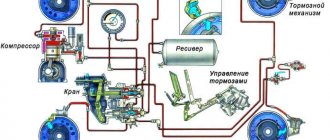
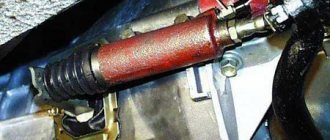
How does a hydraulic clutch drive work?
As for the hydraulic clutch drive, its design has a more complex design. Just like a mechanical drive, it contains a release bearing, a fork, and a pedal, however, instead of a torso, such a drive has a hydraulic line. In fact, such a line resembles the circuit of the brake system and consists of a tube containing the brake fluid, a master cylinder with a rod mounted on the pedal block and a working cylinder located on the drive lever and mounted on the clutch housing. Brake fluid is supplied to the clutch hydraulic system from a reservoir, which can be located directly on the working cylinder or separately from it. In some cars, the brake system reservoir can simultaneously be connected to the hydraulic clutch drive system. As for the principle of operation, when the driver presses the clutch pedal, force is transmitted through the rod to the master cylinder, and then, due to the incompressible property of the fluid, the working cylinder and, accordingly, the release bearing drive lever are actuated. As you can see, the essence is the same as in a mechanical drive, only instead of a cable, the transmission of movement is carried out by the liquid located in the tube. Servicing such a drive is very similar to servicing the brake system; there is also a special valve through which air bubbles are removed from the system.
Problems when paying with bank cards
Sometimes difficulties may arise when paying with Visa/MasterCard bank cards. The most common of them:
- There is a restriction on the card for paying for online purchases
- A plastic card is not intended for making payments online.
- The plastic card is not activated for making payments online.
- There are not enough funds on the plastic card.
In order to solve these problems, you need to call or write to the technical support of the bank where you are served. Bank specialists will help you resolve them and make payments.
That's basically it. The entire process of paying for a book in PDF format on car repair on our website takes 1-2 minutes.
If you still have any questions, you can ask them using the feedback form, or write us an email at [email protected]
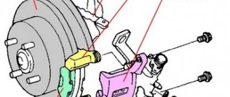
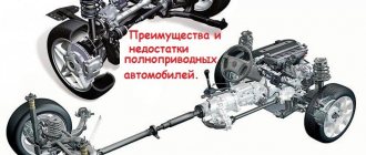
Clutch - purpose and general structure
The clutch serves to briefly disconnect the engine from the transmission and smoothly connect them.
The clutch consists of a pressure (drive) disk, a driven disk, a release bearing and a release drive.
The clutch release drive can be hydraulic or cable. In both cases, it is designed to transmit force from the clutch pedal to the release bearing.
The pressure (drive) disk is mounted on the flywheel. The clutch driven disc is located between the pressure plate and the flywheel. The driven disk is connected to the input shaft of the gearbox by a splined gear.