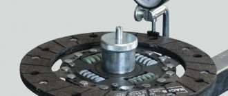
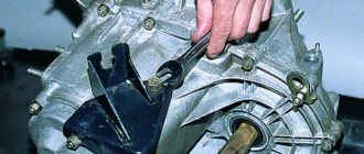
The most common electrical faults in Japanese cars
Over 10 years of work, the specialists of the Start-Motors auto repair shop have accumulated impressive experience in working with electrical equipment of both European and Japanese foreign cars.
The number of Japanese cars is not decreasing, but increasing every year. The attitude towards them is only good.
Basic qualities
1. Reliability
2. Maintainability
3. Inexpensive to operate
4. Common parts
5. Easy controls
6. The availability of a variety of additional equipment is often decisive when choosing a car.
Electrical equipment malfunctions and ways to eliminate them
External signs of electrical wiring malfunction are
Damage to electrical wiring and its elements can occur due to careless or careless handling, as a result of poor quality installation work, or physical wear and tear of wires and cables.
When maintaining internal electrical wiring, check Loose and loose wires and cables are tightened and securely fastened. If damaged rollers, insulators, insulating tubes, porcelain funnels and bushings are found, they are immediately replaced with others. Damaged sections of wiring are replaced with new ones. If the insulation is damaged! wires, it is allowed to isolate the damaged section of the wiring with adhesive insulating tape or a tube made of insulating material.
When renovating a room, it is not allowed to cover the wiring with lime, whitewash or paint over it, since water and paint solvents coming into contact with the wires will deteriorate their insulation, which can lead to a short circuit. Water penetrates cracks, is absorbed into hygroscopic materials, mixes with dirt, dissolves acids and alkalis, forming electrolytes. The latter destroy not only insulating materials, but also metals.
It is not allowed to cover wires with carpets, curtains, curtains or other flammable materials. Do not hang wires on nails or pull them back with wire or rope.
Electrical wiring and its elements are periodically inspected and checked. The number of periodic inspections of electrical wiring depends on its design and characteristics of the room. Any malfunctions, defects, or damages identified during inspection are corrected immediately.
Electrical installation devices
Electrical installation devices include:
sockets, switches, plugs, sockets, fuses, etc.
Malfunctions of electrical installation devices.
A typical malfunction of switches is mechanical jamming of the lever or key. When inspecting the switch, broken contact springs, burnt contact plates, broken plastic parts, and cracks in the bases and covers may be found. As a rule, such switches cannot be repaired and are replaced with new ones.
In plug sockets, over time, the springs that compress the contact sockets weaken, as a result of which the plug connection heats up, the contacts become covered with soot and melt. For reliable operation of the plug connection, it is necessary to compress or replace the springs and ensure contact in which the pins of the plugs are held tightly in the sockets of the socket. If there are no spare compression springs, or if there are cracks or chips in the base and cover, the sockets must be replaced.
If you pull the plug from the hidden socket, it may fall out of the box along with the wires. You can insert it back only after first disconnecting the power supply. When securing the socket in the box, you must ensure that the wires do not get caught under the spacer tabs. The screws for securing the legs are screwed in alternately and evenly.
Using tees. Sometimes several powerful electrical appliances are connected to one outlet through a tee-splitter. This is not recommended, since a large load on the wires leading to the socket leads to overheating of the latter and rapid drying of the insulation.
Incandescent lamps
The most common malfunction of the lighting network is a burnt out light bulb. To test an incandescent lamp, you must use a known-good lamp. If such a replacement does not give a positive result, the reason should be sought in the cartridge. It is necessary to check whether the base is in contact with the central contact. If necessary, you need to bend it a little. If the base-socket contact is poor, the lamp base can be welded to the socket, causing overheating of the lamp socket, lamp and supply wires. If there are mechanical breakdowns of the contact posts, burnt plastic cases, cracks or chips, the cartridge must be replaced with a known good one.
Incandescent lamps often do not turn out of the socket The use of great force usually leads to tearing off the base. In this case, it is necessary to turn off the power supply by unscrewing the safety plugs or turning off the circuit breakers. Then, carefully rotating the lamp bulb, tear off the wires on which it hangs. Use pliers to turn out the lamp base remaining in the socket. In cases where it is not possible to unscrew the base, the cartridge is disassembled.
When reloading a cartridge, it is necessary to carefully terminate the wires. After stripping the insulation, the stranded wire is twisted so that there are no wires sticking out to the sides. Then a ring is formed using round pliers; it is advisable to tin the ring. The place where the insulation is stripped and the wire up to the ring is wrapped with insulating tape. Proper recharging is also necessary when connecting wires and cords to household electrical appliances. In the case of careless termination of the wires, a short circuit may occur between the protruding conductors, or it is enough for one wire from the ring to touch the outer parts of the fittings so that when touching them a person will become energized.
Luminaires with fluorescent lamps
Fluorescent lamps are a complex device with many structural elements and a large number of contacts. Therefore, problems with the operation of lamps can be very diverse. Possible malfunctions in the operation of fluorescent lamps and methods for eliminating them are given in table. 38.
Fluorescent lamps are removed from their sockets with great care so as not to damage the base or break the glass of the lamp, since the lamp contains mercury vapor, which is very toxic.
When operating fluorescent lamps, you need to know that the nature of the gas discharge is largely determined by the pressure of the gas or vapor in which the discharge occurs. As the temperature drops, the vapor pressure in the lamp drops and the process of ignition and combustion of the lamp deteriorates, and at temperatures below 5°C the lamp does not ignite at all.
The optimal operating temperature for fluorescent lamps is 20-25″ C.
Maintenance of lighting fixtures is usually carried out simultaneously with maintenance of electrical wiring.
Table 38. Possible malfunctions in luminaires with fluorescent lamps, causes and methods for eliminating them
| Malfunction | Cause | Fault detection method | Troubleshooting method |
| 1 | 2 | 3 | 4 |
| The lamp does not light up The lamp does not light up There is no glow at the ends of the lamp | There is no voltage on the lamp socket on the mains side, the mains voltage is low Poor contact between the lamp pins and the socket contacts or between the starter pins and the starter holder contacts Lamp malfunction, broken or burnt filaments Starter malfunction - the starter does not close the filament circuit of the lamp cathodes Malfunction in the electrical circuit of the lamp Malfunction of ballasts (ballast control equipment) | Check with an indicator or voltmeter the presence and magnitude of voltage Move the lamp and starter in their holders to the sides Install a known-good lamp. There is no light in the starter. Check all connections in the diagram If wire breaks, contact connections are broken and | Check the power supply and ensure normal voltage Ensure good contact Replace the lamp Replace the starter Eliminate detected faults Replace ballasts |
| The lamp does not light up. The ends of the lamp glow The lamp flashes but does not light up, there is a glow at one end The lamp does not blink and does not light up, there is a glow at both ends of the electrode The lamp blinks and does not light up When the lamp is turned on, an orange color is observed at its ends. | Starter malfunction Errors in the circuit; short circuit in the circuit or socket that short-circuits the lamp; shorting the terminals of the lamp electrodes Error in the circuit, starter malfunction (breakdown of the capacitor to suppress radio interference or sticking of the starter contacts) The starter is faulty; errors in the circuit; low mains voltage; loss of lamp electrode emission The lamp is faulty, air has entered the lamp | no errors were found in the circuit, then the ballast is obviously faulty. Remove the starter, the glow at both ends will stop. The lamp is removed and inserted into the lamp, swapping the ends of the lamp. If a previously non-luminous electrode glows, then the lamp is working. There is no glow at the same end of the lamp. Install a working starter. Check the network voltage with a voltmeter | Replace starter Check if there is a short circuit in the cartridge on the side of the non-luminous electrode. If no short circuit is detected, check the wiring diagram Replace the lamp Replace starter Replace starter; replace the lamp; ensure normal mains voltage Replace the lamp |
| glow, after a while the glow disappears and the lamp does not light up. The lamp alternately lights up and goes out. When the lamp is turned on, the spirals of its electrodes burn out The lamp lights up, but after a few hours of operation blackening of its ends appears The lamp lights up, when it burns, the discharge cord begins to rotate and moving spiral and serpentine stripes appear | Lamp failure Malfunction of the ballast (insulation or turn-to-turn short circuit in the winding is broken), there is a short circuit to the housing in the electrical circuit Short circuit to the luminaire body in the electrical circuit Faulty ballast The lamp is faulty; strong fluctuations in network voltage, loose contacts; the lamp covers the magnetic field lines of the ballast leakage | Carry out a thorough inspection of the electrical circuit; check the insulation of the wiring in relation to the body of the lamp Check the insulation of the wiring Using an ammeter, check the value of the starting and operating current | Replace the lamp, if the blinking continues, then replace the starter. Replace the ballast, eliminate the short circuit. Eliminate short circuit to the housing. If the current exceeds normal values, replace the ballast. Replace the lamp; check the network voltage; check contact connections; replace ballast |
Maintenance work on luminaires includes
- checking the fastening, condition of hooks and brackets;
- checking the compliance of the power of installed lamps;
- checking the condition of the insulation of wires at the places where they enter the lamps and at the places where they are terminated;
- removing dust and dirt from fixtures;
- removing glass and electric lamps and washing them;
- replacement of glass with cracks and chips;
- removing the cartridge body, cleaning contacts, tightening loose clamps;
- inspection of the condition of lighting fixtures and replacement of faulty parts;
- painting metal parts of fittings.
All types of work are carried out with the voltage turned off.
Connecting cords and plugs
Cord faults. Most often, during operation, the connecting cord of the electrical receiver wears out and is damaged. The main malfunctions of connecting cords are kink or breakage of conductor strands, as well as insulation failure, which can result in a short circuit. Therefore, before each turn on, check the condition of the insulation and braiding of the cord, especially at the points where it enters the plug, plug connector or device. The cord or flexible wire should not be twisted, no knots, twists, etc. should form on it. In such places, the cord insulation quickly wears out and the current-carrying conductors are exposed. Exposed areas of the cord are carefully insulated. If there are a lot of bare places, then the cord is completely replaced.
Breakage of current-carrying wires along the length is eliminated by recharging the cord. To do this, the cord at the point where the wire is broken or broken is cut at intervals of 10-20 mm, the wires are stripped and connected. Each core is insulated separately, and then a general insulation is applied. If the cord is damaged at the point of entry into the electrical appliance, the end of the cord with slip rings is shortened by 60-80 mm, the ends of the cord are stripped of insulation to a length of 20-25 mm and slip rings are made, which are then preferably tinned. The ends of the cord with slip rings are covered over a length of 10 mm with insulating tape so that the ring protrudes from the insulation, after which the cord is connected to the device.
Typical plug faults are
- breakage (break) of the cord when entering the plug body;
- unreliable contact of the terminated wire with the contact pin;
- oxidation and corrosion of the contact pin.
Apartment shields
When inspecting apartment panels, it is necessary to pay attention to the condition of the contacts at the places where the wires are connected. An unreliable connection leads to heating and burning of the contact, destruction of insulation and sparking. Such contacts are cleaned of soot and tightened tightly.
Circuit breakers, PAIRS and fuse links must match the loads and cross-sections of wires and cables. Protection devices with damaged housings cannot be repaired and must be replaced with new ones.
Apartment panels with cabinets must have working locks and reliable door seals. It is not permitted to store foreign objects in these cabinets.
Electric meters must not have damage to the housing, sight glasses, terminal covers, etc. Two seals are installed on the meter: one on the screws securing the meter casing, the other on the terminal cover when installing or replacing the meter.
The serviceability of the counter can be determined by the rotation of its disk. When turned off, the meter disk should stop after completing no more than one revolution. If the disk continues to rotate after turning off all pantographs, then the meter should be removed and rechecked at the relevant organizations. If the meter turns out to be in good working order, but the disk continues to rotate when the load is turned off, this means that the insulation of the electrical conductor is damaged and there is a significant current leakage. In this case, it is necessary to stop using electricity, determine the location of the damage to the wiring and eliminate power leakage.
The operation of electrical wiring with increased leakage currents is dangerous from a fire point of view (the building may catch fire), and from the point of view of electrical safety, since the damp walls of the building may be energized.
You can determine the correctness of the meter reading at home. To do this, turn off all lamps, heating devices and other consumers. For 10-15 minutes, turn on one consumer with a known power, for example an electric lamp, and determine the actual electricity consumption, which should coincide with the meter readings, taking into account the latter’s error.
External signs of a meter overload are a specific smell of burnt insulation, abnormal humming of the meter, and yellowing of the glass viewing window.
The buzzing of the meter, if it is not accompanied by self-propelling, is not a sign of its malfunction.
Triggering of protective equipment occurs due to short circuits in electrical wiring and current collectors or due to overload.
To quickly and accurately determine the location of the fault, they use the method of sequential connection of loads. To do this, turn off all electrical receivers. Replace the burnt plug, turn on the STEAM or circuit breaker. If the protection is triggered again immediately, the most likely location of the short circuit is the electrical wiring or plug socket. If the protection does not operate immediately, then turn on the lighting devices one by one, then other current collectors until a short circuit occurs. In lamps, damage most often occurs in the sockets. In the case when the protection is triggered some time after the load is turned on, it is necessary to turn off some of the electrical receivers (reduce the load), since in this case the network load exceeds the protection trip current.
You cannot install wire jumpers (bugs) instead of the factory plug, as they do not burn out even at high currents, as a result of which the insulation may catch fire and a fire may occur.
Before connecting any household electrical appliance to the network, make sure Do not connect devices to the network that do not match the network voltage. Before connecting a new device to the network, you should pay attention to the current or power they consume and calculate whether the fuses and wiring will withstand the inclusion of these devices.
Preventative testing of electrical wiring
During testing, the integrity of the cores and the correct phasing are checked - the phase connection to the switch and to the central contact of the cartridge.
At least once every three years, the insulation of the electrical wiring The lowest insulation resistance is 0.5 MOhm. If the resistance is less than 0.5 MOhm, then it is necessary to determine the cause and correct the damaged part of the wiring.
Why does the electrical equipment of a Japanese car malfunction?
Most defects appear due to improper operation of the vehicle or unprofessional intervention in the operation of the units. A few recommendations for taking care of the electrical equipment of a Japanese car.
· The terminals on the battery need to be kept clean, any oxidation should be removed, and a little bit of engine oil can be easily applied. It's not hard to make contact. This extends the life of the generator.
· It is advisable to change spark plugs, especially if you know that gasoline is not of the best quality.
· You should wash the engine in consultation with a specialist. Stupid engine washing leads to repair of the ignition system.
· Not every car service center will install a security alarm correctly or replace the audio system properly; this is fraught with a variety of breakdowns. Difficulties may arise with the transponder central locking system or immobilizer. Someone decides to install a powerful car radio and leaves the old electrical wiring, and this is unacceptable.
AUTOFIZIK.RU / auto repair
Most often, during everyday use of a car, electrical equipment malfunctions occur. For objective reasons, repairs of electrical equipment must be carried out by qualified car service specialists.
Warning Failure of electrical equipment (short circuit) can lead to ignition of electrical wiring and fire. If a fuse has blown, replace it; if the same fuse blows again, it serves as a signal to immediately contact a service center. Warning It is strictly forbidden to replace a blown fuse with another one with a higher “value” or “bug”. To make troubleshooting easier, purchase a wiring diagram for your vehicle. If an electrical equipment malfunction occurs before you have time to buy an electrical circuit, you can fix minor problems yourself, which this section will help you with.
Types and arrangement of lamps
Mounting blocks On cars of the VAZ-2109 family, two mounting blocks are used - the old 17.3722 and since 1998 the new 2114-3722010-60. The main difference is the use of a new type of fuses: blade fuses instead of cylindrical ones and new compact relays. Mounting block type 17.3722:
1. Relay for turning on headlight cleaners (K6). 2. Rear window washer time relay (K1). 3. Relay-breaker for direction indicators and hazard warning lights (K2). 4. Windshield wiper relay (K3). 5. Contact jumpers in place of the relay for monitoring the health of the lamps. 6. Relay for turning on the heated rear window (K10). 7. Spare fuse. 8. Headlight high beam relay (K5). 9. Relay for low beam headlights (K11). 10. Fuse. 11. Relay for turning on the electric motor of the engine cooling fan (K9). 12. Relay for turning on the sound signal (K8).
Mounting block type 2114–3722010–60:
K1. Relay for turning on headlight cleaners. K2. Relay-breaker for direction indicators and hazard warning lights. K3. Windshield wiper relay. K4. Relay for monitoring the health of lamps. K5. Power window relay. K6. Relay for turning on sound signals. K7. Relay for turning on the heated rear window. K8. Headlight high beam relay. K9. Relay for low beam headlights. F1–F16. Fuses. F17–F20. Spare fuses.
Circuits protected by fuses
Specialized relays
Electrical diagrams To carry out repair work in the previous sections, you can use the explanatory electrical diagrams given below.
Contactless ignition system diagram:
1. Contactless sensor. 2. Ignition distributor sensor. 3. Spark plugs. 4. Switch. 5. Ignition coil. 6. Mounting block. 7. Ignition relay. 8. Ignition switch.
Carburetor solenoid valve control system:
1. Carburetor limit switch. 2. Carburetor solenoid valve. 3. Mounting block. 4. Ignition switch. 5. Ignition relay. 6. Control unit. 7. Ignition coil. A. To terminal “30” of the generator. B. Numbering of plugs in the control unit.
Generator connection diagram:
1. Generator. 2. Negative valve. 3. Additional diode. 4. Positive valve. 5. Battery discharge warning lamp. 6. Instrument cluster. 7. Voltmeter. 8. Mounting block. 9. Additional resistors of 100 Ohm, 2 W. 10. Ignition relay. 11. Ignition switch. 12. Rechargeable battery. 13. Capacitor. 14. Rotor winding. 15. Voltage regulator.
Connection diagram for the electric motor of the engine cooling system fan on vehicles with a mounting block type 17.3722:
1. Fan motor. 2. Motor start sensor. 3. Mounting block. 4. Ignition switch. K9. Fan motor relay. A. To terminal “30” of the generator.
Starter connection diagram:
1. Starter enable relay. 2. Mounting block. 3. Ignition switch. 4. Generator. 5. Rechargeable battery. 6. Starter. A. Pull-in winding. b. Holding winding.
Connection diagram for the electric motor of the engine cooling system fan on vehicles with a mounting block type 2114–3722010–60:
1. Fan motor. 2. Sensor 66.3710 for turning on the electric motor. 3. Mounting block. A. To terminal “30” of the generator.
TOYOTA is the most common Japanese car in Russia
It is the easiest to diagnose and easy to maintain electrical wiring. It has the easiest repairs, the market is saturated with spare parts, getting them is not a problem. These are original new ones from Japan and analog ones from China and Taiwan. There are a lot of contract (used) spare parts on the market from Japan without mileage in Russia.
List of the most common weak machine components
· The battery charging system on Toyota trucks and minibuses with a diesel engine is a problem with undercharging;
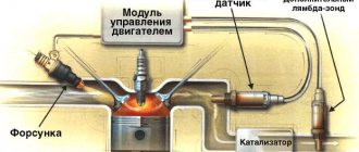
· Lambda probe (oxygen sensor that regulates the fuel-air mixture) often fails;
· Temperature sensor of the spark plug control unit and thin conductors;
· Windshield wipers, mostly on TOYOTA COROLLA, with a vulnerable mechanical drive, mainly due to the relay controller;
· The window lift mechanism leaves much to be desired for greater reliability;
· Radiator installed on the air conditioner of SUVs and minibuses with an unreliable fan;
· Throttle valve mechanism with unreliable positioner, especially on older engines with high mileage;
· The idle air control of older models often fails;
· Mass air flow sensor of cars of old year of manufacture (loss of power, vulnerability to pollution);
· Electrical wiring located in the lower part in front of the engine compartment.
Diagnosis of car electrical faults
There are several general methods for diagnosing automotive electrical faults, which are relatively simple and do not require special skills.
- If any electrical appliance in the car or a group of electrical consumers fails, first check the fuse responsible for the failed electrical equipment. Usually on the cover of the fuse box there are instructions indicating which fuses are responsible for which group of devices.
- Make sure that live wiring accessible for inspection is not damaged. If possible, manually inspect the entire length of the wire for insulation damage or melted areas.
- Disconnect, one by one, all the circuits in the area leading to the failed equipment and carefully inspect the contacts for mechanical damage or oxides.
This algorithm often allows you to identify the source of the problem and quickly eliminate the fault in your auto electrics.
We will also look at several typical situations that may be the result of failed electronics.
- Troubles the gasoline engine. This means that the fuel-air mixture does not ignite in one of the cylinders. In most cases, this is due to a lack of spark at the plug. First you need to find out which cylinder is not working. To do this, remove the high-voltage wire from each cylinder one by one (first put on dielectric gloves). The cylinder that does not work is the one from which, when the high-voltage wire is disconnected, there is no change in the operation of the motor. If necessary, replace the spark plug or wire.
- The battery charging indicator lights up. First, inspect the wiring from the generator to the battery. Make sure the drive belt is tight and the alternator pulley is turning. On older gasoline vehicles without an ECU, try disconnecting the negative terminal from the battery with the engine running. If the engine stalls, it means the generator itself is faulty.
- The starter does not show “signs of life” after turning the key, although the rest of the car’s electrical equipment is working properly. Engage neutral gear (or park mode) and try to manually briefly short-circuit the two positive terminals on the starter using a screwdriver or any other metal object (with a thin wire - to the solenoid relay; with a thick wire - to the electric motor itself). If the starter comes to life, then the problem is in the control circuit. After closing the contacts there is no reaction? This means the starter is faulty.
If the above steps do not produce results, it is better to seek help from a qualified auto electrician. The electronics of a modern car are quite complex, and without proper knowledge it is not worth carrying out more complex diagnostic procedures yourself, as you can damage expensive electrical equipment.
NISSAN is the next reliable Japanese car after TOYOTA
For cars of this brand, typical faults are most often found in the following places:
· Controlling the radiator fan motor control – the problem is in the sensor;
· The mass air flow sensor or flow meter is sensitive to even minor pressure or slight mechanical damage and immediately fails;
· Idle air control (frequent breaks and short circuits of the valve, sometimes the IACV control driver fails);
· Ignition distributor cover (distributor) – rapid wear of structural elements;
· Fuel pump (sensitivity to contamination of the filter and level sensor);
· Connecting wires, terminals and fuse blocks located under the hood;
· Electronic control units (ECUs) fail for unexplained reasons;
· Diesel NISSAN with glow plugs has an unreliable pre-heater system;
· Dashboard (frequent problems with backlighting, inconsistencies in readings);
· Electric throttle drive of new cars with a weak control system.
MITSUBISHI is a middling car and the most desirable car in Russia
The most common machine problems:
· Fuse blocks hidden under the hood - contacts often disappear, wires bend;
· Underhood electrical wiring, hidden in bundles behind the fender liners and hidden in the sills - frequent wear, poor insulation;
· The idle speed control often comes out;
· Wiring in connectors from the rack to the door: frequent creases, poor insulation, frequent failure of the lock and lock;
· The high-pressure motor designed for headlight washers often fails;
· Electronic control units (ECU) of the preheater: depressurization, failure of the transfer pump and circulation disturbance or failure of the thermobimetallic sensor;
· Engine ECU failure for no apparent reason;
· Climate control: frequent malfunctions of the stove, failure of the regulator when switching from “heat to cold”;
· Automatic transmission – sensors coming out, poor wiring insulation;
· ABS sensors fail, which often affects SUVs;
· Electrical wiring located in the rear lights of SUVs;
· Ignition distributor, coil fails.