The booster pump is designed to overcome the resistance of the filters. Regulates uniform fuel supply to the main pump. Thus, the fuel priming pump supplies fuel from the tractor tank to the fuel pump.
Booster pump and operation process
Let's take a closer look at the purpose and structure of this spare part. The piston-type booster pump is attached to the cast iron fuel pump housing. A metal piston is installed here.
The element is driven by a special steel pusher. Next, the spring presses the pusher against the shaft. The rod then moves in the sleeve.
In addition to the listed elements, the booster pump has in its design:
- Handle with piston;
- Valve and its spring;
- Gasket and O-ring;
- Cork, washer, bracket and other parts.
study in more detail what the fuel priming pump in this figure. The booster pump is responsible for uniform fuel supply. To do this, the pusher comes off the eccentric.
Gradually the piston moves back under the action of the spring. The intake valve opens and the exhaust valve closes. Fuel is sucked through a special channel into the cavity above the cleaning filter and piston.
Booster pump - repair tips
The fuel priming pump has a reliable device. MTZ spare parts of this class are certified. However, over time the pump fails. Therefore, repairs have to be carried out. Repairing the booster pump is not difficult.
The main thing is to know the reason for the element failure. According to experts, the main problem with the part is the ingress of excess oxygen. That is, sometimes the booster pump has a pressure higher than 0.15-0.17 MPa.
It is for this reason that the piston becomes difficult to move and the fuel supply is interrupted. This may cause the tractor engine to fail to start. In some cases, the piston stops moving altogether.
All this will inevitably lead to replacing the pump. We recommend periodically inspecting the condition of MTZ spare parts. If problems are detected with the pumps, we recommend doing the following.
Use a manual priming pump to remove air from the system. First move the piston rod handle down, then up. Before doing this, do not forget to open the filter valve (we mean a fine filter).
Afterwards we carefully pump the fuel. As soon as fuel starts to come out of the drain tube without any air bubbles, stop pumping. Next, tighten the filter valve and attach the handle to the shank of the lid. Don’t forget about this important nuance after pumping. Otherwise, the booster pump will leak air during operation.
This means that soon you will have to pump again. A fuel priming or simply priming pump does not require special maintenance. The main thing is to prevent air from entering the working systems.
You can order MTZ spare parts at excellent prices on our website. We offer delivery, guarantee and free consultation to every client.
Source: mtzrostov.ru
Boost pump for a summer residence: what are they?
This is a small device that increases existing low blood pressure. That is, they cannot create it from scratch. This device crashes into an existing water supply system and pumps up water, raising the pressure by 1-3 atm. There are several types of pressure booster pumps:
- By type of cooling: with a dry rotor - they have a higher efficiency, but are noisier and have larger sizes;
- with a wet rotor - the noise level is low, the dimensions are small, but not very effective, although they can cope 100% with increasing pressure in the country water supply (and not only).
- manual activation - when you need to increase the pressure, turn it on, if not necessary, turn it off; not very convenient: you need to make sure that the pump does not overheat;
- horizontally;
- single-stage - have one pumping speed;
- in-line - compact but low-performance models built into the supply pipeline;
You can read here how to bring water into a house from a well, and you can read about organizing automatic watering here.
How to choose
To avoid too much confusion, a booster pump for water supply in a country house is usually taken in-line (built-in) with a wet rotor. This is the best option for a summer residence: little noise, ease of installation.
The type of installation - vertical or horizontal - depends on the place in which you will install it. Regarding speeds, multi-stage adjustment is, of course, better, but such pumps cost a lot, so they are rarely installed in country water supply systems.
You can also pay attention to the material of the case. It can be made of cast iron or stainless steel. Stainless steel is naturally better, but also more expensive. You need to pay attention to the material from which the pump impeller is made. In the cheapest models it can be made of plastic, in more expensive ones it can be made of bronze or brass.
Design features of water pumps and their selection
The operating principle of the equipment in question is to create sufficient pressure in the system depending on the current indicator. Key Features:
- The device must be installed exclusively in a horizontal position. In such a case, you can eliminate the possibility of damage to structural elements and also ensure quiet operation.
- Many versions operate automatically using electricity. The required pressure is created when the rotor or other structural elements rotate.
- Manually operated versions are also available for sale. Such design options are much cheaper, but they do not provide the required degree of automation.
The selection of pumps under consideration should be given a lot of attention. Main criteria:
- Performance is considered the main selection criterion. The device can pass a certain amount of liquid over a certain period. As a rule, manufacturers indicate a performance indicator.
- Power is also taken into account when choosing the most suitable booster pump. An electric motor is characterized by power; as it increases, the device becomes more productive, but electricity costs also increase significantly.
- The size of the device also matters. This is due to the fact that a device that is too large will be difficult to install and will require a special room. In addition, the weight of the device can be considered an important selection criterion.
- The nature of the adjustment. Based on this feature, devices with manual and automatic adjustment can be distinguished. With manual control, you have to constantly monitor the water level, as well as constantly turn the device on and off. It is worth considering that operating for too long can lead to increased temperatures and overheating. Automatic ones can operate from installed sensors.
- The noise level is important when installing the device in a home. This indicator may depend on a variety of factors. An example is that the design with a dry rotor causes noise during operation. Over time, due to wear and tear of the structure, the noise level can increase significantly.
- The materials used in the manufacture of the device must also be taken into account. Budget versions are often made using plastic, while professional ones for industrial use are made from metal with high corrosion resistance. However, when using plastic, manufacturers significantly reduce the cost of the product; in addition, the material does not react to environmental influences.
An important selection criterion is cost. It depends on the popularity of the brand, as well as the design features of the device. It is worth considering that products from a well-known manufacturer are much more expensive, but the technical characteristics may not be much higher.
The main classification can be called the type of rotor:
- Wet. In this case, the device is cooled using water. This design option is characterized by silent operation, but the design is more demanding on the quality of the pumped water. Only with proper and timely maintenance can conditions for long-term operation of the device be ensured.
- Dry. The design with a dry rotor is characterized by the fact that cooling occurs due to the impeller. This design option is characterized by reliability and long service life, but they are a little noisy during operation. Today, such water pumps are very popular.
It is worth considering that only with proper installation can the device last for a long period. In addition, timely maintenance is required.
Technical characteristics and their meaning
First of all, you need to remember that the pump runs on electricity and needs a normal power supply. They are mostly voltage hungry. If, suddenly, the selected booster pump does not produce the required pressure, check the voltage. Perhaps it is low and the required operating power is simply not achieved.
The main technical characteristics that determine whether the pump that increases the pressure in the water supply system at the dacha will cope with the task is the maximum operating pressure . This is the value that the equipment can output.
The following characteristics are also important:
- Maximum feed. Shows how much water the pump can pump per unit of time. It is measured in liters per minute (l/min) or cubic meters per hour (mcub/hour). To make comparison more convenient, convert l/min to liters per hour - multiply the figure by 60, divide the resulting liters by 1000 and get cubic meters per hour. For example, we convert 30 l/min to cubic meters/hour: 30*60=1800 liters per hour, 1800/1000=1.8 cubic meters/hour.
- Maximum pressure . This is the amount by which the booster pump can raise water relative to its installation location. This is important if the cottage has two floors or more, and the pump is installed, say, on the technical floor or basement.
Please note that the maximum values are usually indicated. To find out the real indicators, divide the stated parameters by 2. Then you definitely won’t go wrong.
Another important thing is at what flow value the automatic booster pump for the dacha is turned on. The values may be different: 0.12 l/min and 0.3 l/min. This figure determines whether the pump will turn on when, for example, the toilet tank is filled, or whether it will start working only after the tap in the shower opens.
A few words about what modes the pump should operate to increase the pressure in the water supply system at the dacha. It is best to take those models that can work both manually and automatically. Here's why: not all analysis points create the flow required for automatic activation. If the device only has an automatic mode, you will not help the trouble. But if you can switch it to manual, turn it on before use and enjoy normal pressure. Just remember to turn it off.
The next parameter is maximum and nominal power, measured in watts (W). Shows how efficient the motor drives the impeller. In principle, the more powerful the pump, the more pressure it can provide, but much still depends on the design and materials used.
Temperature of the working environment. Measured in degrees. Everything is more or less clear here. There are pumps to increase pressure only for cold water, and there are pumps for hot water. This is what this indicator reflects.
Connecting dimensions are also important . The installation of a booster pump takes place in a cut - a piece of pipe is cut out, and a device is installed in this place using fittings. The size of the connection nuts should ideally correspond to the diameter of the pipe.
About the installation of a country water supply system (by area) - selection of pipes, development of a diagram and connection - read here.
Installing a pump that increases water pressure
The installation location of the pumps depends on the specific situation. For normal operation of the faucet and shower, it is enough to install a pump at the outlet of the storage tank, if we are talking about such a system. If you want to install a boiler or a washing machine at your dacha, other devices that require pressure will most likely have to be placed in front of them. With sufficient power (with sufficient flow), one pump can be enough for two devices. Only then should you think through the scheme accordingly.
In any case, when developing the circuit, consider the possibility of removing or bypassing the pump. This is done using a bypass (there should be a shut-off valve in the bypass).
Installing several low-power booster pumps is not always the best idea. In this case, it may be worth considering more powerful and efficient models that can stabilize pressure at significant flow rates. Some of them even provide lifting of water from a well or reservoir, replacing, in a sense, a pumping station.
Read here how to avoid freezing the water supply at your dacha.
Pressure booster pump station
This solution is very convenient, but not very cheap, although there are inexpensive models (for example, Gilex Jumbo installations cost from $130). These installations can lift water from a well or borehole, but the suction hose can also be lowered into a tank. Then the storage tank can be placed anywhere, not necessarily at the top.
Their advantage is that the pressure is maintained constantly, without human intervention (as long as there is electricity). The main thing is to choose the right parameters. They can even be used to increase pressure when connected to a centralized water supply. If you have this option at your dacha:
- water is supplied through pipes, but its pressure is not enough even for a shower, not to mention other needs,
- The supply goes by the clock, and you cannot always be at the dacha at this time, and accordingly, everything remains without watering, and then there is no question of such a luxury as a shower.
Everything can be fixed by installing a large tank (1000 liters) and a pumping station. You will have a supply of water and a shower whenever you want. Such a container may not be enough for watering, but no one bothers to install a larger one or a slightly smaller one. Read about choosing and installing a pumping station here.
Source: stroychik.ru
Diesel engine booster pump for fuel injection pump
So, a low pressure fuel pump (LPFP) is needed to pass diesel fuel through the filters under low pressure and then supply fuel to the fuel injection pump. In this case, there are two operating modes of the device. The tractor's feed pump supplies fuel from the tank to the fuel pump under pressure. This is necessary to overcome the hydraulic resistance of the filter and pipelines, as well. The first mode is the so-called preparatory mode, while the second mode is working.
As for the preparatory mode, at this moment the piston in the pump moves upward, and in parallel, the effect of the eccentric is noted, which compresses the spring. As a result, fuel begins to move in the chambers and also passes between the filters. The operating mode of the low-pressure pump is the reverse movement of the piston (the piston moves viz).
It is worth noting that the low pressure pump pumps slightly more fuel than the engine needs for smooth operation. Such pumping “with a reserve” allows you to maintain optimal pressure in the power system, avoiding increased loads.
Manual booster pump
To fill the fuel system with fuel when the diesel engine is not running and remove air from it, a manual booster pump, also of the piston type, is installed on the booster pump.
- cylinder screwed into the housing above the intake valve
- main booster pump
- piston with rod
- handle screwed onto the cylinder cover.
This pump uses the inlet and discharge valves of the main booster pump.
- Before filling the system with fuel, you must:
- open the valve on the fine filter
- Unscrew the handle from the pump cylinder cover
- Using the handle, move the piston in the cylinder and pump fuel into the system until a stream of fuel without air bubbles appears from the drain tube.
After pumping the system, the valve on the filter must be closed, and the piston handle of the hand pump must be screwed onto the cylinder cover.
The device of the booster pump and various types of low-pressure pumps
If we talk about design, the low pressure fuel pump has the following components:
- Drive shaft
- Rotor with blades
- Stator
- Distribution disk
- Drive gear regulator
- Couplings
The principle of operation is that the rotor begins to move first, as a result of which its blades move closer to the stator. As a result, under the influence of centrifugal force, “chambers” and a certain voltage are created. Then the fuel flows from the chambers to the fuel injection pump. To supply fuel, channels are made in the distribution disk. If the pressure exceeds the norm, part of the fuel is redirected to the pressure reducing valve.
Installing a fuel booster pump on a Nissan Patrol Zd30
Installing a fuel booster pump
for Nissan Patrol ZD30.
Given that the booster pump and the high pressure pump are connected, a fuel drain choke is provided to maintain the required conditions. The specified throttle is a jet that is screwed into the injection pump.
This solution allows you to maintain the desired conditions in the chambers, while taking into account the dependence on the speed at which the drive shaft moves. This scheme is well suited for diesel engines, but there are other types of booster pumps.
Types of low pressure fuel pumps
Let's start with the fact that a low-pressure fuel pump is installed on any car, gasoline (carburetor, injector), and on many diesel ones, but not on all. This device “pulls” fuel from the fuel tank, after which the fuel passes through filters, enters the metering systems and is supplied to the engine.
In this case, booster pumps are mechanical and electric. What is a fuel injection pump for a diesel engine? A fuel injection pump for a diesel engine and a booster pump. How to bleed the diesel engine power system to remove air. Various methods of de-airing, removing air from the filter and injection pump.... On gasoline carburetor internal combustion engines there is a mechanical pump, on injection engines there is an electric fuel pump. However, if in gasoline analogues, regardless of the type of engine, such a pump is the main one, in diesel engines the booster pump supplies fuel to the injection pump.
This solution has a number of advantages, since the device is more productive and also does not overheat from excess heat in the engine compartment. Also, before starting the engine, there is no need to pump fuel manually, since after turning the ignition key, the booster pump immediately starts working, raising the pressure in the power system.
It should also be noted that in a circuit with an electric pump, fuel constantly moves through the lines, which allows maintaining a normal temperature of the fuel and avoiding overheating.
KAMAZ engine fuel pump, turning on the pump
_________________________________________________________________________________________
Design and details of the fuel system of the Kamaz-740 engine
The fuel supply system (fuel system) of KamAZ-740 ensures fuel purification and its uniform distribution among the engine cylinders in strictly metered portions.
Kamaz-740 engines use a split-type fuel supply system, consisting of a high-pressure fuel pump, injectors, coarse and fine filters, a low-pressure fuel booster pump, low- and high-pressure fuel lines, fuel tanks, a solenoid valve and flare spark plugs for an electric torch starting device.
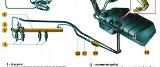
A schematic diagram of the Kamaz-740 fuel system is shown in Fig. 1. Fuel from tank 1 through a coarse filter 2 is sucked in by the fuel priming pump and through a fine filter 17 through low pressure fuel lines 3, 9, 15, 21 and supplied to the high pressure fuel pump; According to the operating order of the engine cylinders, the pump distributes fuel through high-pressure pipelines 6 to injectors 5.
Rice. 1. Diagram of the fuel system of the Kamaz-740 engine
1 – fuel tank; 2 – fuel coarse filter; 3-fuel pipe supplying the low pressure pump; 4 – fuel drainage pipe for left head injectors; 5 – nozzle; 6 – high pressure fuel pipe; 7 – low pressure fuel priming pump; 8 – manual fuel priming pump; 9 – fuel outlet pipe of the low pressure pump; 10 – high pressure fuel pump; 11 – electromagnetic valve; 12-fuel pipe to the solenoid valve; 13 – torch candle; 14 – fuel drain pipe for right-hand injectors; 15 – fuel supply pipe to the injection pump; 16 – fuel outlet pipe of the injection pump; 17 – fine fuel filter; 18 – fuel fine filter tube; 19 – tee for fastening fuel pipes; 20 – fuel drain pipe; 21 – fuel line to the coarse filter; 22 – receiving pipe with filter
Kamaz-740 injectors spray and inject fuel into the combustion chambers. Excess fuel, and along with it the air that has entered the Kamaz-740 fuel system, is discharged into the fuel tank through the bypass valve of the high-pressure fuel pump and the fine filter nozzle valve through fuel drain lines 16 and 18.
The fuel that has leaked through the gap between the nozzle body and the needle is drained into the tank through fuel drain lines 4, 14, 20.
The coarse filter (sump) Kamaz-740 (Fig. 2) pre-cleanses the fuel entering the low-pressure fuel priming pump.
Rice. 2. Coarse fuel filter Kamaz-740
1 – plug; 2 – glass; 3 – pacifier; 4 – filter mesh; 5 – reflector; 6 – distributor; 7 – bolt; 8 – flange; 9 – sealing ring; 10 – body
The coarse filter is installed on the suction line of the Kamaz-740 power system on the left side of the vehicle on the frame. Glass 2 is connected to body 10 with four bolts 7 and sealed with ring 9.
A drain plug 1 is screwed into the bottom of the cap boss. The fuel coming from the fuel tank through the supply fitting flows into the glasses.
Large particles and water collect at the bottom of the glass. From the upper part, through filter mesh 4, fuel is supplied to the fuel priming pump through the outlet fitting and fuel lines.
The Kamaz-740 fine filter (Fig. 3), which finally cleans the fuel before entering the high-pressure fuel pump, is installed at the highest point of the Kamaz-740 power system to collect and remove into the tank the air that has entered the power system along with part of the fuel through the valve - jet installed in housing 1.
Rice. 3. Fine fuel filter Kamaz-740
1 – body: 2 – bolt; 3 – sealing washer; 4 – plug; 5, 6 – sealing gaskets; .7 – filter element; 8 – cap; 9 – filter element spring; 10 – drain plug; 11 – rod
The beginning of the shift of valve-nozzle 4 (Fig. 4) occurs at a pressure in the cavity of 24.5... 44.1 kPa (0.25... 0.45 kgf/cm2), and the beginning of the fuel bypass from cavity A to cavity B - at a pressure in the cavity A 196.2... 235.3 kPa (2.0... 2.4 kgf/cm2). The valve is adjusted by selecting adjusting washers 1 inside the valve plug.
Rice. 4. Valve-nozzle for fine fuel filter KamAZ-740
1 – adjusting washer; 2 – valve plug; 3-spring; 4 – jet valve
Kamaz-740 fuel lines are divided into low pressure fuel lines of 392... 1961 kPa (4... 20 kgf/cm2) and high pressure of more than 19614 kPa (200 kgf/cm2).
The high-pressure fuel lines of the Kamaz-740 fuel system are made of steel tubes, the ends of which are made cone-shaped, pressed with union nuts through washers to the conical sockets of the fuel pump fittings and injectors. To avoid damage from vibration, the fuel lines are secured with brackets and brackets.
Fuel injection pump Kamaz-740
The Kamaz-740 high-pressure fuel pump (HFP) is designed to supply strictly dosed portions of fuel under high pressure to the engine cylinders at certain times.
Eight sections are installed in the Kamaz-740 injection pump housing (Fig. 5), each consisting of a housing 17, a sleeve 16 of a plunger 11, a rotary sleeve 10, a discharge valve 19, pressed through a sealing gasket 18 to the plunger sleeve by a fitting 20. The plunger performs a reciprocating movement under the action of the cam shaft 44 and spring 8.
Rice. 5. Fuel pump TNVD Kamaz-740
1 – body; 2, 32 – pusher rollers; 3, 31 – roller axes; 4 - roller bushing; 5 – pusher heel; 6 – cracker; 7 – pusher spring plate; 8 – pusher spring: 9,34,43,45, 51 – washers; 10 – rotary bushing; 11 – plunger; 12, 13, 46, 55 – sealing rings; 14 – installation pin; 15 – rack; 16 – plunger bushing; 17 – section body; 18 – discharge valve gasket; 19 - discharge valve; 20 – fitting; 21 – section housing flange; 22 – manual fuel priming pump; 23 – spring plug; 24, 48 – gaskets; 25 - low pressure pump housing; 26 – low pressure fuel priming pump; 27 – rod bushing; 28 – pusher spring; 29 – pusher; 30 – locking screw; 33, 52 – nuts; 35 – low pressure pump drive eccentric; 36, 50 – keys; 37 – flange of the regulator drive gear; 38 – holder of the regulator drive gear; 39 – regulator drive gear; 40 – thrust bushing; 41, 49 – bearing caps; 42 – bearing; 44 – cam shaft; 47 – cuff with spring assembly; 53 – fuel injection advance clutch; 54 – rack plug; 56 – bypass valve; 57 – rack bushing; 58 – rack lever axis; 59 – adjusting shims
The pusher is secured against rotation in the body of the Kamaz-740 injection pump fuel pump by a cracker 6. The cam shaft rotates in roller bearings 42 installed in the covers and attached to the pump body. The axial clearance of the cam shaft is adjusted by shims 48. The clearance should be no more than 0.1 mm.
To increase the fuel supply, the plunger 11 is rotated by a sleeve 10 connected through the axis of the driver to the pump rack 15. The rack is mixed in the guide bushings 57. Its protruding end is closed with a plug 54.
On the opposite side of the Kamaz-740 injection pump there is a screw that regulates the fuel supply by all sections of the pump. This screw is capped and sealed.
Fuel is supplied to the Kamaz-740 high-pressure fuel pump through a special fitting, to which a low-pressure pipe is bolted. Then, through the channels in the body, it flows to the inlet holes of the 16 plunger bushings.
A bypass valve 56 is installed at the front end of the Kamaz-740 fuel injection pump housing and at the fuel outlet, which opens at a pressure of 58.8... 78.5 kPa (0.6... 0.8 kgf/cm2).
The valve opening pressure is regulated by selecting shims inside the valve plug. The pump is lubricated by circulation, under pressure from the general engine lubrication system.
The turbocharged engine is equipped with a Kamaz-740 TNVD 334 fuel pump with increased injection energy, with an anti-smoke corrector and a nominal cyclic fuel supply of 96 mm3/cycle.
The rotation speed regulator of the Kamaz-740 injection pump is all-mode, direct-acting, changes the amount of fuel supplied to the cylinder depending on the load, maintaining a given frequency.
The regulator is installed in the housing casing of the Kamaz-740 high-pressure fuel pump. The drive gear 21 of the regulator is installed on the cam shaft of the Kamaz-740 injection pump fuel pump, rotation to which is transmitted through rubber nuts 22. The driven gear is integral with the weight holder 9, rotating on two ball bearings.
When the holder rotates, the weights 13, swinging on the axes 10, diverge under the action of centrifugal forces and move the clutch 12 through the thrust bearing 11. The clutch, resting against the pin 14, in turn moves the lever 32 of the weight clutch.
Lever 32 is fixed at one end to axis 33, and at the other end it is connected through a pin to rack 27 of the Kamaz-740 injection pump. A lever 31 is fixed to the axis 33, the other end of which moves all the way to the fuel supply adjusting bolt 24. Lever 32 transmits force to lever 31 through corrector 15.
Fuel supply control lever 1 (Fig. 7) is rigidly connected to the lever. A spring 26 is attached to the levers 20, 31, and a starting spring 28 is attached to the levers 25, 30. During operation of the regulator in a certain mode, the centrifugal forces of the loads are balanced by the force of the spring 26.
Rice. 7. Cover of the Kamaz-740 speed controller
1 - fuel regulator control lever; 2 – bolt for limiting the minimum rotation speed; 3 – stop lever; 4 – filler plug; 5 – starting feed adjustment bolt; 6 – bolt for limiting the travel of the stop lever; 7 – bolt for limiting the maximum rotation speed; I – work; II – off
When the speed of rotation of the crankshaft of the regulator increases, overcoming the resistance of spring 26, the weights move lever 32 of the Kamaz-740 injection pump regulator - the fuel supply decreases.
As the crankshaft rotation speed decreases, the centrifugal force of the loads decreases, and the regulator lever 32 with the fuel pump rack moves in the opposite direction under the action of the spring force—the fuel supply and the crankshaft rotation speed increase.
The fuel supply is turned off by turning stop lever 3 (see Fig. 7) until it stops against bolt 6, while lever 3, overcoming the spring force, turns levers 31 and 32 through pin 29; the rack will move until the fuel supply is completely turned off.
When the force is removed from the stop lever, under the action of the spring, the lever will return to the operating position, and the starting spring 16 through the lever 30 will return the fuel pump rack to the position of the maximum fuel supply required for starting.
Low pressure fuel pump and fuel priming pump Kamaz-740
The Kamaz-740 low-pressure piston-type fuel pump is designed to supply fuel from the tank through a coarse and fine filter to the inlet cavity of the high-pressure pump. The pump is installed on the rear cover of the regulator.
A piston, a piston spring, a rod bushing 27 and a pusher rod are installed in the housing 25 (see Fig. 5), and an inlet valve and a valve spring are installed in the housing flange. The eccentric of the cam shaft, through roller 32, pusher 29 and rod, imparts reciprocating movement to the piston of the fuel priming pump.
The operating diagram of the Kamaz-740 low-pressure injection pump is shown in Fig. 8. When the pusher is lowered, the piston 10 moves downward under the action of the spring 4. A vacuum is created in suction cavity A, and inlet valve 1, compressing spring 2, allows fuel into the cavity.
Rice. 8. Scheme of operation of the low pressure fuel pump and manual fuel priming pump Kamaz-740
1 – inlet valve; 2, 4, 5, 9 – springs; 3 – piston of the manual fuel priming pump; 6 – pusher; 7 - eccentric; 8 – discharge valve; 10 – piston; A – suction cavity; B – injection cavity: C – supply to the fuel injection pump Kamaz-740; E - supply from the coarse fuel filter
At the same time, the fuel located in the discharge cavity B is forced into the line, bypassing the discharge valve 8, connected by channels to both cavities. In the free position, the discharge valve closes the channel of the suction cavity.
When the piston 10 moves upward, the fuel that has filled the suction cavity enters the cavity B under the piston through the discharge valve 8, and the inlet valve 1 closes.
When the pressure in the discharge line increases, the piston does not make a full stroke following the pusher, but remains in a position that is determined by the balance of forces from the fuel pressure on one side, and from the spring force on the other side.
The Kamaz-740 fuel priming manual pump fills the system with fuel and removes air from it. The piston type pump is mounted on the low pressure fuel pump flange with a copper sealing washer.
The Kamaz-740 fuel priming pump consists of a housing, a piston, a cylinder, a handle assembly with a rod, a support plate and a seal. The Kamaz-740 power system is pumped by moving the handle with the rod and piston up and down. When the handle moves upward, a vacuum is created in the sub-piston space.
Inlet valve 1, compressing spring 2, opens, and fuel enters cavity A of the low-pressure fuel pump. When the handle moves down, the discharge valve 8 opens and fuel under pressure enters the discharge line.
After pumping, screw the handle onto the upper threaded shank of the cylinder. In this case, the piston will press against the rubber gasket, sealing the suction cavity of the low pressure fuel pump.
The Kamaz-740 automatic fuel injection advance clutch (Fig. 9) changes the start of fuel supply depending on the engine crankshaft speed.
Rice. 9. Automatic fuel injection advance coupling KamAZ-740
1 – driving coupling half; 2.4 – cuffs; 3 - bushing of the driving coupling half; 5 – body; 6-adjusting gaskets; 7 – spring cup; 8 – spring; 9, 15 – washers; 10 – ring; 11 – weight with a finger; 12 – spacer with axle; 13 – driven coupling half; 14 – sealing ring; 16 – load axis
The use of a clutch ensures that the start of fuel supply is optimal for the work process over the entire range of speed modes. This ensures economy and acceptable rigidity of the process in various speed modes of engine operation.
The driven coupling half 13 is fixed on the conical surface of the front end of the cam shaft of the Kamaz-740 fuel pump with a key and a nut with a washer, the driving coupling half 1 is mounted on the hub of the driven coupling half (can be rotated on it).
A sleeve 3 is installed between the hub and the coupling half. The weights 11 swing on axes 16, pressed into the driven coupling half, in a plane perpendicular to the axis of rotation of the coupling.
Spacer 12 of the drive half of the coupling rests with one end against the load pin, and with the other against the profile protrusion. Spring 8 strives to hold the load against the stop in the sleeve 3 of the drive half-coupling.
As the crankshaft rotation speed of the KamAZ-740 increases, the loads diverge under the influence of centrifugal forces, as a result of which the driven coupling half rotates relative to the drive half in the direction of rotation of the cam shaft, which causes an increase in the advance angle of fuel injection.
When the crankshaft rotation speed decreases, the weights converge under the action of springs, the driven coupling half rotates together with the pump shaft in the direction opposite to the direction of shaft rotation, which causes a decrease in the fuel supply advance angle.
Injector Kamaz-740
The Kamaz-740 nozzle (Fig. 10) is a closed type with a multi-hole nozzle and a hydraulically controlled needle. All nozzle parts are assembled in housing 6.
Rice. 10. Kamaz-740 nozzle
1- spray body; 2-nozzle nut; 3 – nozzle spacer; 4 – mounting pins; 5 – nozzle rod; 6 – nozzle body; 7 – sealing ring; 8 – fitting; 9, 10 – adjusting washers; 11 – nozzle spring; 12
A spacer 3 and a spray body 1, inside of which there is a needle, are attached to the lower end of the nozzle body with a nut 2. The body and the atomizer needle form a precision pair.
The sprayer has four nozzle holes. Spacer 3 and body 1 are fixed relative to the body with pins. Spring 11 rests against rod 5 at one end, which transmits force to the spray needle, and at the other end - against the stop.
Fuel is supplied to the Kamaz-740 injector under high pressure through fitting 8. Then, through the channels of body 6, spacer 3 and body 1 of the nozzle, fuel enters the cavity between the nozzle body and the needle and, squeezing it out, is injected into the cylinder.
The fuel that has leaked through the gap between the needle and the nozzle body is discharged through the channels into the nozzle body. The Kamaz-740 injector is installed in the cylinder head and secured with a bracket. The end of the nozzle nut is sealed against gas breakthrough with a corrugated washer.
The O-ring protects the cavity between the injector and the cylinder head from dust and water. The turbocharged Kamaz-740 engine has a model 271 injector with increased fuel throughput and a nozzle hole diameter of 0.32 mm.
Kamaz-740 fuel supply control drive
The Kamaz-740 fuel supply control drive (Fig. 11) is mechanical, with a telescopic pusher, and consists of a pedal, rods, levers and transverse rollers.
There is also a manual drive for fuel supply and engine stop. The fuel supply pedal 13 is connected to the speed controller control lever 7.
Rice. 11. Kamaz-740 fuel supply control drive
1 – engine stop rod handle; 2 – handle for manual fuel supply control; 3, 10 - rear levers; 4 – rod of the regulator control lever; 5 – injection pump; 6 – engine stop lever; 7-regulator control lever; 8 – transverse roller; 9 – rear bracket; 11- telescopic rod; 12 – pedal bracket; 13 – pedal; 14 – adjusting bolt
The remote control rod handles for the Kamaz-740 engine are installed in the cab on a bracket at the bottom of the panel: left 2 - to turn on a constant fuel supply, connected by a flexible cable in a protective sheath to the speed control control lever; right 1 - to stop the engine, connected by a cable to the engine stop lever, which is located on the cover of the speed controller.
_________________________________________________________________________________________
_________________________________________________________________________________________
_________________________________________________________________________________________
_________________________________________________________________________________________
_________________________________________________________________________________________
_________________________________________________________________________________________
_________________________________________________________________________________________
_________________________________________________________________________________________
_________________________________________________________________________________________
_________________________________________________________________________________________
Advantages of installing a booster pump on a diesel engine
If we return to the main topic, the booster pump for a diesel engine is in many cases electric. Such a pump becomes an important element in the power supply system, as it allows not only to quickly and efficiently supply diesel fuel to the injection pump, but also to pass diesel fuel through filters.
Also, the presence of a booster pump allows you to achieve stable operation of the diesel engine in all modes and at any speed, that is, there is no shortage of fuel under load. We also note that many owners of diesel cars that do not have an additional pump as standard decide to install it themselves.
This need can be dictated by various reasons, starting from slight airing of the power system after parking and ending with the desire to make starting a diesel engine . The pump can be installed either in the fuel tank or integrated in certain sections of the diesel fuel supply lines after the tank.
As a rule, after installation, owners note that the diesel engine starts easier (you need to make fewer revolutions with the starter). There is also more stable operation of the internal combustion engine in different modes (transient modes, idle, operation under load). In some cases, an increase in power is also possible, since fuel is stably supplied to the injection pump even at high speeds.
Source: vesko-trans.ru
Application of a booster pump
The main purpose of installing the device in question is to create the required pressure in a particular system. An example is the water supply system in a country house or in the engine power supply system. Creating sufficient pressure is required in a wide variety of systems. Key points:
- The main parameter in almost all supply systems is the degree of pressure. Acceptable pressure allows the system to be operated with high efficiency.
- In the domestic water supply system, the established pressure standard is 4-4.5 atmospheres. A lower pressure indicator does not allow the operation of household equipment, for example, showers or washing machines. If we consider the pressure in the engine power supply system, it can vary over a fairly wide range.
- Almost all designs operate automatically. The operation of the device is related to the indicators of the water sensor. Manual structures are installed, as a rule, in domestic water supply systems.
The scope of application of the device is as follows:
- Booster pumps are installed in water supply systems of various types.
- In the fuel system, the device is required to provide the required pressure sufficient to power the engine.
In general, we can say that the scope of application of the booster pump is very extensive. An example is installation in private houses or apartments, cottages. The main condition of all devices is high reliability.
Pump operation to increase pressure in the network
The problem of low pressure in the water supply system is solved using two types of devices: circulation and self-priming pumps. The former are simpler in design and easier to install into the system.
A conventional circulation pump consists of a rotor, an impeller attached to it and a motor that rotates it all. Usually, if there is water in the system, but its pressure is weak, one or two pumps are enough.
But if water does not flow to the upper floors at all, you will have to install a high-power pumping station with a hydraulic tank. Such a device is simply installed as part of the plumbing system in a suitable location. The impeller rotates, giving the water flow additional acceleration.
As a result, the pipes fill with water faster, providing the required level of pressure in the water supply. These are compact, low-power devices designed to solve local problems. Suction pumps have higher performance and a more complex design.
In addition to a suction pump capable of pumping water to a considerable height, the system is also equipped with a hydraulic accumulator equipped with a special membrane.
The operation of this equipment is automated; a pressure switch is used. Water is first supplied to the storage tank and then enters the water supply, providing the necessary characteristics within the system.
Thus, if a centrifugal pump eliminates a problem in a particular area, then suction equipment is used to regulate the entire water supply in a house or apartment.
Self-priming booster pumps are capable of lifting liquid to a height of up to 12 m, while their power starts from 2 m3/h.
The pump that increases water pressure works as follows. When the water flow reaches 1.5 cubic meters, the motion sensor petal changes position.
This causes the pump to turn on automatically. When the water flow stops, the pump turns off. This type of equipment is used both in private cottages and in apartment buildings.
It is especially relevant in high-rise residential buildings, where it is impossible to ensure normal water delivery to the upper floors without a special pump for various reasons. Installing one pump or even a special station with increased power can be a real salvation for residents of upper floors.
Sometimes you have to use not one booster pump, but two or more. Owners of houses in which the plumbing system was initially designed with errors sometimes face this need.
In this case, you will have to calculate the cost of reworking the water supply (if such a possibility exists at all) and the cost of installing additional equipment.
It should be remembered that special types of equipment are designed for pumping hot water. They are made of special heat-resistant materials, so they are more expensive than simpler models designed for contact only with cold water. There are also universal booster pumps that are suitable for both cold and hot water.
The power of a conventional circulation pump is low and it consumes less energy than some incandescent lamps.
When it is included in the system, you can achieve an increase in pressure by about 2-3 atmospheres. If a more serious correction of characteristics is required, preference should be given to more powerful equipment.
Circulation pumps have the property of working “at a dead end”, i.e. they do not need to be turned off even if all the taps are closed and no water is drawn from the system. Supply pumps function in approximately the same way to increase water pressure. These devices are similar in design to circulation models.
If such a pump is turned off, water will circulate freely through its body. As soon as power is supplied to the motor, the pump turns on. The impeller begins to rotate and the water pressure in the system increases. If there is a choice between automatic or manual systems, the former is usually preferred.
This type of equipment is more convenient to use and lasts longer because it does not run idle. It makes sense to use a manual pump only in cases where it will be used either very briefly (temporary option) or extremely rarely (in the summer, at the dacha, only on weekends).
The concept of dry and wet rotor refers to information about the cooling system of the device. In the first case, it is cooled by a flow of air, and in the second, by a flow of pumped water.
A pump with a wet rotor is cheaper, but lasts less due to the negative effects of sediment that accumulates on the working parts during pumping of water. Models with a dry rotor cope with their tasks more efficiently and have a longer service life.
How to choose
Single and double acting fuel pumps
First you need to decide on the purpose and environment of use. For example, if a device is needed for water, say, to ensure good pressure in the tap, you can choose an inexpensive model that can provide a pressure of up to 10 m.
If a high-pressure water pump is used by a large enterprise, the criteria are much more complicated. When you need a fuel pump for a car, its characteristics are determined by the manufacturer, so the choice becomes certain.
A high-pressure air pump requires taking into account other parameters - temperature, performance, and, in fact, the required pressure parameter itself.
Therefore, in each case, it is necessary to determine the needs that indicate the selection criteria. In this case, it is worth taking into account the residual pressure of the vacuum pump.
There is also a separate group - homemade high-pressure pumps. You can create such a device with your own hands if you have a suitable drive and the pump itself, which need to be connected.
However, due to the fact that high pressure needs to be created, only a person with experience and specialized education can cope with such work.
Among the models for water, we can highlight the manufacturer Grundfos. Such a constant water pressure pump can increase this figure in the heating system.
The products are characterized by high reliability, tightness, power and performance.
Wilo units have also proven themselves to be very reliable on the market. The company produces products not only for household but also industrial use.
The price of high pressure water pumps starts at $630.
The industrial high pressure water pump is an excellent solution for converting a small flow of water into a stable and strong one.
But first you need to perform calculations so that the unit matches not only in size, but also in other characteristics (primarily the pressure itself).
It should be remembered that high-pressure pumps can be used in heating systems and water supply systems.
Such devices are widely used in car washes. After all, they allow you to cope with even severe pollution.
Many models are equipped with additional elements that improve the results of using the device. For example, a water pressure sensor for a pump allows you to control the liquid level, which means it protects the unit from running dry.
Consequently, a pump with a pressure sensor will last longer than usual.
Also a great opportunity that manufacturers give is a water pressure regulator for the pump. In this case, you can smoothly select the required pressure for a more efficient liquid pumping process.
For safety reasons, a 12 volt high pressure pump may be used in certain conditions. If a vacuum unit is needed, a high pressure piston pump may be suitable.
Malfunctions and ways to eliminate them
Let's look at how you can repair high-pressure pumps. After all, even the most reliable device can fail at some point. Very often the pump does not gain pressure as a result of the presence of unwanted inclusions in the water.
Therefore, you need to be careful about the quality of the environment you use.
As a result, you can repair high-pressure pumps with your own hands in two ways:
- major repairs - complete disassembly, correction of defects, assembly, adjustment, testing; the procedure involves a complete replacement of plunger pairs;
- current service - performed if the plunger pairs are intact; diagnostics are carried out, the cause of the breakdown is determined, the defect is eliminated, adjustment and testing are performed.
When making repairs, it is important to use original spare parts. This will guarantee their continued long service without failures.
Below are a few typical problems and how to fix them:
- Uneven and excessively loud engine operation, decreased power - pump wear. It is necessary to carry out diagnostics and identify the worn element in order to replace it.
- A characteristic sound indicating the ingress of solid particles - you need to disassemble the unit, remove particles, clean and lubricate the parts, and then you need to improve the quality of the environment.
It should be noted that in most cases, self-diagnosis of the unit is not accurate. Therefore, it is recommended to immediately contact specialists. Then a positive outcome is guaranteed.
Rules for selecting unit power
The power of the device must be commensurate with the needs of the system. Not enough pressure is bad, but you don't want too much pressure either.
If a pump that is too efficient is selected for the water supply system, the pressure in the system will increase and all its elements will be subjected to unnecessary additional load. This leads to rapid wear and frequent breakdowns.
Stable water pressure in the system must be no less than two atmospheres. This is enough for comfortable water procedures, as well as for starting an automatic washing machine.
Although some models are more demanding in terms of operating conditions. For example, if the house has a shower, hydromassage, jacuzzi or other similar devices, the pressure should be higher.
In this case, it is better to increase the pressure in the water supply system to 5-6 atmospheres. Certain types of equipment require even higher performance.
Therefore, the first step before installing a pressure booster pump should be to study the documentation of household appliances. If you plan to purchase any devices in the future, their characteristics also need to be taken into account.
A specialist can make accurate calculations, but usually preliminary data made “by eye” is sufficient. To determine how much pressure actually exists in the system, you can use a regular liter jar. They open the water and measure how many liters of water pour out of the tap within a minute.
Then you need to deal with your current needs. If the inconvenience is due to the fact that when the tap in the kitchen is open it is difficult to take a shower due to low pressure, it is enough to use a regular pump, which will increase the pressure by a couple of atmospheres.
But if the house has an automatic washing machine, shower cabin or other equipment of this kind, you should study the technical documentation.
Each such consumer requires a certain water pressure. Lack of sufficient pressure can lead to expensive equipment running idle.
Household appliances, especially foreign ones, are not designed for such operating conditions. A breakdown caused by a lack of normal pressure may be considered a case that does not comply with the warranty conditions.
You can focus on the maximum pressure indicators in the water supply system indicated in the device data sheets. If you have a large number of such equipment, you should seek advice from an engineer.
When choosing a water pump model suitable for power to increase pressure, you should also take into account the needs of equipment that you plan to purchase in the future.
Water Booster Pump for Home
Often in the existing water supply system of an apartment or house, the water pressure is insufficient.
Residents are faced with the problem of lack of water pressure. You open the water tap, and some water flows in a small trickle and don’t rush. Especially at a time when everyone was back home and busy with cooking, washing and laundry. In this case, difficulties arise with turning on household appliances that require high water pressure for normal operation and long service life, for example, gas and electric water heaters, automatic washing machines, shower cabins, etc. And there are times when you installed a new gas water heater and it does not want to turn on when the water pressure is poor. What to do, how to increase the water pressure in an apartment or house?
To the question: how to increase water pressure - there is a solution, you need a pump, but you need to clarify your individual conditions, namely:
1. Water flows from the tap, but there is not enough pressure
2. Water does not flow from the tap, but it does flow on the floor below.
Let's take a closer look at the above options.
1. Water flows from the tap, but there is not enough water pressure.
Created for these purposes. However, before purchasing a water pressure booster pump, you need to consider the following operating conditions. A conventional pump for increasing water pressure has small overall dimensions and is mounted in line on a pipe. For example, a pressure booster pump is CL15GRS-10 or CL15GRS-15, manufactured by TAIFU, or UPA 15-90, manufactured by Grundfos (Denmark). There are different types of household water pressure booster pumps, and the selection of a pressure booster pump depends on individual conditions in each case. We will not list all manufacturers, since this is not necessary. Let’s compare only the most popular water pressure booster pumps that are in mass demand:
- the cheapest, and its characteristics are the most modest max. productivity - 1.1 m³/h. Max. pressure - 10 m - what does this mean, it means that the pump can increase the water pressure by 1 atm. And the volume of water that it can pump in 1 hour is equal to 1.1 cubic meter. Power - 90 W.
— the water pressure booster pump CL15GRS-15 is more powerful, maximum productivity -1.5 m³/h. maximum head pressure is 15 m. Power is 120 W.
Installation principles for self-priming models
Installing a pump of this type is not particularly difficult. To do this, you will need approximately the same skills and tools that are needed to install other types of pumping equipment.
Schematically, the installation of a booster pump can be represented in the following steps:
- Choosing a location for the accumulator and pump.
- Installation of a hydraulic accumulator.
- Installation of pipes for connecting equipment to the water supply.
- Hanging the pump from the wall.
- Pump and accumulator piping.
- Checking the operation of equipment in automatic mode.
In fact, a pump and accumulator with a pressure switch is a variation of a pumping station. To implement the installation of such a system of devices, you first need to find a place to place the tank.
Some craftsmen replace the hydraulic accumulator with a membrane with an ordinary large capacity, for example, a 200-liter plastic tank.
Instead of a pressure switch, the tank is equipped with a float switch to ensure that it automatically fills as needed. Such a tank is installed as high as possible: in the attic or on the top floor. You should immediately think not only about the size, but also about the configuration of the container.
The flat and narrow tank will take up less space than a traditional cylindrical model. Although there are no special requirements for the configuration of the container. When choosing a location for a container, you should provide access to the tank/hydraulic accumulator or the ability to easily dismantle this element. This is necessary to perform maintenance, repair or replacement of the device.
Hydraulic accumulators are supplied ready for installation, but the tank should be prepared. There are holes in it for water inflow and intake. You can also make a separate shut-off valve to drain the water in an emergency. The pipes for supplying water to the tank and taking it into the water supply system are mounted to one water pipe.
In modern conditions, it is more logical to use easy-to-install and reliable plastic pipes for installing water supply systems.
To prevent air from being sucked into the tank from the pump, and also to prevent water from entering there when the equipment is turned off, check valves should be installed on both pipes. After this, pipes are installed to connect the tank to the water supply system.
Once the tank or accumulator has been installed and the necessary water pipes have been laid, you can begin installing the suction pump. Typically, such a device is supplied disassembled. It is first assembled and then installation begins.
If you decide to mount the pump on the wall, you should first make markings for the fasteners. The pump is then suspended and connected to the water supply pipes. Overall, this is not a very complicated operation. An important point is the direction of the fluid in the pump. It is indicated on the body with special marks.
The pump should be installed in such a way that the water flows from the tank to the water collection points. Thus, the installation and connection diagram for the pressure booster pump is as follows: hydraulic accumulator-pump-consumer. Then the pump is connected.
All connections must be carefully sealed. If threaded connections are used to connect the booster pump, a suitable sealant should be used: FUM tape, flax thread, etc.
The amount of sealant should be sufficient, but not excessive. The device is connected to plastic pipes using special fittings.
After this, you should check the operation of the entire system. If a tank with a float sensor was used, fill it with water. They check not only the operation of the sensor. The container that serves as a storage tank should be checked for leaks. If everything is in order, you can proceed to testing the operation of the pump itself.
The pump must be connected to the electrical network. It is recommended to move the pump switch lever to the position corresponding to automatic mode. All that remains is to open the nearest water tap and observe the operation of the device. If the installation is done correctly, the pump should automatically turn on and the water pressure will increase noticeably.
Pressure boosting circulation pumps are installed in a similar manner. A suitable place in the water supply is chosen for them, and they are inserted there. In this case, it is also extremely important to connect the pump correctly, taking into account the direction of fluid flow. If the position of the device is incorrect, the pump will still allow a flow of water.
But its work will be extremely ineffective, since the device simply will not function. The instructions and the housing indicate in detail the correct position of the pump. After installation, the pump is connected to the electrical network and its operation is checked. If the water pressure at the nearest water intake point has increased, it means that the installation was completed correctly.
Installing a system with a hydraulic accumulator looks a little more complicated. First you need to understand the structure of the entire structure. The pump is connected to the hydraulic accumulator using special hoses. Then a pressure switch is connected, with which the equipment will be turned on and off.
The relay setting deserves special attention. Before starting work, it is recommended to carefully study the instructions and recommendations of the manufacturer.
If the knowledge and skills for high-quality installation and configuration of equipment are not enough, it is better to contact a specialist for advice or completely entrust him with all the work.
Which vortex or centrifugal pump to choose?
Manufacturers sell many models of both screw and centrifugal and vortex pumps. The models differ in their technical characteristics and ability to provide water. The choice of units of any type is wide.
How advisable it is to purchase one or another can be judged by several criteria:
- Dimensions. Must be suitable taking into account the specific well and its diameter.
- Power is a characteristic that determines the depth of liquid intake, and when choosing which, you need to take into account the characteristics of a particular water supply.
- Formed water pressure. All household appliances that are connected to the mains (including washing machines, boilers, dishwashers) can operate at a certain pressure in the water supply system.
- The number of water “consumers” and their need for water resources.
- Technical support of the unit in a populated area - the speed of repairs and the qualifications of the technicians depend on this possibility.
Choosing a pump for a well is not the easiest task, and to solve it, you need to consult with a specialist.
Popular pumps - brief description
- The surface vortex unit Aquatica775121 is used in everyday life. The model's body is cast iron with an aluminum casing. The product is equipped with a graphite-ceramic mechanical seal. Its impeller is made of brass. The diameter of the pipes is 2.5 cm. The pump power is 380 W, its productivity is 40 l/min. Water pressure is 40 m. Aquatica equipment works with temperatures up to 40C. The products are used for water supply and as part of irrigation systems. The suction depth is 7m.
- The Aquatik 777311 submersible pump with a diameter of 11 cm or more operates with a power of 0.750 kW, producing up to 3 m3/h, generating a water pressure of up to 110 m. The unit supplies water with a temperature of up to 35 C with the inclusion of impurities up to 50 g/m3. The pump body is made of stainless steel, the impeller is brass.
- The Pedrollo submersible unit pumps liquid with temperatures up to 90C. The impeller and housing of the electric pump are made of brass. The product has a ceramic-graphite mechanical seal. Model Pv 55 has a mechanical seal.
- The Optima TPS60 unit supplies water from wells and tanks. Its shaft is made of stainless steel, the impeller is brass. The unit produces up to 2000 l/h, operates with a power of 0.37 kW, pumping water with temperatures up to 40C. Produced in Poland.
- The SVN unit is used for food and fuel media. The pump supplies liquid with a temperature from -40 to 50 C with a density of up to 1000 kk/m3. The water pressure reaches 26 m, the efficiency of the unit is 38%. Automatic fluid supply is possible thanks to a pressure switch. By installing it at the required boundaries, you can automate the water supply system - once the required indicators are reached, the device will turn on and off independently.
Vortex-type pumps are in demand in various industrial sectors because they can pump highly volatile liquids and generate high water pressure.
The choice of the pump that is suitable for your application is up to you. Remember that before purchasing it is a good idea to get advice from a specialist.
Some useful tips
To solve a problem with low water pressure in a system, a booster pump is not always necessary. To begin with, it doesn’t hurt to diagnose the condition of the water pipes. Cleaning them or completely replacing them can restore normal pressure without additional equipment.
To understand that the problem is in the poor condition of the water pipes, sometimes it is enough to ask neighbors living in apartments on the same floor or above. If their pressure is normal, the pipes almost certainly need to be cleaned.
If the picture is the same for everyone, there may be more serious problems affecting the entire plumbing system of the house and even the area. In high-rise buildings, water sometimes simply does not reach the upper floors. This requires high-power and quite expensive equipment.
It makes sense to team up with other residents to share the costs. It is a good idea to demand a solution to the problem from the organization that receives payment for the water supply, since it is they who must ensure the supply of water to the consumer.
The lack of water on the upper floors is a violation of fire safety requirements. When communicating with a water supply service provider, it is worth paying attention to this point and mentioning the possibility of legal proceedings due to non-compliance with legal regulations.
It is best to entrust the installation of equipment in an apartment building to a full-time plumber of the management company. He is also better familiar with the system, and will be responsible in case of leaks or breakdowns caused by poor installation of equipment.
Conclusions and useful video on the topic
The operation of a booster pump in an apartment in a multi-storey building is clearly shown in the following video:
Educational video on installing a booster pump:
Many models of booster pumps can be easily installed independently. Even a novice plumber can cope with this task without any problems. But the level of comfort with normal water pressure in the system will increase very noticeably.
Interested in information or have questions? Please leave comments on the article and post thematic photos. Perhaps you have useful information in your arsenal that you are ready to share with site visitors.
Source: sovet-ingenera.com