Intake system
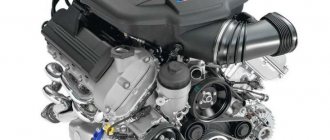
The intake system of a modern car consists of many parts and mechanisms and, depending on whether the engine is atmospheric or supercharged, it serves not only to supply air to the combustion chamber, but also for cooling if the engine is turbocharged. Also in modern production cars, vibration resonators and mufflers (similar to the exhaust system) are used to improve comfort and make the intake system operate silently. It's no secret that modern production cars are more aimed at leisurely, environmentally friendly driving. Therefore, the intake tract contains many possibilities for increasing the air supply to the engine and, ultimately, increasing power and torque.
New developments
Designers are constantly improving the design of engine components, this also applies to the intake system.
They are improving the sensors they use to improve their accuracy and durability. Basically, it comes down to using new operating principles.
More interesting are the developments concerning the design of the elements of the actuator, in particular the collector.
For example, injection engines with direct injection are equipped with manifolds with additional dampers - intake (also known as vortex). At the same time, design changes are made to the block head. This intake system implies the presence of two air supply channels to the intake valves. And the separation of these channels is done in the block head. The inlet flaps used are used to block these channels.
An intake system of this design allows for three types of mixture formation to ensure the most efficient operation of the power unit:
- Layer-by-layer
- Lean homogeneous
- Stoichiometric homogeneous
And the essence of this modification comes down to the fact that in certain modes the intake flaps block one or another channel in order to obtain the required mixture formation.
Another design option for the intake manifold is variable length. The essence of the operation of this manifold is that when idling, the air moves along a long path, but when the engine starts to operate under load, a special valve opens, which shortens the path of air movement, which ensures faster filling of the cylinders with air.
HEMI engine manifold
In the future, it is possible that some more interesting solutions will appear to obtain maximum operating efficiency of this component of the power unit.
Zero filter
In most cases, tuning the engine intake system begins with replacing the air filter with a sports filter, the so-called zero-resistance filter or simply zero filter. The principle of operation of a zero-resistance filter is quite simple; due to the use of more modern and expensive filter elements, the filter throughput increases, and the air supply resistance correspondingly decreases. Nulevik is quite easy to install, since many companies produce filters in standard housings of car intake systems, no matter if the car is carburetor or fuel-injected. But universal zero-resistance filters have become more widespread because they have an unlimited number of different shapes and mounting sizes, which in turn helps in the construction of individual engine intake systems. Also, one of the advantages of the zero filter is the ability to reuse the filter.
Design
This functioning of the intake system is ensured by the use of electronics. This means that all its constituent elements are divided into three main categories:
- Tracking devices (sensors)
- Control unit (ECU, also known as ECM)
- Actuators
The former monitor a number of parameters and, based on their readings, the ECU sends signals to the actuators, due to which the amount of air supplied is adjusted.
Audi RS4 intake system
There are quite a lot of tracking devices used in the design of the intake system. It includes sensors such as:
Audi RS4 intake system
- mass air flow or mass air flow sensor (mass flow meter);
- air temperature in the manifold;
- pressure (atmospheric, in the manifold);
- damper positions;
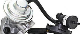
- EGR valve position.
This is a general list of monitoring devices that the intake system may include. In certain motor designs, some of them may not be present. For example, on some engines a mass air flow sensor is not installed, and its function is performed by a pressure sensor in the manifold.
The main ones of these tracking devices are the mass air flow sensor and the temperature sensor. They provide the control unit with information about the load on the power plant. The remaining sensors are auxiliary and provide information on the basis of which the ECU makes more correct decisions.
Manifold air temperature sensor
Since the intake system, like others, is controlled by the ECU, it is clear that it interacts with a number of them. Her work is “intertwined” with the systems:
- injection;
- exhaust gas recirculation;
- catching fuel vapors.
It also interacts with the brake system booster (vacuum).
Intake system elements
The design of the actuator includes a number of elements indicated above, as well as some others. It includes:
- intake;
- filter element;
- throttle assembly;
- collector;
- connecting pipelines;
- resonator.
In direct injection systems, the actuator also includes the intake flaps.
Manifold in the direct injection system of VW cars
Throttle valve (throttle)
The next step to making your engine breathe easier is to increase the throttle body diameter. Chokes, like filters, are available for standard installation and universal, for custom systems. For standard installation, they usually use chokes that are converted from serial ones by increasing the air channel and replacing the damper with the appropriate diameter. The advantages of such chokes are obvious; taking a serial product as a basis, the final cost of reworking will not be high. If the dimensions of the standard throttle do not allow you to increase the channel to the required size, then it is better to purchase a universal throttle assembly of a suitable diameter.
In addition to the pleasant moments caused by increased ease of movement, etc., vehicle owners also have a large number of problematic issues related to the technical component of the car. One of the sore topics can be called the repair and modernization of the intake and fuel systems.
New developments
Designers are constantly improving the design of engine components, this also applies to the intake system.
They are improving the sensors they use to improve their accuracy and durability. Basically, it comes down to using new operating principles.
More interesting are the developments concerning the design of the elements of the actuator, in particular the collector.
For example, injection engines with direct injection are equipped with manifolds with additional dampers - intake (also known as vortex). At the same time, design changes are made to the block head. This intake system implies the presence of two air supply channels to the intake valves. And the separation of these channels is done in the block head. The inlet flaps used are used to block these channels.
An intake system of this design allows for three types of mixture formation to ensure the most efficient operation of the power unit:
- Layer-by-layer
- Lean homogeneous
- Stoichiometric homogeneous
And the essence of this modification comes down to the fact that in certain modes the intake flaps block one or another channel in order to obtain the required mixture formation.
Another design option for the intake manifold is variable length. The essence of the operation of this manifold is that when idling, the air moves along a long path, but when the engine starts to operate under load, a special valve opens, which shortens the path of air movement, which ensures faster filling of the cylinders with air.
HEMI engine manifold
In the future, it is possible that some more interesting solutions will appear to obtain maximum operating efficiency of this component of the power unit.
Purpose of the intake system and its structure
The intake system performs a very important function, namely, it admits the amount of air required for its operation into the vehicle engine, due to which a fuel-air mixture is formed. Every modern internal combustion engine is equipped with an intake system. The system under consideration is in close interaction with other engine elements, among which are the following:
- System responsible for fuel injection.
- Elements responsible for the process of recycling gases obtained during fuel combustion.
- Equipment installed for the purpose of collecting vapors from fuel.
- Vacuum brake booster and others.
The main elements of the intake system are the air intake, air filter, throttle body and intake manifold. Depending on the specific engine design, an intake flap may also be present. All of the above elements are connected to each other by pipes.
Design
This functioning of the intake system is ensured by the use of electronics. This means that all its constituent elements are divided into three main categories:
- Tracking devices (sensors)
- Control unit (ECU, also known as ECM)
- Actuators
The former monitor a number of parameters and, based on their readings, the ECU sends signals to the actuators, due to which the amount of air supplied is adjusted.
Audi RS4 intake system
There are quite a lot of tracking devices used in the design of the intake system. It includes sensors such as:
Audi RS4 intake system
- mass air flow or mass air flow sensor (mass flow meter);
- air temperature in the manifold;
- pressure (atmospheric, in the manifold);
- damper positions;
- EGR valve position.
This is a general list of monitoring devices that the intake system may include. In certain motor designs, some of them may not be present. For example, on some engines a mass air flow sensor is not installed, and its function is performed by a pressure sensor in the manifold.
The main ones of these tracking devices are the mass air flow sensor and the temperature sensor. They provide the control unit with information about the load on the power plant. The remaining sensors are auxiliary and provide information on the basis of which the ECU makes more correct decisions.
Manifold air temperature sensor
Since the intake system, like others, is controlled by the ECU, it is clear that it interacts with a number of them. Her work is “intertwined” with the systems:
- injection;
- exhaust gas recirculation;
- catching fuel vapors.
It also interacts with the brake system booster (vacuum).
Intake system elements
The design of the actuator includes a number of elements indicated above, as well as some others. It includes:
- intake;
- filter element;
- throttle assembly;
- collector;
- connecting pipelines;
- resonator.
In direct injection systems, the actuator also includes the intake flaps.
Manifold in the direct injection system of VW cars
Features of the structure of individual elements of the intake system
As already mentioned, the mechanical part of the intake system includes such an element as a throttle valve. In a broad sense, a throttle is nothing more than a limiter.
The vast majority of engines are equipped with a throttle having a diameter of 46 mm; therefore, this element is recognized as the narrowest point in the air path of the entire vehicle. In order to modernize the engine and increase its power, it is possible to install an enlarged throttle 52. For tuning, other versions of the throttle valve are used that have an increased size, most often these are throttle 54 and throttle 56.
The indicated diameters of 52 and 54 mm are suitable for tuning a standard engine and do not require additional modifications. Throttle 56 and 58 can only be installed on a motor with an increased engine capacity. The damper operates via an electric motor and has no mechanical connection with the gas pedal installed in the car.
The next important element is the receiver. In order for the engine to operate at full power, as one of the means of modernization, many car enthusiasts replace the standard receiver with a sports intake receiver.
Any such equipment, including the VAZ sports receiver, has a rather complex operating principle. The increase in power level occurs due to the technical structure of the sports receiver, namely shortened and at the same time expanded intake channels, compared to the same standard element.
It also differs in its increased volume, which makes the air supply process more uniform. It should be noted that you can notice an improvement in the performance of the car when installing a sports receiver only when driving at medium and high engine speeds. At low speeds, the above changes actually reduce to 0.
The operation of the intake system is based on the pressure difference in the engine cylinder and the atmosphere that occurs during the intake stroke. The volume of incoming air is proportional to the volume of the cylinder. The amount of incoming air is regulated by the position of the throttle valve , depending on the engine operating mode.
On engines with direct fuel injection, intake valves operate in addition to the throttle valve. The joint operation of the throttle and intake valves provides several types of mixture formation:
- layer-by-layer mixture formation;
- poor homogeneous mixture formation;
- stoichiometric homogeneous mixture formation.
Layer-by-layer mixture formation is used when the engine operates at low and medium speeds and loads. With layer-by-layer mixture formation, the throttle valve is fully open most of the time. The damper is closed only to provide the vacuum necessary for the operation of the gasoline vapor recovery system (purging the adsorber), the exhaust gas recirculation system (bypassing exhaust gases into the intake manifold) and the vacuum brake booster (creating the necessary vacuum). The intake flaps are closed.
Stoichiometric (flammable) homogeneous (homogeneous) mixture formation is used at high engine speeds and heavy loads. The throttle valve opens according to the required torque. The intake flaps are open.
With a lean homogeneous mixture, the engine operates in intermediate modes. The throttle valve also opens according to the required torque. The intake flaps are closed.
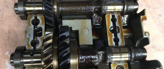
The variable valve timing system (common international name Variable Valve Timing , VVT ) is designed to regulate the operating parameters of the gas distribution mechanism depending on engine operating modes. The use of this system provides increased engine power and torque, fuel efficiency and reduced harmful emissions.
The adjustable operating parameters of the gas distribution mechanism include:
- moment of opening (closing) of valves;
- duration of valve opening;
- valve lift height.
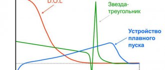
Together, these parameters make up the valve timing - the duration of the intake and exhaust strokes, expressed by the angle of rotation of the crankshaft relative to the “dead” points. The valve timing is determined by the shape of the camshaft cam acting on the valve.
Different engine operating modes require different valve timing values. Thus, at low engine speeds, the valve timing should have a minimum duration (“narrow” phases). At high speeds, on the contrary, the valve timing should be as wide as possible and at the same time ensure overlap of the intake and exhaust strokes (natural exhaust gas recirculation).
The camshaft cam has a specific shape and cannot simultaneously provide narrow and wide valve timing. In practice, cam shape is a compromise between high torque at low rpm and high power at high crankshaft speed. This contradiction is precisely resolved by the variable valve timing system.
Depending on the adjustable operating parameters of the gas distribution mechanism, the following methods of variable valve timing :
- camshaft rotation;
- the use of cams with different profiles;
- changing valve lift height.
The most common are variable valve timing systems that use a camshaft rotation:
- VANOS ( Double VANOS ) from BMW ;
- VVT-i (Dual VVT-i), Variable Valve Timing with intelligence from Toyota ;
- VVT , Variable Valve Timing from Volkswagen ;
- VTC , Variable Timing Control from Honda ;
- CVVT , Continuous Variable Valve Timing from Hyundai, Kia, Volvo, General Motors ;
- VCP , Variable Cam Phases from Renault .
The operating principle of these systems is based on the rotation of the camshaft in the direction of rotation, which achieves early opening of the valves compared to the initial position.
A variable valve timing system of this type has the following general device :
- hydraulically controlled clutch;
- control system.
Diagram of the automatic valve timing system
A hydraulically controlled clutch (commonly called a phase shifter) directly rotates the camshaft. The clutch consists of a rotor connected to the camshaft and a housing, which is the camshaft drive pulley. Between the rotor and the housing there are cavities to which engine oil is supplied through channels. Filling one or another cavity with oil ensures rotation of the rotor relative to the housing and, accordingly, rotation of the camshaft at a certain angle.
In most cases, a hydraulically controlled clutch is installed on the intake camshaft. To expand the control parameters in certain designs, couplings are installed on the intake and exhaust camshafts.
The control system provides automatic regulation of the hydraulic clutch. Structurally, it includes input sensors, an electronic control unit and actuators. The control system uses Hall sensors that evaluate the positions of the camshafts, as well as other sensors of the engine control system: crankshaft speed, coolant temperature, air flow meter. The engine control unit receives signals from sensors and generates control actions on the actuator - electro-hydraulic distributor . The distributor is an electromagnetic valve and provides oil supply to and from the hydraulically controlled clutch, depending on the operating modes of the engine.
The variable valve timing system typically operates in the following modes:
- idle speed ( minimum crankshaft speed
); - maximum power;
- maximum torque.
Another type of variable valve timing system is based on the use of cams of various shapes, which achieves a stepwise change in the opening duration and valve lift height. Well-known such systems are:
- VTEC , Variable Valve Timing and Lift Electronic Control from Honda ;
- VVTL-i , Variable Valve Timing and Lift with intelligence from Toyota ;
- MIVEC , Mitsubishi Innovative Valve timing Electronic Control from Mitsubishi ;
- Valvelift System from Audi .
These systems have basically the same design and operating principle, with the exception of the Valvelift System. For example, one of the most famous VTEC systems includes:
- a set of cams of various profiles;
- control system.
VTEC system diagram
The camshaft has two small and one large cams . The small cams are connected through corresponding rocker arms to a pair of intake valves. The large cam moves the free rocker arm.
The control system ensures switching from one operating mode to another by activating a locking mechanism. The locking mechanism is hydraulically driven. At low engine speeds (low load), the intake valves are operated by small cams, while the valve timing is characterized by a short duration. When the engine speed reaches a certain value, the control system activates the locking mechanism. The rocker arms of the small and large cams are connected using a locking pin into one unit, while the force on the intake valves is transmitted from the large cam.
Another modification of the VTEC system has three control modes, determined by the operation of one small cam (opening one intake valve, low engine speed), two small cams (opening two intake valves, medium speed), and a large cam (high speed).
Honda's modern variable valve timing system is the I-VTEC system , which combines the VTEC and VTC systems. This combination significantly expands the engine control parameters.
The most advanced type of variable valve timing system from a design point of view is based on adjusting the valve lift height. This system allows you to eliminate the throttle valve in most engine operating modes. The pioneer in this area is BMW and its Valvetronic . A similar principle is used in other systems:
- Toyota 's Valvematic ;
- Nissan VEL , Variable Valve Event and Lift System ;
- MultiAir from Fiat ;
- VTI , Variable Valve and Timing Injection from Peugeot .
Valvetronic system diagram
In the Valvetronic system, changing the valve lift height is provided by a complex kinematic scheme, in which the traditional cam-rocker-valve connection is supplemented by an eccentric shaft and an intermediate lever. The eccentric shaft receives rotation from an electric motor through a worm gear. The rotation of the eccentric shaft changes the position of the intermediate shaft, which, in turn, sets a certain movement of the rocker arm and the corresponding movement of the valve. The valve lift height changes continuously depending on the engine operating modes.
The Valvetronic system is installed only on the intake valves.
Exhaust system design
The main task of the exhaust system is to effectively remove exhaust gases from the engine cylinders, reducing their toxicity and noise levels. Knowing what the exhaust system in a car consists of, you can better understand the principles of its operation and the causes of possible problems. The design of the standard exhaust system depends on the type of fuel used, as well as the applicable environmental standards. The exhaust system may consist of the following elements:
- Exhaust manifold - performs the function of removing gases and cooling (purging) the engine cylinders. It is made from heat-resistant materials, since the temperature of the exhaust gases varies on average from 700°C to 1000°C.
- The exhaust pipe is a complex-shaped pipe with flanges for attachment to the manifold or turbocharger.
- Catalytic converter (installed in gasoline engines of environmental standard Euro-2 and higher) - eliminates the most harmful components CH, NOx, CO from exhaust gases, converting them into water vapor, carbon dioxide and nitrogen.
- Flame arrestor - installed in vehicle exhaust systems instead of a catalyst or particulate filter (as a budget replacement). It is designed to reduce the energy and temperature of the gas flow leaving the exhaust manifold. Unlike a catalyst, it does not reduce the amount of toxic components in the exhaust gases, but only reduces the load on the mufflers.
- Lambda probe - serves to monitor the level of oxygen in the exhaust gases. The system may have one or two oxygen sensors. On modern engines (in-line) with a catalyst, 2 sensors are installed.
- Particulate filter (an essential part of the diesel engine exhaust system) - removes soot from exhaust gases. It can combine the functions of a catalyst.
- Resonator (pre-muffler) and main muffler – reduce the noise level of exhaust gases.
- Pipelines – connect the individual elements of the automotive exhaust system into a single system.
The principle of operation of the exhaust system
In the classic version for gasoline engines, the exhaust system of a car works as follows:
- The engine exhaust valves open and exhaust gases with remaining unburned fuel are ejected from the cylinders.
- Gases from each cylinder enter the exhaust manifold, where they are combined into one stream.
- Through the exhaust pipe, exhaust gases from the exhaust manifold pass through the first lambda probe (oxygen sensor), which records the amount of oxygen in the exhaust. Based on this data, the electronic control unit adjusts the fuel supply and the composition of the air-fuel mixture.
- Next, the gases enter the catalyst, where they enter into a chemical reaction with oxidizing metals (platinum, palladium) and a reducing metal (rhodium). The operating temperature of the gases should not be lower than 300°C.
- At the outlet of the catalyst, the gases pass a second lambda probe, with the help of which the serviceability of the catalytic converter is assessed.
- Next, the purified exhaust gases enter the resonator and then into the muffler, where the exhaust flows are converted (narrowed, expanded, redirected, absorbed), which reduces the noise level.
- From the main muffler, exhaust gases already enter the atmosphere.
The diesel engine exhaust system has some features:
- Coming out of the cylinders, the exhaust gases enter the exhaust manifold. The temperature of diesel engine exhaust gases varies in the range of 500-700 °C.
- Then they enter the turbocharger, which performs supercharging.
- The exhaust then passes through the oxygen sensor and enters the particulate filter, which removes harmful components.
- Finally, the exhaust passes through the car muffler and is released into the atmosphere.
The evolution of the exhaust system is inextricably linked with the tightening of environmental standards for vehicle operation. For example, starting from the Euro-3 category, the installation of a catalyst and particulate filter for gasoline and diesel engines is mandatory, and replacing them with a flame arrester is considered a violation of the law.