Electrical equipment of the car
- a set of devices that generate, transmit and consume electricity in a vehicle.
The electrical equipment of a car is a complex set of interconnected electrical and electronic systems, instruments and devices that ensure reliable operation of the engine, transmission and chassis, traffic safety, automation of vehicle work processes and comfortable conditions for the driver and passengers.
What are car wiring diagrams?
What devices and elements does the vehicle's electrical wiring and electrical equipment system include? A schematic electrical diagram is a visual representation where all the icons of the components used are indicated without exception. All devices are located in a specific order on the diagram, and they can be connected to each other in either a serial or parallel manner. It must be taken into account that the electrical diagram of a car or truck itself does not actually show the actual location of the equipment. It only shows how all consumers and energy sources are connected.
Regardless of the machine, the circuit includes the following components:
- power system equipment used to generate voltage;
- devices used to convert energy;
- In addition, the network also includes components used to transmit current, that is, conductors.
What opportunities open up for a car owner who understands the circuits?
Every car owner should understand the auto electrical circuit, since if problems arise in the operation of the equipment, you can deal with the breakdown yourself. Naturally, if more complex problems occur in the operation of the network and equipment, then it is unlikely that you will be able to identify them yourself without experience. Especially when you consider that modern cars use more complex circuits, which is associated with the use of a larger number of various devices.
Also, the need to understand the operation of a particular circuit for a car may arise for those car owners who want to make adjustments to the operation of the system. For example, if you are planning to improve and tune your vehicle, this does not necessarily mean using upgraded body kits or bumpers. If the interior is being tuned, the car owner can install a new audio system or air conditioner, in which case it is impossible to do without making changes. In addition, you need to understand the operation of the circuit even if you decide to install an anti-theft installation yourself.
Those motorists who periodically use a trailer should also be able to understand the circuit, since our compatriots often face connection problems. One way or another, if you want to install additional devices and add their system, then understanding the electrical circuit is simply necessary.
Battery types
Before we find out how many amperes are usually in a classic 12-volt car battery, let's look at the types of power sources. There are the most popular battery options, such as acid and alkaline. In the first case, metal plates (electrodes) are immersed in a solution of sulfuric acid, and in the second case, the liquid is an alkaline solution.
For northern regions, it is not recommended to use alkaline power sources, as they do not perform well at low temperatures.
Regardless of how many amperes there really are in an alkaline car battery, they are available in two versions: nickel and lithium. The former may contain cadmium or metal hydroxide in combination. Due to their large dimensions, such devices are more in demand on electric forklifts or trucks, since there is more space for the placement of cells with a lower specific current compared to acid analogues.
Lithium power supplies are cheaper to manufacture, but in practice they are very sensitive to low temperatures. This equipment has proven to be in demand in electric vehicles.
Acid batteries are available in the following types:
- Antimony. Lead plates include more than 5% antimony. Although such a battery is capable of withstanding a significant number of discharges/charges, due to other disadvantages it is not used in modern cars.
- Low antimony. They are manufactured using a similar technology as antimony batteries, but with a lower percentage of antimony. They have better practical characteristics.
- Calcium. The plates in them are made with the addition of calcium compounds (without antimony). In some models, the electrodes include silver alloys. Power supplies are quite sensitive to frequent deep discharges, but have stable operating parameters.
- Gel or AGM batteries. This technology assumes that the electrolyte is in a jelly-like (gel) state. Such models are significantly higher in price than liquid analogues - 2–3 times. Their advantages are high resistance to frequent deep discharges and good output parameters, but their disadvantages are the need for a high-quality charger with reduced current parameters and stable consumers.
How does the electrical equipment of any car work?
As stated above, any on-board network includes energy sources, consumers, conductors, and control components. Energy sources include a car battery and a generator unit. The purpose of the battery is to supply current to all consumers when the engine is turned off, when it is started, and also when the power unit is operating at low speeds. But the main source of energy is still considered to be the generator unit, which makes it possible to provide power to all equipment and restore the battery charge. It must be taken into account that the battery capacity, as well as the power of the generator device, must fully comply with the technical parameters of the voltage consumers; this is necessary to maintain the energy balance.
As for consumers, they are all divided into several groups:
- Basic. These energy consumers include the fuel system, ignition, injection, ECM (engine control), automatic transmission, as well as power steering, in particular, ESD.
- Additional. These include a cooling system, lighting and optics, active and passive safety, air conditioning, stove, car alarm, acoustics, and a navigation system.
- There are also short-term consumers. Such consumers include comfort systems, starting systems, horn, cigarette lighter (the author of the video is the Kroom&coTV channel).
Also, any wiring system involves the use of control components. With their help, coordinated operation of energy sources, as well as its consumers, is ensured. The list of control components includes mounting blocks with safety devices and relays, control modules. These devices are usually located in a decentralized manner. In modern vehicles, most of the options that the relay must perform are assigned to control modules, that is, control units. Also, many cars today use multi-complex systems, in particular, data buses that connect electronic units.
Car device
All elements of a car’s electrical equipment can be divided into two groups: sources of electrical voltage (or power supply system), and consumers of electrical energy.
The power supply system is designed to power all electrical consumers that perform functions necessary for the normal operation of the vehicle. The basis of automotive power supply systems are portable sources of electricity - batteries and generators.
A modern car is equipped with various devices that use electrical energy to operate. Such devices are called electrical consumers, which, together with energy sources or energy storage devices, form the vehicle’s electrical equipment system.
The use of electrical and electronic devices for the operation of various systems, instruments, elements and mechanisms of a car is very convenient from a technical point of view, since electricity can be accumulated, it is easily transmitted over a distance, it is easy to obtain by converting other types of energy, and, importantly, without any or use the treatment for its intended purpose.
The only problem that remains problematic is the issue of storing electricity for future use, since modern storage devices - accumulators (rechargeable batteries) - have limited capacity and are not capable of ensuring the functioning of consumers for a long time.
For this reason, cars are equipped with electric machines - generators capable of converting mechanical energy into electrical energy, taking part of the mechanical energy from the running engine.
The electricity thus obtained is used to operate consumers when the engine is running, as well as to replenish and maintain the necessary reserve in the battery.
The main consumers of electricity in a car are the ignition system, microprocessor injection and ignition control system, engine starting system, lighting and alarm systems, instrumentation and various additional equipment and devices. The amount of electrical equipment on cars increases every year, so developers and designers have to constantly work to improve the power supply system.
As a rule, electric current of 12 or 24 V is used to power electrical equipment of automobiles.
Cars use parallel connection of devices, and since the main elements of the car are made of metal, which is a good conductor of current, as a rule, electrical equipment systems are constructed using a single-wire circuit.
The second wire in this case is the metal parts of the car, i.e. its body or the so-called “ground”.
To describe the operation of electrical equipment, an electrical circuit diagram is used (Fig. 1.1, a), which gives a complete picture of the interaction of all its elements and facilitates troubleshooting. The main supply circuits in the electrical circuit diagram are located horizontally, and electricity consumers are located between them and the “ground” of the vehicle.
The connection diagram (Fig. 1) shows the actual location of the electrical equipment elements on the car and their actual connection to the vehicle’s on-board network, indicating the exit from the bundle of each wire, the location of the adapter blocks, circuit protection elements, etc.
As a rule, the negative terminals of the electrical network are connected to the ground of the car.
The sources of electricity in a car are the generator and the battery, which are connected in parallel to each other.
When the engine is running, the generator is the main source of electricity and provides power to consumers and recharges the battery. When the engine is not running, the function of the source of electricity passes to the battery, which must also ensure reliable starting of the engine.
- Since automobile generators operate in modes of variable speeds and loads that vary over a wide range, various voltage regulators are used to automatically maintain the electrical voltage at a given level.
- ***
- Working principle of a lead-acid battery
Home page
Distance education
- Group TO-81
- Group M-81
- Group TO-71
Specialties
Academic disciplines
Olympics and tests
Purpose and general characteristics of electrical equipment
The electrical equipment of KamAZ and Ural vehicles is a complex set of devices combined into an independent electrical system, which in turn consists of power supply, starting, light signaling, external and internal lighting, sound alarm, heating and ventilation systems.
Basic aspects of correctly reading an equipment electrical diagram
So, how to read car diagrams and what you need to know about deciphering them? As you already understand, without knowledge of decoding you will not be able to repair wiring and equipment if necessary. A detailed diagram for a specific car model should be noted in the service manual for the car. Looking at it, you can see dozens of various symbols of electrical equipment that are connected by lines. Each of these lines is painted a certain color - this is the color of the wires in the wiring system (video filmed by the MR.BORODA channel).
More modern cars use complex circuitry because these vehicles are equipped with more equipment and devices. In such electrical circuits, conductors may be indicated as segments or with breaks.
What aspects should be taken into account to decipher the electrical circuit of the machine:
- As we have already reported, all electrical circuits are marked with a color corresponding to their actual state. This greatly simplifies the process of repairing and replacing wiring. The color of the conductors itself can be single or double, this indicates whether it is the main cable or an additional one. If additional conductors are meant, then on the electrical circuit itself they are usually marked with hatched segments, which are either longitudinal or transverse.
- If in your car several electrical circuits are located on one harness, and they are marked similarly, then such circuits are characterized by galvanic resistance. That is, these cables are simply connected to each other.
- If the chain fits into the harness, it will be marked with a slight deviation in the specific direction it is facing.
- Typically, on any electrical circuit there are several wires of the same color, usually black. In this case we are talking about electrical circuits connected to ground, that is, the car body. Such contacts are called mass.
- If we talk directly about the relay, then in this case the contacts are indicated in a state when no energy is transmitted through the winding of the device. If the operating state of the device is standard, then these elements may differ from each other, since they can be open and closed.
- In addition, by looking at the electrical diagram, you will see that additional symbols may be marked on the circuits themselves. Namely, we are talking about connecting an electrical circuit to an energy consumer. Such a designation will enable the consumer to find out exactly where the circuit is connected, without exactly tracing its routing.
- If you notice that specific numbers are indicated on devices or equipment, then these numbers must correspond in any case. For example, if there is a circle around the number, this indicates that this is the point where the circuit connects to the negative terminal. If you are interested in combinations of letters and numbers, then this is how plug connections are marked.
Photo gallery “Electrical circuit designations”
What is the normal leakage current of a car battery?
Current leakage is an unregulated loss of electricity that causes the battery to discharge. The cause of this defect may be damage to the wiring, battery failure, malfunction of volatile connected devices (for example, a tape recorder), and so on.
It should be understood that there is also the so-called natural self-discharge of the battery, the occurrence of which is not related to the presence of a malfunction in the car.
The level of natural discharge is determined as follows:
- Battery self-discharge. Even the best quality battery discharges over time due to natural reasons. The self-discharge level of the battery is usually 1-4% depending on the quality of the battery, the ambient temperature and the nominal capacity of the battery.
- Connected devices. Electrical devices connected to a car battery consume energy even when at rest. The alarm system consumes the most (about 25 mA per day), but some other devices also drain the battery quite well - an immobilizer (15-20 mA), a tape recorder (3-5 mA), a central controller (5-10 mA).
Normally, the natural discharge of the battery is 20-40 mA per day. In this scenario, the car can sit in the parking lot for several weeks - and after that it can be started without problems. If the car has an immobilizer or an “advanced” alarm system, then in this case the rate of natural leakage increases to 50-70 mA per day .
In this case, the battery charge will last for 5-7 days, which is a very good indicator. If the current leakage is 80 mA or more, then this indicates the presence of a hidden defect, and the driver will have to charge the battery literally before every trip.
Video “How to independently identify electrical problems?”
If you don’t know how to identify problems with your car’s electrical wiring system with your own hands, we recommend that you watch a video that describes this process in detail (the video was published by the Autoelectrics HF channel).
More and more modern cars are becoming a veritable collection of electronic devices. Indeed, with an increase in comfort and comfort, a large number of different instruments and control devices are used in cars. All this complicates the maintenance of the electrical part of the car and requires the ability to read electrical diagrams. In this article we will tell you what electrical diagrams are, why you need to be able to read them, and tell you about the basic symbols.
What is an electrical circuit?
An electrical circuit is a graphic (on paper) representation of special symbols and pictograms that have a parallel or serial connection. The diagram never shows an actual image of a collection of objects, but only shows their connection with each other. Thus, if you know how to read diagrams correctly, you can understand the principle of operation of a particular device or system of devices.
Almost all electrical circuits contain the following items:
- Power supply
. This is either a generator. - Conductors are wires
through which electrical energy is transmitted through a circuit. - Control equipment
is devices designed to close or open an electrical circuit, which may or may not be present in the circuit. - Consumers of electrical energy
are all devices or devices that convert electrical current into another type of energy. For example, a cigarette lighter converts electrical current into thermal energy.
Devices that consume a lot of energy
So what electrical appliances consume how much energy? Here's a short list:
- starter – from 800 to 3000 W;
- car air conditioning – from 80 – 600 W;
- seat heating function – 240W;
- electric windows – approximately 150W.
The rest of the devices, such as fog lights, low beam headlights, glow plugs, injection system, car signal, as well as the fuel system pump, consume electricity in the range of approximately 70 to 190 W. It is obvious that the starter is the most “gluttonous” electrical device. Maximum energy is required to start a car engine, because the power of the starting current is many times greater than its rated level. The second place in terms of energy consumption is rightfully occupied by a car air conditioner, the main role in which is played by its compressor, which absorbs the lion's share of engine power.
Next comes the seat heating function, which, from the moment it is activated, contributes to a gradual increase in temperature and heating of the seats, and, consequently, energy consumption and load on the generator. Please note that the properties and performance of a discharged car battery will differ greatly from the parameters set by the manufacturer. Therefore, every car enthusiast is advised not to oversaturate the energy balance when using a car, for example, by turning off various gadgets, chargers, navigator, side lights when leaving the car for a long time.
Why do you need to be able to read electrical diagrams?
The owners of the first cars did not need such knowledge. The fact is that their electrical equipment was limited, which made it easy to remember the connection of the circuit elements and learn all the wires by heart. Another thing is modern cars, where a large number of electrical devices and instruments are mounted. This is where an electrical diagram is required.
You may need the ability to read a diagram when operating any car. This will help you easily find and eliminate minor faults associated with the failure of an electrical appliance. After all, diagnosing faults and then subsequent repairs can cost quite a considerable amount. Why not do it yourself?
In another case, knowledge of the circuit will help you when connecting new electrical appliances. For many drivers, the diagram helps install alarm systems, auto start and many other devices where connection to the vehicle’s on-board network is mandatory.
Many drivers find it difficult to connect the trailer circuit to the vehicle's electrical network. Knowing the elements of the circuit will help you quickly find the fault and promptly fix it.
Symbols on car electrical circuits
The symbols of electrical circuits are not anything complicated. To understand them, you need to have a minimal understanding of the action of electric current.
As is known, current is the ordered movement of charged particles along conductors of electric current. The role of conductors is played by multi-colored wires, which are indicated in the diagram as straight lines. The color of the lines must necessarily match the color of the wires in reality. This is what helps the driver understand thick wiring harnesses and not get confused.
Various contact connections are indicated using special numbers, which are found both on the diagram and at the connection points. As a rule, relays that have many contact pins are required to have such numbers. The elements of the electrical circuit in the diagram are signed using numbers. At the bottom of the diagram or in the form of a separate table, a special decoding of these numbers is displayed, which displays the name of the circuit element.
Let's summarize. Reading electrical diagrams is a fairly easy task. The main thing is to correctly interact with the symbols and be able to understand the symptoms of a malfunction in order to promptly and correctly determine the type and location of the malfunction on the diagram.
Every car owner should know how to correctly decipher the symbols present in the electrical circuits of a car. Indeed, in practice, a malfunction in the operation of electrical equipment can overtake the driver at any time, even on the road. Therefore, it is important to understand this issue so that, if necessary, you can fix the problem yourself.
Vehicle electrical equipment and additional equipment
A modern car has a complex electronic “stuffing”, which is called in one general word “electrical equipment”. The electrical equipment of a vehicle is its lighting, engine starting mechanism, vehicle security, heater and air conditioner, etc. Electricity is generated from sources (battery and generator) and transmitted to consumers.
Current consumers in the electrical system of a passenger car are: the engine starting system, the vehicle ignition system, the lighting and alarm system, instrumentation and additional equipment, which may differ for each vehicle.
We have already become acquainted with the engine ignition system earlier (see Chapter 2, section “Ignition System”).
Let us only recall that for the operation of an internal combustion engine, a spark plug is required, which produces an electric spark that ignites the working mixture in the cylinder (in diesel engines, glow plugs are used). And this spark appears due to the presence of an electrical equipment system in the car. We will get acquainted with other consumers of electricity in this chapter. In other words, further we will learn about how the electrical energy of a modern car is generated and used. Sources of electric current
Electric current in a car is generated from two sources: the battery (battery) and the generator.
The task of the battery (Fig. 4.1) is to provide electricity to the corresponding vehicle equipment when the engine is turned off, as well as when the engine is running at low speeds. The battery is usually located in the engine compartment on a special metal shelf, but in some car models it can also be installed in the passenger compartment.
The battery has a plus and a minus at the corresponding poles. The negative pole is connected to the car body and provides, as drivers say, “access to ground.” The positive terminal is connected to the car's electrical circuit, through which electricity is transmitted.
The battery includes six separate batteries located in one housing and connected in series to form a single electrical network. Electrochemical processes take place in each battery, resulting in a current of 2 volts. It is easy to calculate that a total of 12 volts of direct current is generated at the battery poles (six batteries of two volts each).
The battery is marked as standard. For example, the marking 6ST-60A is deciphered as follows:
? 6 - the number of batteries in the battery (for all passenger cars this figure is unchanged);
? ST is a type of battery, in this case a starter battery, which allows you to start the engine using a powerful consumer of electricity (starter);
? 60 is the capacity of the battery, which is measured in ampere-hours (in the example under consideration - 60 ampere-hours);
? A - designation of the material from which the battery case is made (in the example under consideration - polypropylene).
The more power required to start the engine, the greater the capacity of the battery. For standard Soviet Zhiguli cars, batteries with a capacity of 55 amp-hours were used. But such a battery may not be enough to start diesel engines - they need at least 60–65 ampere-hours.
Typically a new battery lasts for 6-7 years. After this, it must be replaced, although sometimes you can extend its life by periodically recharging using a special charger.
The generator (Fig. 4.2) is a source of electric current that provides electricity to all consumers when the engine is running at high and medium speeds. In addition, the most important function of the generator is to recharge the battery (also while the engine is running). Without a generator, the new battery will discharge very quickly and will become impossible to use.
The generator is connected to the car's electrical circuit in parallel with the battery. Consequently, it will supply consumers with electric current and charge the battery only when the voltage it produces is greater than the voltage produced by the battery. This happens when the car engine operates at speeds above idle: after all, the voltage of the electric current produced by the generator directly depends on the rotation speed of the generator rotor, which is driven by the engine.
It should be noted that sometimes the voltage generated by the generator may be greater than necessary. To prevent this situation, the car uses a special device called a voltage regulator. This device operates in tandem with a generator, limiting the voltage of the current it produces and regulating it in the region of 13.6-14.2 volts. The voltage regulator can be built into the generator, or it can be located in the engine compartment separately from the generator.
There is a specially designed bracket for mounting the generator on the engine. The generator is driven from the engine crankshaft via a belt drive. On many machines, with the help of one belt, a drive is created from the crankshaft to the generator, a constantly running fan and to the water pump (pump), i.e. all these units work as if in one connection, although they perform completely different functions. However, this is not necessary - often the generator has a separate drive belt. In any case, you need to periodically check the belt tension and, if necessary, adjust it by tilting the generator housing. Remember that an insufficiently tensioned belt, firstly, makes unpleasant whistling and creaking sounds during operation, and secondly, it quickly fails.
On the instrument panel of any car there is always a red battery charge light.
It always lights up when the ignition is turned on and goes out after the engine starts. If the light does not go out while the engine is running, this indicates problems in the power supply system (the generator has probably failed). Lighting and signaling devices
Lighting devices are designed to indicate the dimensions of a vehicle when driving at night and in conditions of poor visibility, as well as to illuminate the road and interior of the vehicle (engine compartment, interior, trunk). The lighting devices are headlights (block headlights), license plate lamps, interior lighting lamps, trunk lighting lamps, engine compartment lighting lamps (under the hood) and rear lights.
The block headlight (Fig. 4.3) consists of a housing, a diffuser and a reflector. Inside the housing there is a lamp inserted into a socket, which can operate in two modes: low beam headlights and high beam headlights. The low or high beam is switched on using a switch located in the cabin. There is also a side light bulb inside the headlamp, which is designed to indicate the dimensions of the car if necessary (there is also a toggle switch to turn on the dimensions).
Modern headlights often also contain a turn signal bulb, but it can also be located separately - it all depends on the specific car model.
Tail lights (Fig. 4.4) in modern cars are also, as a rule, made in one housing.
Tail light includes:
? brake lamps (turn on automatically when the driver presses the brake pedal, and turn off when the pedal is released);
? reverse lamps (light up automatically when the driver engages reverse gear, and go out when it is turned off);
? direction indicators;
? parking lights.
The driver turns the turn signals on and off using a special switch, which is usually located on the steering column. All direction indicators work simultaneously when the driver turns on the hazard warning lights (there is a special button for this). The procedure for using hazard warning lights is regulated by current traffic regulations.
A sound signal is an alarm device designed to soundly alert other road users of an impending danger.
It is activated by pressing a special button or key, usually located on the steering wheel. The procedure for using a sound signal is prescribed in the traffic rules. Engine starting system
To turn on the engine, an engine starting system is designed, consisting of an ignition switch, a starter with a traction relay, a starter drive mechanism and a starter activation relay.
The engine is started using a starter (Fig. 4.5).
This device is a DC electric motor. When the driver turns the ignition key to the “Start” position, electric current is supplied through the relay from the battery to the starter windings. As a result, the traction relay is activated, a special starter gear engages with the engine flywheel and turns it. Since the ignition is already on, the engine starts and starts running.
Note that the starter is used solely to start the engine; the rest of the time this device “rests”. The starter operating process can be divided into three key stages.
First, a special gear located on the starter armature shaft engages with the engine flywheel ring gear (this is possible thanks to the drive mechanism). Visually, this can be represented as follows: take two gears, one of which will illustrate the flywheel ring gear, and the other the starter gear, and engage them. If you turn the “starter gear”, then the “flywheel ring gear” will certainly turn as well.
Next, the starter shaft, together with the gear engaged with the flywheel, begins to rotate, as a result of which the flywheel rotates, and therefore the engine crankshaft rotates, after which it starts.
Then, when the driver starts the engine and releases the ignition key, turning off the starter (the key can only be held in the “Start” position by force, since it automatically returns), the starter gear disengages to the side (the gear teeth will remain at the same level, but only to the side). It is in this position all the time when the engine is running or turned off, and engages with the flywheel only when the driver turns the ignition key to the “Start” position.
Remember this.
Immediately after starting the engine, you must turn off the starter by releasing the ignition key. Forcibly holding the key in the “Start” position while the engine is running can quickly damage the starter: the heavy rotating ring of the flywheel will, at a minimum, simply “grind” the starter gear. It is possible that the starter will receive other damage (the traction relay will burn out, etc.). For the same reason, you should never turn on the starter while the engine is running.
When used correctly, the starter is a fairly reliable device that can serve throughout the entire life of the vehicle.
Instrumentation
To promptly inform the driver about the condition of important components and assemblies of the car, the current speed limit, the availability of fuel, the amount of distance traveled and other important factors in the car, control and measuring instruments (abbreviated as instrumentation) are used. The instrumentation is located in a place convenient for the driver’s view, namely, on the instrument panel (instrument panel), located immediately behind the steering wheel (Fig. 4.6).
A typical instrument panel contains indicator lamps, an odometer (odometer, separately for total and daily mileage), a coolant temperature sensor, a speedometer, a fuel level sensor and an engine speed indicator (tachometer). Also, the instrument panel may include other instrumentation - this depends on the car model.
Everyone should know this.
A general rule applies for all instrumentation: when the engine is running, under no circumstances should any red light (indicator) be illuminated or the arrow of any indicator be in the red sector. Such instrument readings inform the driver that there are serious problems in the corresponding unit, and the vehicle cannot be operated until they are eliminated.
Indicator lamps provide the driver with information about the current state of systems, components and assemblies. In particular, when the ignition is turned on, the red battery charging and oil pressure lamps light up - they should go out after the engine starts. If the car is parked in the handbrake, then on the instrument panel when the ignition is on, the corresponding red light will light up, which will go out only after the parking brake system is turned off.
When you turn on the low or high beam headlights, the lamps on the instrument panel light up, green and blue, respectively. When the driver turns on the turn signal or hazard lights, the corresponding indicator on the instrument panel begins to flash, which is accompanied by characteristic audible clicks.
The tachometer (Fig. 4.7) shows how many revolutions per minute the engine crankshaft makes in the current operating mode. It is usually measured in thousands, so the dial contains the numbers 1, 2, 3, etc., and when the hand points to a number, you should multiply it by 1000.
The fuel level sensor (Fig. 4.8) informs the driver about the amount of fuel currently available in the fuel tank. When there is too little fuel left, the needle approaches the red sector, and in many cars the corresponding lamp also lights up (sometimes it looks like a gas station). You should not ignore the alarming readings of the sensor - otherwise you risk stalling on the road due to lack of fuel in the fuel tank.
The odometer shows the number of kilometers traveled by the car, and in modern cars separate counters are designed for total and daily (or for any arbitrary time interval) mileage.
A speedometer (Fig. 4.9) is a device that informs the driver about the current speed limit (simply put, at what speed the car is currently moving). The readings of this device are extremely important for choosing the correct speed and for preventing violation of the speed limit established on a given section of the road by the current Traffic Rules.
The coolant temperature sensor (see Fig. 4.8) informs the driver whether the engine cooling system is functioning normally.
We said earlier that the operating temperature of the coolant should be between 80–90 degrees Celsius. If the sensor needle moves to the red sector, it means that the liquid temperature is approaching 100 degrees or has already reached it. In such a situation, you should immediately turn off the engine and allow it to cool. Additional equipment of a modern car
Additional equipment of a car is intended mainly to improve the comfort and convenience of travel, as well as to ensure the necessary driving conditions. Among the most common types of additional equipment are: interior heater, air conditioning, radio, windshield wiper and washer, heated windows, mirrors and seats, electric window and seat lifts, electric headlight range control, headlight cleaner and washer, refrigerator, satellite alarm system, etc. .
The interior heater is simply called a “stove”; without it, in most Russian regions you can operate a car for no more than three to four months (otherwise you can simply freeze). The heater is also used to blow glass, eliminating condensation that appears on them (the so-called “fogging”). When a car engine overheats, sometimes turning on the heater at full power helps.
The windshield wiper and washer systems provide visibility when driving in rain or snow, or when driving on muddy roads.
Please note.
Traffic regulations prohibit the operation of a vehicle if its designed windshield wipers and washers do not work.
Not all cars are equipped with a heated glass and mirror system (this does not apply to the rear window - all modern cars have it heated). These devices help quickly remove ice and snow from car windows and mirrors. Not all cars also have a heated seat system, but if it is, then getting into a cold car in winter will be much more pleasant.
Another popular device is an air conditioner. In hot weather, this device can turn a tiring car ride under the scorching sun into a real pleasure. Having an air conditioner is especially important for people who are prone to motion sickness when driving in a car (for example, the elderly or children). On the other hand, you should use the air conditioner with caution, since there is a high risk of catching a cold.
Many modern foreign cars have electric headlight range control (Fig. 4.11). This device allows the driver to adjust the direction of the headlights from his seat - higher or lower.
Headlight cleaners and washers are not devices that every modern car must have (unlike a windshield cleaner and washer). But when driving on dirty roads, these devices are very convenient because they allow you to clean the headlights from dirt while driving.
What are electrical circuits?
In order to correctly read the fundamental decoding of automobile electrical circuits and know what the symbols mean in electrical circuits, let’s first understand the concept. A schematic diagram of a car's electrical equipment is a graphical representation that shows pictograms of various components. These components of the system device are installed in a certain order on the electrical circuit and they can be connected to each other either in parallel or in series.
It should be noted that the car electrical diagram does not reflect the actual location of these components, but rather demonstrates their relationship with each other. That is, a car enthusiast who can figure out the structure of the system with his own hands and read the transcript will understand the principle of operation of electrical equipment at one glance.
Any car electrical diagram demonstrates several groups of components:
- power system devices designed to generate voltage;
- elements intended for energy conversion;
- as well as system devices necessary to transmit voltage (conductors perform this function).
The system's power supply devices are various galvanic components characterized by low internal resistance. All kinds of electric motors are designed to convert energy. In any case, the electrical circuit diagram of a car contains objects conventionally marked on it.
VRemont.su - repair of photo video equipment, household appliances, review and analysis of the service sector market
For auto electronics, the following types of circuits are installed: circuit diagram and wiring diagram. The schematic diagram is intended to facilitate the detection of faults and understanding of the operation of the vehicle electrical equipment system and its control.
Schematic diagrams of electrical equipment of cars should provide a complete picture of the interaction of all products included in the circuit, and the ability to trace current paths in electrical circuits.
The wiring diagram shows the actual connection of the products included in the circuit and is intended to facilitate the installation and repair of the vehicle's electrical equipment during its operation. The location of products on the diagram should be determined by their actual location on the vehicle. The diagram should show real bundles of wires indicating the exit points of each wire from the bundle.
In the general diagram of the electrical equipment of a car, in addition to individual devices, it is possible to distinguish groups of devices that form independent systems and have their own connection diagrams.
The schematic diagram indicates the areas where the functional systems are located.
Vehicle electrical equipment that consumes high current and operates for a short time, as well as devices whose operation is necessary in emergency situations, are connected to the ammeter-battery line. This group of consumers includes a starter, cigarette lighter, horn, engine compartment lamp, and portable lamp socket.
The remaining consumers are connected to the ammeter-generator line. In this group, depending on the nature of the work, the devices are connected: through the ignition switch, if they operate only when the engine is running; to the ammeter-generator line, if the devices consume low current and operate for a long time both when the engine is running and when parked; through the central light switch - all lighting equipment.
All circuits are protected by fuses. Battery charging circuit protection is optional.
The ignition and starting circuits are not protected from short circuits, so as not to reduce their reliability in operation.
On cars, a single-wire system for switching on electrical equipment is used, in which the second wire is the ground of the car. The single-wire system reduces the number of wires and greatly simplifies the entire wiring system. However, if the insulation is broken, the wires can touch metal parts of the car, which causes a short circuit, and if the fuses are faulty, the possibility of a fire. Low voltage PGVA wires are used in automobile electrical circuits.
For ease of installation and protection of wires from damage, they are connected into braided bundles. The ends of the wires in bundles have tips for screw terminals or plugs. Automotive wires have different colors to make them easier to find in a bundle. For the same purpose, the output terminals on the products and the wire lugs are marked.
A feature of the electrical circuits of diesel vehicles is that the rated mains voltage is increased to 24 V, which is due to the need to ensure reliable starting of the diesel engine. To reliably start a diesel engine, the starter power must be 7-8 kW, and the starting current can reach 500-800 A. At a mains voltage of 12 V, the current will double and an unacceptable increase in battery capacity will occur. However, with a 24 V network voltage, it is impossible to unify electrical equipment, the service life of automobile lamps is reduced, and the corrosion of electrical connections (especially plug-in ones) increases.
When replacing electrical equipment in a car circuit (lamps, control devices, electric motors, etc.), it is necessary to pay attention to the rated voltage of the device, since a device designed for a voltage of 12 V and connected to a circuit with a voltage of 24 V will instantly fail . 24 V car lamps with the same power have a thinner filament, so they do not tolerate vibration well. To increase the service life of lamps when using a 24 V voltage, lighting devices (headlights, taillights) are often mounted using shock absorbers that reduce vibration at the lamp installation site.
In order to unify electrical equipment, some cars with diesel engines use a 12/24 V voltage system. In this case, all consumers have a rated voltage of 12 V, a generator of 14 V, and a starter of 24 V. When starting the engine, two 12 V batteries are switched on for power starter sequentially with a special switch. When the engine begins to work independently, the batteries are connected to the electrical circuit in parallel. However, with this design, the reliability of the battery switch is reduced. In addition, there is a difference in the charging mode of the batteries, since the length of the wires (charge circuit resistance) to each battery is different due to the presence of a battery switch.
The advantage of the circuit is reliable starting (24 V instead of 12 V), long lamp life and the possibility of unifying devices for 12 V voltage.
Why understand electrical circuits?
Every vehicle owner should be able to read a schematic diagram of the device designation, since in the event of a breakdown this will save money on repairs. Of course, without the participation of specialists, repairing more complex system faults will be problematic. Moreover, the electrical equipment of a car, especially a modern one, is a rather complex system that will not tolerate errors. But if the breakdown of the electrical circuit is not particularly significant or you just need to connect the optics, then doing it yourself is quite possible.
In addition, understanding what elements a car’s electrical equipment consists of is very important for those car enthusiasts who want to make changes to the operation of the system. For example, today many domestic drivers do their own vehicle tuning in various ways. This doesn’t have to be the installation of new bumpers or body kits - sometimes you want to do the interior tuning yourself by installing a new multimedia system or air conditioning. In addition, it is necessary to understand the electrical circuit of the car with your own hands even if you are installing an anti-theft system - after all, it is impossible to do without protecting the car at such a time (the author of the video is Avtoelectrica HF).
It is also necessary to read the electrical diagram for those drivers who have a trailer, since it is often difficult to connect it to the system with your own hands. In any case, if you decide to install additional equipment into the system, then the ability to read an electrical diagram will be useful to you. At a minimum, without this you will not be able to properly connect the wires with your own hands and configure the equipment.
How to read car electrical diagrams - basic symbols
So, let's consider the main points that will allow you to correctly read the electrical circuit of the equipment of any vehicle. After all, as stated above, without this knowledge it is simply impossible to repair devices yourself. Of course, no device can function without voltage supplied to the device through internal conductors.
The electrical diagram of the vehicle with the designation of all elements must be in the service book for the vehicle. Looking at it, you will see many different symbols of instruments and devices connected to each other by lines. It should be noted that each of these lines can have its own specific color, which in fact should correspond to the actual color of the wires of the electrical circuit (the author of the video is Avtoelectrica HF).
If the car is equipped with multiple electrical appliances and devices, then a large number of components will be marked on the diagram. Accordingly, the wiring itself may appear with breaks and segments. This may be confusing at first, but there is nothing difficult about it; it is quite possible to figure it out on your own.
Any scheme consists of the following elements:
- Power supply device. In this case, this function is performed by the vehicle’s battery or generator.
- Conductors, that is. These components allow current to be transmitted across the network.
- Control equipment. Such devices are necessary for closing the electrical wiring or opening it if necessary. It should be noted that devices of this type may or may not be present on the electrical circuit.
- Direct voltage consumers. This item includes all electrical equipment that consumes energy by converting current into another type of energy. For example, if we are talking about a cigarette lighter, then this element converts voltage into thermal energy.
If there is a need to repair a vehicle with your own hands, it is necessary to take into account the basic principles when deciphering the diagram:
- Any conductors, as mentioned above, are marked with a certain color on the diagram. As for the color itself, the wire can have one color or two, that is, it can be either primary or additional. If we are talking about additional components, then strokes must be applied to them - they can be transverse or longitudinal.
- If several wires are installed on one harness and are marked the same, then they have a galvanic connection. In other words, these conductors are simply connected to each other.
- In any diagram, if a conductor enters a bundle, it should slope slightly towards where it is located.
- In practice, that is, on most diagrams, conductors are marked in black, which are connected directly to the mass of the vehicle, that is, to its body.
- As for relays, their contacts are marked in the state when no voltage passes through the device winding. In the standard state, these components are different because they can be either closed or open.
- You may also notice that conductors may have certain markings on them, particularly where the conductor connects to the equipment. Thanks to this designation, the driver can immediately understand where this conductor goes without having to trace the circuit as a whole.
If certain numbers are indicated on certain mechanisms, then they must correspond to the numbers. If this or that number is marked in a circle, then this indicates that you have a conductor connection with a minus. As for the number and letter combinations, they correspond to detachable connections.
The service book may include a table that will allow you to easily decipher certain network elements specific to a particular vehicle model. In general, if you have a need to decipher a diagram, then the most important thing is to be diligent in order to understand what this or that designation means. Having understood the principle of decoding itself, you can easily determine the purpose of all elements.
Foreign cars have different markings, but the principle is the same.
What are electrical circuits?
An electrical circuit is an ordinary graphic image that shows pictograms of different elements arranged in a certain order in a circuit and connected to each other in series or parallel. Moreover, such drawings do not display the actual location of these elements, but only indicate their relationship with each other. Thus, a person who understands them can determine at a glance the operating principle of an electrical appliance.
Diagrams always depict three groups of elements: power sources that produce current, devices responsible for energy conversion, and nodes that transmit current, their roles being played by different conductors
. Galvanic cells with very low internal resistance can act as a power source. And electric motors are often responsible for energy conversion. All objects that make up the diagrams have their own symbols.
Why understand electrical circuits?
Being able to read such diagrams is quite important for anyone who owns a car, because it will help save a lot of money on the services of a specialist. Of course, fixing any serious breakdowns on your own without the participation of professionals is difficult, and even fraught, because the current does not tolerate mistakes. However, if we are talking about some basic malfunction or you need to connect the ECU, headlights, side lights, etc., then doing it yourself is quite possible.
In addition, we often want to add additional electronic devices into the circuit, such as an alarm system or a radio tape recorder, which greatly facilitate the driving process and fill our lives with comfort. And here you cannot do without the ability to understand electrical circuits, because they are often included with all of the listed devices. This is also relevant for owners of cars with a trailer, as sometimes problems arise with its connection. And then you will need a wiring diagram for a passenger car trailer and, naturally, the skills to understand it.
Electrical equipment diagnostics
Currently reading
Device, repair of muffler resonator
How often to change the timing belt on a car: what you need...
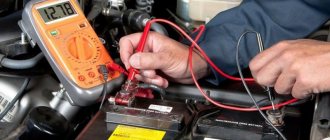
Before you begin repairing electrical equipment, you need to find out the causes of the malfunction. They find a breakdown using diagnostics and use various tools and equipment to find out the cause:
- multimeters, voltmeters, ohmmeters;
- stands for testing generators or starters;
- scanners for computer diagnostics of engines or automatic transmissions.
When diagnosing a battery, use a hydrometer to check the density of the electrolyte in the jars, and use a load fork to determine whether the battery is capable of operating under load. Diagnostics of electrical equipment is not an easy task; in electrical engineering it is often much more difficult to find the cause of a malfunction than to carry out the repair itself. That is why auto electricians are in great demand, and their work is paid hourly.
Car electrical equipment repair
There are many different nuances in the repair of electrical equipment, so in many cases it is impossible to do without qualified auto electricians. Of course, many drivers can repair the starter or generator themselves, or service the battery, but understanding electrical wiring with a large amount of electronics is sometimes beyond the power of even a fairly experienced technician.
It is also not easy to diagnose an engine. Nowadays there are practically no cars whose ignition system is not controlled by an electronic unit. To find out the cause of the malfunction, special car scanners are used, or a laptop is connected to the car’s on-board system. The monitor of the diagnostic device displays errors that exist in the electrical circuit, and various parameters are displayed on the screen. Repair in the ignition system comes down to replacing sensors, restoring contacts in the wires, or replacing the wiring itself.
How to read car electrical diagrams - basic symbols
In order to understand the principle of operation of a device, a knowledgeable person will only need to look at the electrical diagram. Let's look at the main nuances that will help even a beginner understand the circuits. It is clear that not a single device will operate without current, which is supplied through internal conductors. These routes are indicated by thin lines, and their color should match the actual color of the wires.
If the electrical circuit consists of a large number of elements, then the route on it is depicted with segments and breaks, and the places of their connections or connections must be indicated.
The numbers indicated on the nodes must correspond to real numbers. The numbers in the circles show the connections of the wires with a “minus”, and the designation of current-carrying paths makes it easier to find elements located on various circuits. Combinations of numbers and letters correspond to detachable connections. There are special tables that make it very easy to identify elements of electrical circuits. They are very easy to find both on the Internet and in manuals for specialists. In general, car electrical diagrams are quite easy to read; the main thing is to understand the functionality of their elements and follow the numbers.