1200 rub. for the photo report
We pay for photo reports on car repairs. Earnings from 10,000 rubles/month.
Write:
The performance of an injector is its maximum throughput when open (calculated as the supply of the maximum amount of fuel per unit of time). It is measured in cubic cm per minute ([cm³/min] or [cc/min]) or can also be specified as g/min when calculating engine power. Most manufacturers, including Bosch, Siemens, Denso and Delphi, provide American standard injector sizes in pounds per hour (lbs/hr) in their catalogs. The conversion factor is
10.5. Injectors can have a very wide range of performance, for example, for standard Bosch injectors for VAZ engines - 125-137 cm³/min, and nominal ones for Toyota - from 155cc to 430cc. As for forced engines, they can even reach more than 1000 cc/min.
The choice of injector for an injection engine is based mainly on its performance . The stable operation of the engine in different operating modes depends on this indicator. And the quality of fuel atomization (depending on the number of holes), which affects engine power and fuel consumption. In this material we will show how to choose the right injector performance, and also provide a reference table for different manufacturers and cars.
The need to calculate injector performance may arise when tuning the engine or replacing it. After all, correctly selected injectors are the key to efficient engine operation, good dynamic characteristics of the car and fuel economy.
Calculation of injector performance
The standard pressure that most injectors are designed for is 3 Bar. However, if you change the pressure in the fuel system, the fuel flow passing through the injector will automatically change. This is the simplest method to increase its productivity.
First, let's define the concepts. The static performance of injectors is the amount of fuel that flows through a fully open channel per unit of time at a certain pressure. The unit of measurement for this quantity is grams per minute (g/min). In order to convert values from g/min to cc/min, you must use the density of gasoline, which depends on the octane number. So, for A76 - 0.730 g/cm³, AI92 - 0.748 g/cm³, AI95 - 0.758 g/cm³, AI98 - 0.780 g/cm³. Manufacturers give the indicated values in the tables for a pressure of 3 kgf/cm², unless other conditions are indicated, and the fuel density
0.755 g/cm³ (average under normal conditions).
When selecting an injector based on performance, it is necessary to choose a model that will be 10.15% more than the calculated value. In this case, it is desirable that its dynamic range, that is, the opening time, be minimal, and the linear range of operation be as wide as possible. It is also necessary to choose a nozzle with the maximum number of holes. The more there are, the better. If there are many holes in the injector, this increases the dynamic characteristics of the car and also reduces fuel consumption.
As for the dynamic characteristics of the injector , this definition refers to the delay time for the opening of the injector at a given voltage in the vehicle’s electrical network. This value must be adjusted using the computer for specific operating conditions. In addition, it will work differently and under different engine operating conditions.
Nobody changes anything from a good life in VAZ engines, especially in the fuel system. If the question arises about which injectors are best to install on the VAZ-2114, it means that the old ones have expired and they need to look for an adequate replacement. Since the car plant does not offer a wide selection of injectors, the task is simplified. However, there are some nuances that you need to know in order to choose the right injectors.
Checking the performance of injectors and their assembly
Injectors installed on one diesel engine must have the same injection start pressure, as well as the amount of lift of the nozzle needle, atomization quality and productivity. Otherwise, the diesel cylinders will work unevenly, i.e., the power produced by individual cylinders will not be the same. The latter leads to uneven operation of the diesel engine, rapid wear, loss of power and deterioration in efficiency. Therefore, when checking, the injectors are equipped with the same parameters.
The performance of an injector is characterized by the amount of fuel injected into the atmosphere (into a measuring vessel) when it is driven by one section of the pump, which is adjusted to full flow and operates at a speed corresponding to the maximum engine power.
Productivity depends on: injection pressure, needle lift, hole diameter and spray needle pin. Therefore, before checking the performance, the nozzle is adjusted to the injection start pressure, the amount of needle lift and, if necessary, thoroughly washed and cleaned.
The performance of the injector is determined by measuring fuel consumption on a special adjustment stand SDTA-1 or on a stand KO-1608 with an operating fuel pump, then the performance of the tested and reference injectors is compared. The deviation of the performance of the tested nozzle from the standard one is allowed by 1 - 1.5%. If the deviation is greater, the atomizer-needle pair is replaced if it is impossible to restore normal performance by washing, cleaning (in particular, for the KDM-100 diesel injector), and adjusting the needle lift value (0.20-0.25 mm).
The performance of the reference injector is set based on the rated performance of the pumping element given in Table 9.
Checking and adjusting fuel pumps . In fuel pumps they regulate:
- moment when the regulator begins to operate;
- maximum flow and flow rate of fuel supply by pump sections;
- fuel supply at minimum pump shaft speed;
- injection start point;
- limitation of differential speed.
In addition to the above adjustments, the fuel pump is checked for: fuel injection pressure in the low-pressure lines, the tightness of the plunger-sleeve and check valve-seat pairs, the hydraulic resistance of the high-pressure fuel lines and the performance of the booster pump (pump). All these checking and adjustment operations are carried out in a strictly defined sequence. But in practice, it often becomes necessary to repeat one or more adjustment operations. This is explained by the fact that a change in one adjustment necessitates additional adjustments in another. An important final operation for checking and adjusting fuel equipment is installing the fuel pump on the engine, including the associated checking and sometimes adjustment operations.
The technique for checking and adjusting fuel pumps type TP-8.5X Yu and diesel pumps KDM-100 is different. Double-plunger fuel pumps 2TN-8.5X10, which are a two-section model of the 4TN-8.5X10 pump, as well as pumps of the TN-8.5XYu type, are checked and adjusted in the same way. Therefore, the technique of checking and adjusting 4TN-8.5ХУ pumps and KDM-100 diesel pumps is considered separately. In addition, the features of checking, adjusting, as well as installing other pumps and their regulators on diesel engines are separately explained.
The laboratory for testing and adjusting fuel equipment is equipped with special instruments and stands. Let us first consider the structure and operation of the main laboratory equipment used in adjusting pumps.
The KP-1640A device (Fig. 13) is used to test the tightness of precision pairs plunger - sleeve and check valve - seat. It consists of a body 10 attached to the table using a stand 2 and a plate 14.
There is a vertical well in the body. A thrust bearing 11 is inserted into it, the upper end of which is carefully processed. The thrust bearing is supported by a rod 12 with a spherical head. The installation head 7 together with the plunger pair being tested is fixed to the body from above. Screw 8 secures the TN-8.5X 10 type pump sleeve in the head, and screw 15 secures the KDM-100 diesel pump sleeve. Before starting pressure testing, open the tank tap, lift the plunger, and then the fuel fills the entire cavity of the liner. Then the plunger is lowered into the sleeve and a rotary lever 5 is installed on its thrust bearing.
The weight of the lever creates a certain pressure in the confined space under the plunger. For plungers with a diameter of 10 mm (KDM-100) this pressure is 16 kg/cm2, and for plungers with a diameter of 8.5 mm - 22 kg/cm2.
Since there is a gap between the plunger and the sleeve, fuel under pressure flows out from this space, and the lever together with the plunger smoothly lowers. At the moment when the plunger approaches its cut-off edge to the outlet hole in the sleeve, the fuel freely leaves the space under the plunger, which is accompanied by a rapid lowering (“reset”) of the lever. By the time the pressure is held, one can judge the degree of wear of the plunger pair; The shorter the pressure drop time, the more the pair is worn out. These indicators are obtained on the KP-1640A device at such a relative position of the plunger and sleeve, when the plunger is rotated relative to the outlet window in the sleeve by 60° from the position corresponding to zero feed in the direction of its increase. To characterize the wear of a pair, technical standards have been established to determine its suitability for further use. In addition, these standards make it possible to group plunger bunks that have approximately the same wear, and when assembling fuel pumps, install complete pairs of the same tightness. The arrangement of pairs is of great practical importance, since plunger pairs that are close in tightness during operation will have approximately the same wear rate, which means that during operation, the pump sections will supply fuel to the cylinders more evenly and, in addition, will require the same frequency of adjustment.
Plunger pairs are divided into five groups based on wear. The first group includes those that hold pressure for 66-41 seconds, the second - 40-21 seconds, the third - 20-11 seconds, the fourth - 10-5 seconds and the fifth - 4-1 seconds. The plunger pairs of the fifth group are so worn out that they are not suitable for further use.
The procedure for checking the tightness of the plunger pair is as follows. At the moment the lever is lowered onto the plunger, the stopwatch is turned on and turned off at the moment of reset. The difference in readings is the time the pressure drops. The experiment is performed at least three times and the average time is calculated. The results obtained are compared with the technical specifications and the precision pairs are grouped into kits for installation on the fuel pump.
The KP-1609A device can be used to check the tightness of the check valve. For this, a simple device is made, shown in Figure 14. It consists of a housing 1, a turnbuckle 4 and a screw 6. The housing is equipped with a fitting, with which it is attached to the nozzle. A hole is made in the turnbuckle to drain the fuel that has passed through the gap between the check valve and the seat. Fuel under pressure is supplied to the cavity of spring 2.
The tightness of the check valve is checked in two tests. First, they check the tightness or tight fit of the locking cone to the seat and the relief belt to the cylindrical surface of the seat, and then check the tightness of only one pair: the relief belt - the cylindrical surface of the seat.
Insufficient tightness of these connections leads to the fact that during operation of the fuel equipment, the normal mode of fuel supply to the diesel cylinders is disrupted, the injector operates with poor cutoff. All this worsens the processes of mixture formation and combustion, causing coking of the nozzle hole of pin II at the injector needle due to fuel droplets on the nozzle. When checking the tightness, the suitability of the pair for further work is mainly determined. If necessary, the tight fit of the locking cone to the seat is restored by lapping.
In both cases, fuel is injected into a closed cavity above the valve under a certain pressure, the only place for which to exit outside is the gaps between the parts of the pair being tested. An indicator of tightness is the time the fuel pressure drops in the steam.
To determine the tightness of the shut-off valve to the seat, it is necessary to use the pressure lever of the KP-1609A device to bring the fuel pressure in the cavity of the check valve to 150 kg/cm2, monitoring it with a pressure gauge. Having stopped pumping, you need to monitor the displacement of the pressure gauge needle, which characterizes the rate of pressure drop. For a working pair, this speed should not exceed 20 kg/cm2 per minute. Otherwise, the pair being tested is either additionally ground in to improve its density, or discarded. The rate of pressure drop is determined using a stopwatch. In case of problems with pressure, the light and sound annunciator on the stand will sound a signal.
To check the tightness of the unloading belt, place a conical washer with a slot for fuel passage under the shut-off valve. The thickness of the washer should be 0.2-0.5 mm. When testing the unloading belt, an initial fuel pressure of 150 kg/cm2 is created. The time of pressure drop from 150 to 20 kg/cm2 should be at least 4-5 seconds. Otherwise, the valve and seat are discarded.
The KO-1608 stand is used for testing and adjusting fuel pumps and regulators. It can be used to test booster pumps and fuel filters. On the cast iron table 2 (Fig. 15) of the stand are fixed: bracket 3, on which fuel pumps of the TN-8.5X10 type are installed, and bracket 15 for the KDM-100 diesel fuel pump. The pump cam shaft receives rotation from the electric motor 21 through the drive mechanism.
From the electric motor pulley, rotation is transmitted by a V-belt to the variator 22, which is designed to continuously change the pump shaft speed. By rotating the handwheel mounted on the worm shaft, the disks of each pulley are shifted. Due to this, the diameters of the circles on which the V-belt is laid change: the diameter of the driving pair decreases, and the diameter of the driven pair increases, or vice versa. Thus, the gear ratio of the variator changes smoothly, and the shaft of the driven pair gradually slows down or accelerates its rotation at constant revolutions of the electric motor shaft.
In this way, you can change the rotation speed from 200 to 900 rpm. A V-belt drive transmits rotation to the shaft of the pump installed on the stand. The shaft rotation speed is controlled with an attached tachometer. A booster pump is used to pump fuel into the test line.
A frame 8 is fixed on the bench table, on the top shelf of which there are holes for injectors 11. On the middle shelf of the frame, aluminum measuring cups 7 are installed to collect the fuel injected by each injector. Fuel is injected into the cavity of the mufflers 9, where it is collected into a stream flowing out through a hole in the bottom of the mufflers. Then it flows into rotary trays 10 and, depending on the position of the handle 6 of the rotary axis, it is directed either into measuring cups or into a common chute. Through the tube, fuel enters the lower tank 2, and from here it is pumped into the upper fuel tank 5 by a booster pump. In cases where, when the pump is operating, it is not necessary to measure the amount (flow rate) of fuel injected by the nozzle, handle 6 is installed so that the trays drain fuel into common gutter
To measure fuel consumption, turn the handle to such a position that fuel from the mufflers is drained into measuring cups. When replacing the silencer muffler, this is taken into account. Next, after a certain time of operation of the stand, the glasses with fuel are weighed and, in order to obtain the net weight of the fuel, the weight of the glasses is subtracted from the total weight. The number indicating the weight of the glass is placed with a core on its body. To reduce the error in measuring fuel consumption, the glasses in the set are selected to be the same in weight (the difference in weight should not exceed 0.2 g).
The fuel line of the stand consists of an upper tank 5, a distributor with a pressure gauge, a filter 4 and a lower tank 1. From the upper tank, fuel flows by gravity to the distributor and then to the booster pump of the pump being tested. The pump pumps fuel into the filter housing 4-, equipped with a valve to remove air from the line. From the distributor, fuel is supplied to the U-shaped channel of the pump. Part of the fuel that passes through the bypass valve returns through the tube to the booster pump.
For installation of the low pressure system of the stand there is a set of tubes with tips and fittings.
The high-pressure line is represented by conventional high-pressure tubes 12 connecting the pump sections to the injectors.
To check and adjust the start of injection, the nozzle is installed in a special socket - the nozzle holder (the KDM-100 diesel injector is fixed in socket 17). For control, use a working or reference nozzle. This nozzle is connected with a high-pressure pipe to one of the pump sections. The nozzle is installed in a horizontal position with the spray towards the disk mounted on the pump shaft.
The disk has windows covered with a metal mesh, and on its rim there is a scale, each division of which corresponds to 1° of rotation of the cam shaft. When checking the injection advance angle, the window grids are covered with grease, and then with the pump running, when the disk rotates with its shaft, fuel is injected from the nozzle directly onto the disk grid. The force of the jet washes away some of the grease from the mesh, leaving a mark on it. The location of the trace determines the injection advance angle and its duration in degrees of rotation of the cam shaft. The stand kit includes three such discs for pumps 4TN-8.5X10, 1TN-8.5XYu and KDM-100. The disk for the 4TN-8.5ХУ pump is installed on the cam shaft instead of a splined bushing, its hub is equipped with a keyway. The disk for the 1TN-8.5ХУ pump is equipped with a hub with a flange, through which it is attached to the pump gear. The disk for the KDM-100 diesel pump is riveted to the drive pulley, and the pulley is attached with special bolts to the pump gear. To ensure proper connection of the pulley to the gear, there is a hole for a set screw on the pulley, and a mark C on the gear.
Currently, instead of the KO-1608 stand, the industry has mastered the production of a new SDTA-1 stand.
The SDTA-1 stand is designed for testing and adjusting fuel pumps and regulators, for checking the performance of booster pumps, as well as for monitoring the tightness and hydraulic resistance of fuel filters. The general view of the stand is shown in Figure 16. The fuel pump is mounted on bracket 11 attached to the stand table.
The pump shaft is connected using a coupling to the drive shaft of the stand. To turn on and stop the shaft, a magnetic starter 1 is used, which controls the electric motor. Handwheel 2 regulates the pump shaft speed using the pointer of a remote electric tachometer. The low pressure fuel line is connected to the distributor (a block of valves controlled by handles). Valve blocks are used when assembling lines for testing various units of the diesel fuel supply system.
An injector connected to the pump by high-pressure fuel lines supplies fuel through mufflers into 8 volumetric flasks with divisions that make it possible to determine the performance of each pump section in volumetric units for a certain period of time or the number of cycles (injections). To set the required number of pump operation cycles, use a special automatic machine, the handle 4 of which with an arrow and scale is placed on the front panel.
The moment of fuel injection by the nozzle is determined using a stroboscopic device, the light pulse of which in the form of a spark filament from lamp 14 (Fig. 17) is fed to a scale with divisions in degrees of rotation of the pump shaft. In this way, the injection moment and the advance angle of each injector are determined. To turn on the pulse, use switches (toggle switches) located on the front panel. To determine the moment 1 of injection of each section, you need to turn on the toggle switch opposite the corresponding nozzle.
The kinematic diagram of the stand is shown in Figure 17. Electric motor 1 with a power of 1.7 kW, 930 rpm transmits rotation through pulleys 2, 3 and 4 to the variator. The variator consists of two pulleys 8 and 9, rigidly mounted on the shaft, and a block of pulleys 7, which can move in the axial direction and change the diameter of the belt for V-belts, as well as the drive gear ratio. The pulleys 7 move as one unit under the action of the manually operated handwheel 5. The variator allows you to smoothly change the speed of shaft 12, connected to the pump shaft, from 120 to 1300 rpm.
Shaft 12 rotates the cam shaft of the drive of the booster pump 10, mounted on a bracket. In addition, a chain transmission from shaft 12 transmits rotation to a two-stage worm gearbox 18, and from it to an automatic machine 17 for setting the number of cycles for measuring fuel consumption. The measurement begins from the moment you press the handle 16, which is connected by a system of levers 13 with the muffler flap 20 of the injectors. After the set number of cycles, the automatic device 27 reversely moves the damper through the same system of levers and stops the supply of fuel to volumetric flasks 19. The latter are mounted on a rotary axis with handle 6 (Fig. 16).
The diagram of the fuel supply system is shown in Figure 18. From the lower tank 1, fuel is supplied by the booster pump 8 of the stand to the upper tank 7 of a constant level. From there it goes to the pump of the pump being tested, and then along the usual path in the pump system. The fuel injected by nozzle 5 enters the muffler with a damper, and then flows into volumetric flasks 6. After counting the amount of injected fuel, the flasks are turned with a handle. The fuel drained from the flasks flows into the lower tank 1.
The stand distributor is equipped with three taps. To make adjustments, the stand is equipped with a set of special tools, which are stored in a drawer of the table.
Checking the performance of the pump section . The performance of the section is characterized by the amount of fuel in grams or cubic centimeters collected in measuring cups during one minute of pump operation at the set pump shaft speed and the full or intermediate position of the rack regulating the fuel supply. To obtain this indicator, turn on the stand, set the pump shaft speed required by the experimental conditions with the variator, and turn on the fuel supply by moving the rack or regulator lever. After the pump has been running for several minutes, start the stopwatch simultaneously with turning the trays to collect fuel into measuring cups or beakers. After a minute, turn off the stopwatch simultaneously with turning the trays to drain fuel into the tank. Then, by weighing or counting divisions along the level in the beaker, the weight or volume of the fuel is determined. The experiments are repeated several times until stable results are obtained and, based on the data of several measurements, the average productivity value is calculated. After each weighing, the fuel from the glass is drained into the tank (through the drain chute). Glasses should not be wiped; fuel residues should be shaken off overturned glasses.
The duration of each experiment is at least 1 minute. However, for greater accuracy of results, especially with a small feed set by a rack, each experiment is extended to 2-3 minutes (based on the capacity of measuring cups or beakers).
To determine productivity, you need to divide the half-weight of fuel in grams by the duration of measurement in minutes.
At the end of the experiments, first turn off the feed by moving the rack or regulator lever, and then, pressing the red button of the magnetic starter, stop the stand.
To obtain correct performance indicators, measurements should be carried out under identical conditions. The amount of fuel in the stand tank is maintained at the same level, since a change in the fuel level by 50 mm has a significant impact on both the operation of the entire equipment and the performance of the section. The fuel must be of the same quality (viscosity) and have a constant temperature of 20° C. The latter affects not only the viscosity of the fuel, but also the condition of the fuel equipment: the dimensions of parts and gaps in matings change, especially gaps in precision pairs. To determine productivity, it is necessary to accurately weigh fuel samples, set the pump shaft speed, and determine the time of the experiment. The injectors must be properly adjusted, and the high pressure fuel lines must be of the same length and constant hydraulic resistance. If inconsistent performance readings are obtained, you must ensure that all test conditions are met.
Checking the performance of injectors is necessary in order to select sets of injectors that are similar in performance.
The performance of the selected section without a nozzle is preliminarily checked and established. In this case, the pump rack is fixed in a position in which the fuel supply through the high-pressure fuel line is equal to the nominal one at a camshaft speed corresponding to the same nominal speed. The nominal values of feed and speed are indicated in Table 9. For example, for an SMD-14A engine with a fuel pump L4TN-8.5xYuT we find in vertical column 4 the nominal speed of 860-870 rpm and in columns 5 and 6 the corresponding performance of the pump element 70 g /min or 83 cm31min with a fuel specific gravity of 0.85.
Then the injectors are connected by fuel lines to the sections of the fuel pump and they are “run in” on the stand for 10-15 minutes at nominal pump shaft speeds and the fuel supply is fully turned on. The performance of all injectors is checked when they are operating from one section of the fuel pump and when connecting the injectors to the section with the same fuel line, in order to eliminate the influence of the characteristics of individual sections and fuel lines.
The kit for installation on one diesel engine includes injectors whose performance deviation is no more than 2.5%.
Adjusting the bypass valve . In addition to determining the performance of the booster pump, filter resistance and checking the general technical condition, it is necessary to adjust the bypass valve. The action of the bypass valve determines the pressure in the U-shaped channel of the pump. Normal pressure ensures an uninterrupted supply of fuel to the plunger spaces at different fuel supplies by the pump sections.
If the booster pump is working properly, the valve bypass pressure may change due to a decrease in spring stiffness. The valve does not have a special device for restoring normal stiffness. However, under operating conditions, when it is necessary to increase the preliminary compression of spring 6 (Fig. 1U), a washer is placed under its base. The bypass pressure then increases. When it is necessary to reduce the pre-compression, you can place additional washers under plug 5 or remove the washers from under the base of the spring. The response pressure is determined with the pump running using a bench pressure gauge. The pressure gauge is included in the low pressure line in front of the valve. Before adjusting the bypass valve, you must make sure that the booster pump, fuel filters and fuel lines are in good working order and meet the technical requirements.
The response pressure of the bypass valve must be checked at rated pump shaft speed and full fuel supply.
The fuel gear pump of the KDM-YuO diesel engine is equipped with a pressure reducing valve instead of a bypass. The response pressure of this valve is set at the factory and is not adjusted under operating conditions. If, when checking the pumps, it is discovered that the valve spring does not provide normal response pressure, it is replaced. Some types of pumps do not have both bypass and pressure relief valves.
Which injectors are better to install on a VAZ-2114
The first, but not the last sign of injector failure is increased fuel consumption.
In addition, detonation, failures when changing engine operating modes, and unstable idling may occur.
For 2020, AvtoVAZ installs several types of injectors and many of them are interchangeable. Today there are several main types - three types of Bosch injectors and three types of Siemens injectors. First, let's look at Bosch injectors.
BOSCH injectors
Their use depends on the engine size and the number of valves. There is no particular variety in VAZ-2114 engines, so there are only the following options:
- Injector BOSCH 0280 158 022. The nozzle is marked black, has a productivity of 1.9644 mg/sec, and operates at a standard pressure of 3.8 atmospheres. Installed on a 1600 cc engine with 16 valves. Works with January 7.2 controller.
BOSCH nozzle: productivity 1.9644 mg/sec
BOSCH nozzle: productivity 1.922 mg/sec
The new injector may have a thicker O-ring and, accordingly, a longer nozzle. The injectors are completely interchangeable. These injectors can only work with the January 5.1 controller.
In addition, you need to know which engine control controller is installed on the car, since January 5.1 and January 7.2 may require injectors of different capacities.
Siemens Deka injectors
There is no certainty with Siemens injectors, since the plant can install injectors of different markings on the same engine. However, there is a clear difference between the injectors for eight-valve and 16-valve engines .
In the first case, the nozzle is single-flame, in the second - double-flame, that is, it sprays fuel onto each of the intake valves separately.
They are marked as VAZ20734 (orange markings) and 20735 (blue markings). On eight-valve engines, a Siemens 6393 nozzle with a thick torch can be used. Its productivity is 1.662 mg/sec, and its operating pressure is 3 atm . Each of these injectors can be installed on a VAZ-2114 engine.
When to change: self-diagnosis
The fuel system of an injection engine has a fairly extensive architecture and faults can only be identified after an accurate diagnosis of each of the system elements. For example, a drop in engine power may be the result of either a malfunction of the injectors, insufficient performance of the fuel pump or a clogged fuel filter.
In addition, jerks and dips, unstable idle and difficult starting, increased consumption, can occur when the injector is simply clogged.
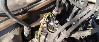
You can check the injectors themselves directly on the engine without removing them. To do this, just start the engine and remove the wires from the connector one by one. If the stability of the engine changes at the same time, the engine starts to oscillate, then the injector is in order. If, when removing the wires from the connector, the stability of the motor does not change, the injector needs to be cleaned or replaced.
Repair and cleaning of injectors
There are several ways to clean injectors.
- mechanical method
- ultrasonic cleaning
- chemical cleaning
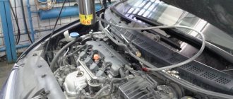
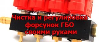
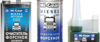
In garage conditions, you can clean it using chemicals. To do this, a special injector cleaner is poured into the fuel tank, which removes a significant part of the pollution during vehicle operation.
.
In order to clean injectors with ultrasound, you need a special stand. The essence of the method is that the nozzles are immersed in a special liquid, in which bubbles are formed under the influence of ultrasonic waves, thanks to which contaminants are removed.
This method is very difficult to implement in a garage, so you will have to go to a service station and pay money for this procedure.
If none of the methods helped, and it was not possible to restore the injector, then it is advisable to replace it.
Fuel injectors are the main element of the injection system. It is worth monitoring and maintaining them in working condition, preventing clogging and periodically doing preventive maintenance, which consists of driving at a speed of 100-110 km/h.
- Self-repair of gasoline engine injectors
- The concept of injector nozzles and the principle of their operation
- Why and when to check injectors
- We look for faults and make repairs
- Diagnostic tool
- Checking power supply to injectors
- Checking the windings
- On-ramp diagnostics
If you are the owner of a car with an injection engine, you should know that for the injection system to work properly, it requires working injectors. You can check the operation of the injectors of an injection engine and troubleshoot problems with their operation yourself; you don’t have to immediately rush to a service station.
The concept of injector nozzles and the principle of their operation
Injectors are required to dose fuel into the combustion chambers of the engine. In the fuel system, they allow gasoline to be mixed with air. Thus, a flammable mixture is formed, which then ignites.
The injectors are:
• Electromagnetic - the valve monitors fuel access and regulates the atomization of the fuel mixture using the electronic engine control unit. There is a valve on the central distribution system in front of the throttle valve.
The principle of operation of the nozzles: an electronic sensor analyzes the volume of air supplied under pressure. The information received by the sensor enters the computer unit for further analysis (for example, engine temperature, air temperature). After this, the computer calculates the size of the volume of air in the fuel mixture required to ensure that the output coefficient of performance (efficiency) from the operation of the engine is as high as possible.
Why and when to check injectors
If you decide to buy a used car, or your car has already driven about 100 thousand km, then you should check the performance of the injectors or replace them.
Replacing injectors (full technology)
Before replacing injectors on a VAZ-2114 of any generation, it is necessary to relieve the pressure in the power system.
To do this, remove the rear seat cushion, open the hatch and remove the contact block from the fuel pump. Now it is de-energized and will not build up pressure.
We start the engine and wait a few minutes until all the fuel in the system is used up. The pressure has been relieved, now you can safely remove the old injectors and replace them with new ones. We proceed according to the following algorithm:
- We de-energize the car by removing the negative terminal from the battery.
