Basic faults
The Lada Kalina speed sensor can easily fail. Every car enthusiast can notice the problem. The main “symptoms” indicating the development of the problem are identified, including:
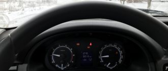
- lack of movement of the arrow (it just lies there);
- the pointer makes sharp jumps;
- the arrow freezes at speed even in the absence of movement;
- The electric power steering fault icon is on.
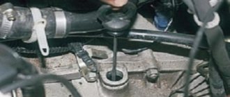
If the speedometer does not work, the most common reason for this phenomenon is a malfunction of the speed sensor. It is located on the gearbox, secured with one screw. There are three main wires connected to it. If it is a Lada Kalina with a 16-valve engine, you can find the device on the washer side. In the version with 8 valves, it is necessary to remove the bellows of the engine air filter.
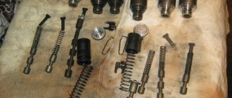
To determine the device number, simply remove it and rewrite the numbers. There is no need to rush into buying a new part; first you need to check all contacts. In some cases, the malfunction is due to oxidation of the wires or damage to the wiring. Perhaps the problem is hidden in the presence of metal shavings or other particles.
Many experts have noticed that the malfunction of the speed sensor on Kalina is associated with problems with the electric power steering. If, after replacing the element, it still does not work, the device may be defective or unsuitable for the vehicle. Therefore, it is necessary to select it according to the assigned number.
How to connect an alarm without auto start
The absence of an automatic engine start function greatly simplifies the installation procedure of the anti-theft system. To connect, the user will need contact elements for the door position as well as the ignition switch.
Preparing the device
To prepare the system, perform the following steps:
- An additional relay and a safety device are installed in the ignition circuit.
- A microprocessor alarm control module is installed.
- The shock controller and transceiver are being installed.
- Pulses from the ignition switch and door positions are connected to the Tomahawk 9010 control module. The light signaling power lines are connected in parallel to the siren.
Working with ignition
If an ignition system blocking relay is used, then when connecting you need to use the electrical diagram:
Engine starting circuit using a blocking relay
Low current circuits and main connector
The installation of low-current power lines of the Tomahawk 9010 anti-theft system is carried out as follows:
- The power in the car turns off; to do this, you need to de-energize the battery.
- The main elements are connected to the microprocessor device. Available in the form of a transceiver with an antenna adapter, an LED, and a sensitivity controller.
- The contact elements of the hood and door sensors are connected to the main block of the control unit.
- The electrical circuits of the engine fluid temperature and pressure controller are connected to the instrument cluster. The contacts of the corresponding sensors are used for connection.
- After the connection is completed, all circuits are checked using the tester.
How to determine that the ds is faulty
The principle of operation of the speed sensor is as follows: there is a certain mark on the gear wheel that generates an impulse using the DS when the wheel rotates. The speed of the vehicle is determined based on the frequency of the received pulses. As the frequency increases, the speed of the machine increases. The signal from the speed sensor, as well as from many others, is output to.
The fact that the DS on the Lada Granta is located low indicates that it is strongly exposed to water, sand and dirt. This is the main reason for its failure. The following symptoms indicate that the sensor responsible for the speed of the Lada Granta car is faulty:
- the speedometer needle is at zero while driving or does not always work;
- unstable idling;
- The speedometer readings do not correspond to reality;
- fuel consumption increases;
- engine thrust decreases.
Please note that unstable engine idle speed and an increase may also be due to a malfunction of the Lada Granta oxygen sensor, which consists of two devices: a control catenary collector located in the upper part, and a diagnostic one installed in the catenary collector behind the converter.
New Lada: Removing the reverse light switch Lada Granta
Functionality, types, design and principle of operation of speed sensors
Speed sensors, regardless of type and design, generate signals that can be sent either directly to the speedometer or to the engine controller and associated electronic control units.
In the first case, the sensor is used only to visually determine the speed of the vehicle. In the second case, the data is used by automotive electronics to control the engine and other systems, and the signal to the speedometer is supplied from the controller. On modern vehicles, the second connection method is increasingly used. Measuring speed using DSA is quite simple. The sensor generates a pulse signal (usually rectangular), in which the pulse repetition rate depends on the speed of rotation of the shaft and, accordingly, on the speed of the vehicle. Most modern sensors produce from 2000 to 25,000 pulses per kilometer, but the most commonly used standard is 6000 pulses per kilometer (for contact sensors - 6 pulses per revolution of its rotor). Thus, measuring speed comes down to the controller counting the repetition rate of pulses received from the DSA per unit time, and converting this value into understandable km/h.
Speed sensors are divided into two large groups:
- Directly driven from the shaft, or contact;
- Contactless.
The first group includes sensors to which torque from the gearbox shaft, axle or transfer case is transmitted through a drive gear and a flexible steel cable (or a short rigid shaft). The sensor contains a device that reads the angular rotation of the shaft and converts it into electrical impulses. Sensors of this type are widely used, since they can be installed instead of a mechanical speedometer drive (which makes it possible to modernize old vehicles without extra costs) and are highly reliable.
The second group includes sensors that do not have direct contact with the rotating shaft. To measure speed with such sensors, an auxiliary device is installed on the shaft - a drive disk or rotor. Contactless devices are becoming increasingly popular; they are also installed on many current models of domestic cars.
All sensors operate on different physical principles. Contact devices most often use the Hall effect and magnetoresistive effect (MRE), as well as optocouplers (optoelectronic pairs). At the heart of non-contact sensors, the Hall effect is most widely used, and MRE is much less commonly used. The design and operating principle of each type of sensor is described below.
Video “dismantling the instrument panel on the Lada Priora”
This video shows the process of removing and replacing the Priora instrument panel (the author of the video is “In Sandro’s Garage”).
- The speedometer needle falls while driving in a Lada Granta - 2 answers
- Lada Granta speedometer failure - 1 answer
- How to wind the speedometer forward yourself? – 4 answers
- Why did the VAZ Granta battery lose power? – 4 answers
- Spontaneous turning on of the VAZ Granta fan - 4 answers
Somewhere the contact is lost.
Check the contact in the connector on the box (on the speed sensor).
Or the sensor is covered. But the check should light up.
How to identify a faulty ds?
The speed sensor is based on the following simple principle:
- The gear wheel of the transmission unit has a special mark that generates impulses through the DS during the rotational movement of the wheel.
- The speed of movement of the Lada Granta car is currently recorded by the frequency of the read pulses.
- As the speed increases, the pulse frequency increases.
- The information is supplied directly by the speed sensor, like from some others, and is displayed on the dashboard.
Due to the unfortunate location of the sensor in question, where is it located? Low and close to the road surface, it becomes subject to dirt and moisture. This causes it to malfunction.
If an element fails, the following factors may indicate this:
- the arrow on the speedometer is located at zero or the device operates periodically;
- the engine runs intermittently at idle;
- the readings on the speedometer do not correspond to the actual speed;
- fuel consumption increases;
- engine thrust decreases.
Here you should pay more attention to the correct identification of this malfunction, since similar symptoms (unstable engine operation during idle and increased fuel consumption) may be present with a faulty LADA Granta oxygen sensor.
Let us remind you that the Lada Grant has two lambda probes. One is the control one (in front of the catalyst), the second is the diagnostic one (behind the converter).
The functions of the first include monitoring and adjusting the composition of the air-fuel mixture, and the second is necessary to register the presence of oxygen in the exhaust gas.
How to tighten the electric power steering rack?
The appearance of a knocking sound in the operation of the electric power steering is associated with the need to tighten the steering rack.
New Lada: Which is better to choose Lada Granta or Vesta (compare)
How to do it right:
- First you need to disconnect the battery; to do this, disconnect the terminals from it. Unscrew the battery mount; to do this, you need to unscrew two more nuts located at the edges. After this, the battery is removed and put aside.
- Then you need to lift the plastic stand, there are four more screws under it, they can also be unscrewed.
- Having done this, it is necessary to move this stand forward until the platform is disconnected from the air filter housing retainer pad. After this, the trim can be moved back, this will provide freer access to the rail itself.
- At the next stage, you will need to crawl your hand under the rail. Directly below it, as shown in the photo, there is a rubberized cap; it will need to be removed, this will allow the key to access the adjusting nut.
- To perform adjustment work, you will need a special wrench to tighten the rack; without it, the adjustment procedure will not be possible. Using this wrench, you need to crawl under the car rail to install the tool in the required hole.
- When adjusting, be careful not to overtighten the rack. If its tightening is very strong, then when cornering the rack will bite, and this, in turn, may affect the safety of movement. The angle of adjustment is always different, it depends on how much the nut is loose, but usually when performing such work the nut is tightened by approximately 30 degrees. This should be enough to get everything right. After the adjustment is completed, it will be necessary to check that this task was performed correctly. That is, you will need to make sure that the steering wheel turns normally to any position all the way and there is no knocking. If the knock remains, then the adjustment continues.
Diagnostic connector type Priora
During the development of “injection” cars, various options for interrogating the ECU (electronic control unit) were developed. At first it was a system for reading codes using a warning lamp. Under special conditions different for different injection systems, the warning lamp began to flash. The master could only write down the rhythm on paper and, checking the table, determine the error.
Subsequently, special diagnostic devices were developed:
- Diagnostic adapters for personal computers.
- Automotive diagnostic scanners.
There are separate articles describing the operation of these devices. But they undoubtedly have one thing in common: a special connector is needed to connect the equipment with the ECU. At first these plugs were made different for each brand of car. There were both round and square. And just paired holes for the dipstick, like on VAG systems. But gradually manufacturers began to think about unification. So, by the early 2000s, the OBD-2 diagnostic connector, now so widespread, appeared.
OBD-2 connector design and its contacts
This connecting plug is made of plastic. The connecting part looks like a trapezoid (see photo). In total, it has 16 female contacts. The countdown starts from the top row, from left to right. The top row is considered to be the wide side of the trapezoid. The following sockets are used for the Priora car:
- Ground (ground), slots 4 and 5.
- Constant “+” 12 Volts - 16.
- Diagnostic socket - 7.
Typically, the equipment is connected to this connector through a special “plug”. The connector plug is of the same shape, but of the male type. Although those who work with various adapters can make connections directly. This is done on some types of adapters that have a separate probe for the K-line. You just need to remember that the “+” and “-” for the equipment must be taken from the battery of the vehicle being tested. Otherwise the communication signal will be incorrect.
Diagnostic connector location
In addition to the fact that these connectors had different shapes, they were located in different places. On the Priora, it is hidden very cleverly. Without knowing where exactly it is located, finding it is very problematic.
Don't let the fog in. The OBD-2 diagnostic connector on the Priora is located on the inner wall of the glove box on the passenger side. As they call it - the glove compartment. On the part that is adjacent to the “beard”. This is clearly visible in the photo. An experienced specialist, a master diagnostician, will connect with a standard connector by touch without any problems. Simply by opening the box and feeling for the nest behind its wall.
For novice diagnostic specialists, it is better to act according to the instructions. In order. That is, open the glove box completely. It will hang on the side plastic guides. Press these thrust plates a little, and the glove compartment will fold back further.
Carefully pull out the side tabs and release the glove box completely. Then access to the diagnostic input plug will be completely free.
Well, then proceed according to the instructions for connecting the available equipment.
Useful video about the location of the diagnostic connector on the Priora:
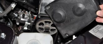
Removing and installing the electronic power steering control unit on the Lada Kalina
For this repair you will need a Phillips screwdriver, the whole job will take at least half an hour, as you will have to. After you have “got rid of it”, you can move on.
- First, unscrew the three bolts securing the plastic trim below the panel:
- After it is removed, the control unit becomes accessible, as shown in the photo below:
- The next step is to disconnect all the plugs and wires, out of three. They are attached as usual using latches and are very easy to remove.
- Now you can unscrew the two mounting bolts with a Phillips screwdriver, which are shown in the photo below:
- After this, we take it by the upper part and lower the electric power steering control unit down, since it is still attached to the plate. It lowers simply, just apply a little effort and it will be almost at the very pedals, it is clearly shown below:
- And there is very little left to do - unscrew the three bolts securing the power steering unit from the plate on which it is installed:
- And holding it from below, we take it out freely. For reference, my 2020 Kalina has a used unit made in Korea. And thank God it’s not ours, the quality of the Korean assembly will be better than that of our craftsmen. At least, I never had any problems with the electric booster in 2.5 years of use.
New Lada: Lada Granta fuel consumption reviews
If replacement is required, install the new module in the reverse order of removal. But it is advisable that you do not have to change this element in the electronics on Kalina, which is quite expensive, around 5,500 rubles according to some official online stores.
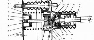
How to remove and check the sensor
BMW 3 series Touring Turik Logbook Checking the outside air temperature sensor
Access from above to the Priora DD is difficult due to the intake module located above it. The easiest way to get to the sensor is from below, first removing the engine protection or at least unscrewing and folding its front part. When working from above, you will have to do everything by touch. In any case, before starting work, it is necessary to disconnect the ground wire attached to the “negative” terminal from the battery.
To remove the crankcase protection, you need to:
- unscrew 5 nuts with a 10mm head;
- unscrew the 2 19 nuts installed on the back of the shield;
- remove protection.
- by pressing the metal latch of the DD connector, disconnect the block of wires going to the controller;
- using a 13mm wrench, loosen the bolt securing the sensor;
- Unscrew the bolt and remove it from the threaded hole, removing the sensor.
- We connect a multimeter to the DD terminals. We set the device to voltmeter mode, choosing a measurement limit of up to 200 mV.
- We take a metal object - pliers or a bolt - and lightly tap it on the DD.
When you tap on a working sensor, the voltmeter will show voltage surges. A faulty DD will not react in any way. A more accurate diagnosis of a removed sensor can only be done using a special stand.
Installation of a new DD is carried out in the reverse order of dismantling. Experts recommend installing a similar Bosch instead of the “native” one. Before going to the store for a new sensor, you should write down the markings of the removed sensor. Tightening the bolt securing it to 13 should be done with a slight force - 10.4–24.2 N m (1.1–2.5 kgf). Tightening too tightly will affect the operation of the sensor.
Problems with engine detonation can occur due to various faults. They are often associated with the operation of the electrical circuit from the knock sensor to the electronic control unit, or with the knock sensor itself. The diagnostic scanner can detect 4 common knock errors - P0325, P0326, P0327 and P0328. For the purposes of this article, we will look at error P0327, which indicates that a low signal level is coming from the knock sensor to the ECU.
List of online stores, addresses of companies providing services
| № | Name | Contacts, address |
| 1. | STO "A1-Motors" | Moscow, st. 1st Dubrovskaya, 13a, building 4, phone: 8 (495) 120-15-38 |
Reviews of companies
- Vasily: six months ago I installed a servo drive on Grant at the A1-Motors service station. The guys did everything quickly and professionally. My recommendations.
- Ivan: after buying the Lada, I replaced the power steering with an electric power steering. I ordered the work from the service station “Auto Service on Sedova”. New equipment, many repair boxes, work professionally.
- Innokenty: comrades recommended installing an electric power steering system. I bought it at the Motel Varshavsky parts store. Good quality, reasonable prices, bonuses when purchasing.
- Vladlen: I drove the power steering for two years and decided to switch to the electric power steering. They advised to buy from Expert-Auto. Six months have passed since installation, no complaints, my recommendations.
- Vyacheslav: I’m leaving my positive review about the auto parts store “Spare Parts on Wheels”. Professional advice, reasonable prices, friendly staff.