Most modern trucks, trailers and buses are equipped with a pneumatic braking system, the operation of which is associated with the interaction of a large number of control and actuating elements. Carrying out a check of the technical condition and instrumental control of the specified system requires diagnosticians to have a good understanding of the general principles of its construction and operation. Therefore, it is advisable to dwell on the design features of this system in more detail.
A pneumatic braking system is a braking system driven by compressed air. In this case, the brake drive means a set of elements located between the control and the brake and ensuring their functional relationship. Where braking is carried out wholly or partly by a power source independent of the driver, the energy stored in the device is also considered part of the drive.
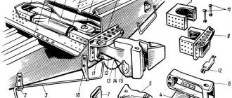
Rice. Pneumatic single-circuit braking system
The drive is usually divided into two functional parts:
- control drive
- energy drive
In this case, control and supply lines connecting towing vehicles and trailers are not considered as parts of the drive.
The control drive is a set of drive elements that control the operation of the brakes, including the function of controlling the required energy reserve.
Energy drive is a set of elements that supply the brakes with the energy necessary for their operation, including the energy reserve used to operate the brake mechanisms.
A brake is a device that generates forces that oppose the movement of a vehicle. The brake can be frictional (when these forces arise as a result of friction of two parts of the vehicle moving relative to each other), electric (when these forces arise as a result of the electromagnetic interaction of two parts of the vehicle moving relative to each other, but not in contact), hydraulic (when the forces arise as a result of the action of a fluid located between two elements of a vehicle moving relative to each other), motor (when these forces arise as a result of an artificial increase in the braking effect of the engine transmitted to the wheels).
Rice. Diagram of the simplest air brake of a car: 1 - receiver; 2 - pedal; 3 - tap; 4 — brake cylinder; 5 - spring; 6 — brake rod; 7 - brake pad
The elements of the friction brake system are called brake mechanisms.
In pneumatic braking systems, the control drive is the pneumatic drive elements, with the help of which signals are sent for automatic or controlled actuation of the energy drive elements. On the control elements of the pneumatic drive (brake valves, valves, regulators, etc.), the input of the control pneumatic signal is always designated by the number 4. The same designation of this signal occurs on functional and block diagrams.
The energy drive in pneumatic braking systems are the elements with the help of which the control drive elements or actuators of the energy drive (brake chambers, energy accumulators, pneumatic cylinders, etc.) are supplied with compressed air. On the control elements of the pneumatic actuator, the input of the supply line is always designated by the number 1. It should be noted that in some cases the control signal can simultaneously perform the functions of the supply line. In this case, on the elements and diagrams of the pneumatic drive, the input of such a signal is still designated by the number 1.
Any pneumatic output signal or effect is indicated on controls or diagrams by the number 2.
In the case where any control elements have several inputs or outputs related to different circuits of the brake system, they are marked with numbers (in ascending order) following the designation indicated above (for example, 11, 12, 21, 22, etc.). P.).
The number 3 on the brake drive elements indicates connection with the atmosphere.
Let's consider the functioning of the pneumatic drive of the brake system and its individual elements using the example of a truck system designed to tow a trailer and, accordingly, a trailer towed by such a tractor.
In order to ensure reliable operation, the pneumatic drive is divided into several circuits, relatively independent of each other. The first of them is called supply and performs the function of preparing compressed air for use in a pneumatic system as a working fluid.
A compressor is an air pump that forces air into the supply circuit and, as a rule, primarily regulates its pressure. The pressure regulator controls the supply of compressed air to the compressor in order to maintain its pressure within specified limits. An air dryer prepares compressed air for use in a pneumatic system.
Its main task is to separate water vapor from the air and filter out various impurities (mainly oil vapor). In modern systems, the dryer combines the functions of separating impurities and regulating pressure, so in such systems there is no pressure regulator as a separate unit. Since most dehumidifiers operate on the regenerative principle, they have a separate receiver with which the regenerative function is ensured.
Some types of pneumatic systems may use an antifreeze guard that mixes a volatile, low-freezing liquid with compressed air to prevent the freezing of water that condenses on the brake drive elements at low temperatures. However, these devices are now rarely used, since modern models of dryers provide compressed air preparation with sufficient efficiency.
Rice. Diagram of the pneumatic drive of the brake system: a - truck-tractor; b - trailer; 1 - compressor; 2 - pressure regulator; 3 - air dryer; 4 - regeneration receiver; 5 - four-circuit safety valve; 6-8 — receivers of pneumatic drive circuits; 9 - additional air consumers; 10 - pressure gauge; 11 — control and alarm indicators; 12 — foot brake valve; 13 — front wheel ABS modulator; 14 — front wheel brake chamber; 15 - check valve; 16 — manual brake valve; 17 - accelerator valve; 18 — rear axle brake force regulator; 19 — rear wheel ABS modulator; 20 — brake chamber with energy accumulator; 21 — brake valve for controlling the trailer brake system; 22, 29 — supply connection heads; 23, 30 — connecting heads of the control line; 24 — electronic control unit for tractor ABS; 25 — ABS warning lamps; 26 — front wheel ABS sensor; 27 — rear wheel ABS sensor; 28, 44 — ABS connecting plug; 31, 32 — air filters; 33 — trailer brake valve; 34 — receiver; 35 — trailer brake release valve; 36 — pressure ratio valve; 37 — front axle brake force regulator; 38 — front axle ABS modulator; 39 — front axle brake chambers; 40 — rear axle brake force regulator; 41 — ABS modulators of the middle and rear axles; 42 — brake chambers of the middle axle; 43 — brake chambers of the rear axle; 45 — trailer ABS electronic control unit; 46 — trailer ABS diagnostic connector; 47 — front wheel ABS sensors; 48 — rear wheel ABS sensors
After passing through the dryer, the compressed air enters the four-circuit safety valve. Main functions of this device:
- division of the compressed air flow into independent circuits
- ensuring the sequential filling of circuits with compressed air after the pressure in one of the circuits increases to the set value
- ensuring the tightness of the remaining circuits of the brake system in the event of depressurization or a large pressure drop in one of them
We recommend: A woman and a car are more than friendship
The four-circuit safety valve distributes air to the following circuits:
- two independent circuits of the tractor's service brake system (I and II)
- the circuit of the parking (emergency) brake system, as well as the supply and control circuits of the trailer (III)
- the supply circuit of the air suspension and other additional air consumers (9 in the figure), for example, the air suspension of the cabin, the driver's seat, the pneumatic hydraulic booster of the clutch, the auxiliary brake system drive (represented in the figure by the engine brake control valve)
Each of the circuits has actuators that implement the final function of directly influencing the brake mechanism, and the circuit of the trailer brake system has connecting heads for connection to the control and supply lines of the tractor.
In circuits I and II of the service brake system, compressed air after the receivers is supplied to the foot brake valve in the upper and lower sections, respectively. Inside this element, either a purely control or a combined (control and at the same time supply) signal is formed, which goes directly (as shown in the figure for the front wheel brakes) or through certain control elements 18 (as shown in the figure for the rear wheel brakes) to the actuators elements of brake systems (14, 20). Additional control elements can be accelerator (relay) valves, brake force regulators that provide the function of accelerator valves, quick release valves, etc. Simple diaphragm brake chambers or combined brake chambers with an energy accumulator can serve as actuating elements.
In circuit III, compressed air is supplied to the manual brake valve of the emergency and parking brake systems, where, as a rule, a purely control signal is generated, which, when sent to the accelerator valve 17 of the emergency brake system, supplies or releases air pressure from the energy accumulator section of the combined brake chamber. Air from the same circuit supplies the brake valve for controlling the trailer brakes. Through this valve, the trailer brake system is powered through the connecting head, and a control signal is also generated as a result of the influence of signals from the brake valves of the working, emergency and parking systems. This signal is supplied to the control line connection head.
Instrumentation and control devices are connected to the brake system circuits. Typically these are pressure gauges indicating the pressure in circuits I and II, or one common pressure gauge. In addition, there are control lights that signal a drop in pressure in the pneumatic drive circuits.
A number of ABS components are connected to the pneumatic system of the tractor, implementing this function for the entire combined vehicle. These include ABS sensors that read the angular speed of the wheels, an electronic control unit that sums and analyzes sensor signals and generates a signal for the output effect, ABS modulators (solenoid valves) that play the role of actuators, a trailer connecting plug, as well as control and diagnostic lamps that provide signals about the technical condition of the system.
The trailer is supplied with compressed air from the tractor through a supply connection head painted red. After passing through the filter and the trailer brake valve, the air enters the receiver.
The pneumatic control signal passes through the control line connection head, painted yellow, and, after passing through the filter, is supplied to the trailer brake valve. Under the influence of this signal, an output control signal is generated in the specified tap, which is adjusted by the brake force regulators depending on the vehicle load. On semi-trailers and trailers with central axles, one brake force regulator is installed. Trailers with staggered axles in the control line of the front axle brake system may have an additional pressure matching valve, which serves to ensure a favorable air pressure ratio between these axles. The adjusted control signal is sent to ABS modulators, which on trailers can also play the role of accelerator valves. Depending on the system design and to meet regulatory requirements, a single modulator on trailers can power the actuators of an axle, a single wheel, or multiple wheels along one side of the trailer. In the pneumatic part of the modulators, the control signal is converted into a signal that activates the actuators (brake chambers). In some cases, trailers use brake chambers with energy accumulators as actuating elements. In this case, there is an additional pneumatic line that supplies compressed air to the energy accumulator sections, and a device for actuating the parking brake system, located outside the driver’s cabin.
Trailer ABS elements include the following devices:
- wheel sensors
- Control block
- pressure modulators with relay valve function
To check the correct operation of the system, a diagnostic connector is used, and a connecting plug is used to provide electrical power to the system and the receipt of control signals from the tractor.
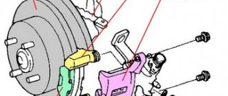
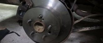
Wheel brake mechanisms, being an integral part of the vehicle's chassis, must ensure the stability of the specified parameters of braking efficiency during operation, have maximum strength and function reliably in any road conditions. Among other things, safety-critical parts must be easily maintained and repaired. Currently, disc brakes, which once became a symbol of progress in the automotive industry, are increasingly being used on trucks and buses.
Increasing reliability and reducing the labor intensity of maintenance are priorities in the development of disc brakes for commercial vehicles.
Let us remind you that the disc brake mechanism, compared to the drum brake mechanism, has less weight, is more compact and stable, and is easier to cool. In addition, smaller gaps between the disc and pads in the unbraked state (0.05–0.1 mm) allow for increased performance and transmission ratio of the brake drive. Finally, more uniform wear of friction materials is achieved as a result of equal pressure distribution over the friction surface.
The lightweight brake mechanism Haldex ModulT (DBT 22LT) is designed for use in axles with a tire diameter of 22.5".
Structurally, the disc brake mechanism is usually placed in a recess of the wheel rim, which requires additional means for heat removal, for example, the presence of internal ventilation ducts in the brake discs and holes in the wheel brake discs. Such measures ensure optimal air flow to reduce brake temperature.
The housings (or brackets, as experts call them) of pneumatic brake mechanisms are either fixed or movable (floating). In the floating caliper design, found on most existing heavy-duty disc brake designs, the brake chamber is mounted on the caliper on the inside of the disc. The caliper has the ability to move together with the brake pad in the caliper along the guide pins. When pressure is applied to the brake chamber, the piston presses the nearest, active pad against the disc. In turn, the bracket, moving in the opposite direction, presses the distant, reactive pad against the disk. To reduce vibration of moving parts, the mechanism is equipped with leaf springs. That is why manufacturers of braking systems have repeatedly made attempts to introduce solutions into the commercial vehicle environment that were previously applicable only in passenger cars. We are talking about brake mechanisms with a fixed caliper, where the pistons are installed on opposite sides of the brake disc. Their main advantage is greater structural rigidity, which means high braking force. Disadvantage: worse heat dissipation.
WABCO MAXX disc brakes are suitable for light, medium and heavy trucks, buses and trailers.
We recommend: Motor oil for two-stroke engines
The problem is solved in different ways. Perhaps the most unusual one was implemented in the ModulD brake mechanism, developed by Haldex. The essence of the idea was as follows. Two brake discs are mounted on a hub with external splines; the possibility of their mutual movement is achieved thanks to a sliding fit. The internal working surfaces of the discs are separated by a brake pad. Two more pads are located on the outer sides of the discs. Due to the displacement of the discs along the splines, the force is evenly distributed over the friction surfaces. A precisely positioned spring mechanism automatically adjusts the gap between the pad and the disc to compensate for wear. The maximum braking torque is 27 kNm. In 2007, some models of Gigant trailed axles were equipped with such mechanisms. It was planned to extend this solution to trucks, but this project was never developed. But the path to perfection continued with disc brakes with a movable caliper. We will talk about them further.
HALDEX MODULT
Today, the priorities in the development of brake mechanisms are compactness, reducing the weight of the brake mechanism, increasing reliability and reducing the labor intensity of maintenance. In 2011, Haldex introduced the new ModulT trailer axle brake. This lightweight but quite effective model replaces the well-known ModulX product on the market. The full name of the new brake mechanism, designed for use on axles with a tire diameter of 22.5”, is DBT 22LT.
The weight of the new product complete with pads is 31 kg. This, according to the manufacturer, is 4.5 kg (or 15%!) less than similar designs offered by competitors today. A significant reduction in the weight of the unit, however, does not call into question the reliability and stability of braking: like the representative of the previous generation of brake mechanisms - the ModulX product, the maximum braking torque with a brake disc diameter of 430 mm is 20 kNm.
Haldex engineers believe that modern braking systems for commercial vehicles now more than ever require specific solutions based on the tightening criteria for automotive products. And as automakers strive to reduce fuel consumption, lightweight designs are here to stay. Using a ModulT disc brake saves 12 kg on each axle. This means that a three-axle semi-trailer equipped with such braking mechanisms will be able to carry an additional 36 kg of payload.
Optimization of the weight and size parameters of the new product was carried out in several ways. Firstly, all parts of the brake mechanism were calculated using the finite element method. Based on these calculations, the originally conceived design underwent significant revision.
Secondly, changes have been made to the kinematic diagram responsible for transmitting force from the brake chamber to the pads. Instead of the usual two-piston design for Haldex products (which means the use of two threaded pusher bushings), it was decided to use a single-piston design. Finally, the ModulT sliding caliper uses just two steel guide pins rather than the previous model's four.
The single-piston mechanism used in ModulT, thanks to the use of a special threaded stop design, ensures uniform distribution of the pressing force of the brake pads to the brake disc and, therefore, better uniformity of wear of the friction material. Among other things, this minimizes the risk of thermal destruction of the pads and disc.
Other important features of the “tashka” include enhanced sealing of the guide pins of the moving bracket, the use of maintenance-free bearings and the use of Teflon coating to improve sliding in the friction pair. The special design of the corrugated boot allows you to reliably protect the threaded bushing of the pressure device from external contamination, which generally helps to increase the durability of the unit.
If we talk about the features of maintenance, in this case all operations are simplified as much as possible. Take, for example, the work of dismantling worn brake pads, for which it is enough to move the clamping bracket that secures them. In this case, no special tools are required, and the applied force is minimal. A wear gauge is available as an option, showing the remaining pad life as a percentage. In its basic version, ModulT is designed for trailed axles with a load of up to 9 tons. There is a separate modification, which is designed for use in trucks and buses with limited installation space within the chassis.
WABCO MAXX
At COMTRANS 2020, WABCO showcased a range of new technologies that improve the safety and efficiency of commercial vehicles. In particular, the guests of the event were presented with the MAXX single-piston pneumatic disc brake, one of the lightest and most effective braking mechanisms for commercial vehicles. The device with a movable bracket is driven by a brake chamber mounted on the mechanism body. To compensate for pad and disc wear, the MAXX brake is equipped with an automatic slack adjuster. A system for monitoring the remaining brake pad thickness is available as an option. Using a potentiometer built into the floating bracket, this equipment measures the stroke of the piston in the threaded bushing and calculates the degree of wear of the friction material. All information enters the vehicle's on-board diagnostic system.
Mounting the diaphragm mechanism directly on the bracket allows for a very compact unit, which means optimal use of the layout space on the vehicle. MAXX disc brakes fit wheels with tire diameters from 17.5 to 22.5" for light, medium and heavy trucks, buses and trailers. This means that the innovative MAXX brakes from WABCO can be used in virtually all wheel sizes used on commercial vehicles around the world.
In Russia, WABCO supplies MAXX brake mechanisms to the assembly line of the Gorky Automobile Plant; new models of trucks produced by the GAZ Group are equipped with these components, in particular GAZon NEXT, which uses a pneumatic braking system.
We recommend: What is the difference between a strut and a shock absorber?
DMITRY MEDVEDEV, General Director of VABKO RUS LLC
The characteristics of a disc brake exceed those of a drum brake. The main advantages of the new MAXX brake are fewer components, impressively light weight, high reliability, increased performance even on bad roads. The MAXX features a new monobloc brake caliper and a reinforced single-piston clamping mechanism that provides increased braking torques of up to 30kNm for maximum driving safety. The patented single-piston brake mechanism transfers force evenly from the pushrod to the pad. The number of parts reduced by half, compared to a two-piston system, made it possible to increase the reliability of the entire mechanism and reduce weight. A balancing plate provides the benefit of ensuring even brake pad wear.
By the way, in terms of maintenance complexity, the MAXX brake is no different from a two-piston system. At the same time, less time is required to check it, and the mechanism for removing and supplying the pads works more clearly.
Description of the working system
You will be interested in: “Mercedes-S-250”: description of models and technical characteristics
How does it work? The principle of operation of the car's braking system is to change the speed of its driving and completely stop it (including in emergency cases to avoid accidents). The system consists of a drive and braking mechanisms. Different types of systems are provided for different vehicles. These are hydraulic and pneumatic.
Description of the hydraulic system
You may be interested in:What is Webasto: how the device works
The principle of operation of a hydraulic brake system is that the pedal acts on the pads using fluid or hydraulics. It consists of the following components:
- main hydraulic cylinder;
- vacuum reinforcement unit;
- ABS or wheel lock control system;
- rear disc pressure control module;
- main brake cylinders;
- hydraulic circuit.
Description of the pneumatic system
The operating principle of a pneumatic braking system is basically the same as a hydraulic one. It consists of an air compressor, which, driven by the engine, pumps atmospheric air into the cylinders. The controller maintains the pressure specified by the parameters.
Air for braking is accumulated in special cylinders or receivers. As it leaves the circuit, it is pumped additionally by the compressor. When the driver presses the pedal, air from the receivers or cylinders flows along the circuit into the brake modules. The latter have special rods that already activate the braking mechanisms. The pads are pressed against the wheel discs (drums). Due to this, the transport begins to reduce speed and gradually stop. After the driver releases the pedal, the air from the system comes back out, and the cycle repeats. Springs return the rods to their original position.
This is basically the operating principle of the KamAZ brake system. This system is often used on trucks due to its efficiency. If the hydraulics need to be checked and fluid added, then the air system requires less attention and does not need constant fluid addition.
Main components of an air brake system
The brake system under discussion is divided into several main components, thanks to which the entire assembly can function properly. Naturally, the list of mechanisms below is incomplete, but, as already mentioned, it will contain the most important things:
- Control drive – this braking system implies the presence of pneumatic drive elements by the control drive. With the help of these parts, automatic or intentional regulation of some parts of the energy drive is carried out, which we will discuss in the next paragraph.
- Energy drive - this mechanism of the pneumatic brake system is a set of elements (parts) due to which the control drive is enriched with pressurized air. Thus, the mechanisms presented in the first two paragraphs (this and the previous one), so to speak, complement each other.
- The brake is the most “central” device! It is here, in this mechanism, that all the forces that resist further movement of the machine in any direction are concentrated. There are several different types of brake:
- Friction - a stopping value appears during the contact of two parts of a vehicle that are moving towards each other.
- Electric - the same friction forces arise under the influence of an electromagnetic field, but the objects do not touch.
- Hydraulic - here again there are two objects moving towards each other, but interaction occurs when the pressure in the liquid between them increases.
- Motor - the braking value increases as a result of the fact that the engine artificially increases the braking effect, while the kinetics is transferred directly to the wheels of the car.
- Compressor - many people have come across a similar device in everyday situations not related to cars. Essentially, it is an air pump that is responsible for ensuring that the brake system receives the required amount of air, as well as regulating the pressure within the system. This mechanism contains a pressure regulator, which is charged with the mission of monitoring and controlling the supply of compressed oxygen to the compressor, so that the values fluctuate within the limits strictly specified by the developers. If the sensor readings are violated, the system may not be able to withstand it and fail, as a result of which there is a chance of a malfunction in the truck’s braking system.
- The compressor also contains an air dryer, the main task of which is to prepare air directly for the pneumatic system, removing from it excess moisture molecules, evaporation from water, as well as other harmful impurities, such as oil deposits, etc.
It is also worth saying that the vast majority of modern dehumidifiers combine, in addition to the main functions, also a regenerating function, which means that their components also include a receiver.
- The braking system can be equipped with another interesting unit, but it is not used everywhere, and is found mainly in serious configurations; it is called an anti-freeze fuse. The principle of its operation and purpose are very simple; in the cold season, this device mixes a special chemical composition into compressed air cylinders. Thus, condensation, which in any case will be present on the system parts, will not freeze and create additional problems.
The design of the car braking system
The composition includes certain mechanisms and drives connected to them. The entire principle of operation of the braking system is based on their clear interaction with each other.
The braking mechanism itself is needed to create the forces necessary to stop or reduce the speed of transport. The element is installed on the wheel hub and works due to friction. The braking mechanism can be disc or drum. The first option is now used much more often.
The brake system includes static and rotating mechanisms. The drums are static, and the pads with special linings rotate. The disc version has a rotating brake disc and a stationary caliper element with pads. These mechanisms are controlled by special drives.
In a braking system, hydraulics are not actually the only system. Thus, traction levers and metal cables are used for parking. Cables are used to connect the rear wheel pads to the lever in the cab. In addition to hydraulics and mechanics, electric drives are also used to control the process of braking and stopping the vehicle.
The hydraulic system can be supplemented by other means. This includes protection against wheel locking, means for directional stability, enhanced emergency braking, and an emergency speed reduction assistance system.
In addition to hydraulics, pneumatic and electrical systems are used. There is a combined type of brakes. This is a pneumohydraulic type, which was previously used on ZIL “Bychok” trucks (at the moment these vehicles are not produced).
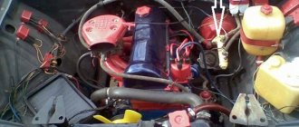
General diagram of the operation of the brake pneumatic system.
When the engine starts, the compressor is switched on at the same time. It takes in atmospheric air and feeds it into the system until operating pressure is reached. The pressure in the system is determined and limited by the pressure regulator. Excess air is directed through the exhaust valve back to the atmosphere. After the pressure regulator, the air is forced through an air dryer. This device is necessary to filter various impurities and retain atmospheric moisture vapor. Dry air ensures trouble-free operation of the system, especially in frosty weather. In most systems, the pressure regulator and air dryer are combined into a common unit, equipped with a small separate receiver. The receiver helps the dehumidifier perform its regeneration function.
After the dryer, the air is distributed by a four-circuit safety valve:
- into two independent circuits of the service brake system, equipped with separate receivers;
- into the circuit of the parking and emergency systems, equipped with an independent receiver (the trailer braking system is also powered through this circuit);
- into the supply circuit of additional air consumers (air suspension and others).
- In addition to dividing the air flow, the valve provides:
- sequential filling of circuits with compressed air.
- if the pressure drops below the permissible level in any one, the others are sealed.
The driver controls the main brake valve via the brake pedal. Through the cavities of the brake valve, air under pressure is pumped into the brake chambers of the front wheels, and through the control elements - into the brake chambers of the rear wheels. The chambers use rods to act on the spreading (compressing) mechanisms of the brake pads. The car is slowing down.
Principle of operation
The operating principle of the braking system is as follows:
- By pressing the pedal, the driver generates some force, which is transmitted to the vacuum unit.
- The force of pressing the pedal increases in the vacuum unit and is transmitted to the main cylinder.
- The cylinder piston acts on the hydraulics and pushes it along the contour of the pipelines. The pressure in the circuit begins to increase, the fluid presses on the pistons of the brake cylinders. They, in turn, press the pads against the discs.
- Increasing the pedal pressure increases hydraulic pressure. Due to the increase in pressure, the braking mechanisms begin to operate. The stronger the fluid pressure, the higher the efficiency of the system.
- Easing the pressure on the pedal returns all mechanisms to their initial position due to a special spring.
To diagnose the pneumatic drive of brake systems, it is necessary to have at least one control pressure gauge and use the control output valves available on the vehicle
Working with one pressure gauge is very labor-intensive, and using only standard control valves makes troubleshooting a number of devices much more difficult.
Therefore, when in-depth checking the performance of a pneumatic drive, you should use a set of control pressure gauges, as well as a set of fittings, adapters and connecting heads that allow you to measure the pressure in any line.
First, the serviceability of the lamps and buzzer is checked . When you press the button in the block, the indicator lamps should light up.
The lamps light up if the pressure in the corresponding cylinders is below 4.8...5.2 kgf/cm2. The buzzer works if at least one lamp is on.
Next, after starting the engine, fill the pneumatic drive with compressed air.
At an engine speed of 2200 rpm, a working compressor pumps up the brake system (the lights go out) in 8 minutes.
If the filling time is longer, then the pneumatic drive may be leaking, the filter in the regulator is dirty or frozen, or the valves in the compressor are faulty.
If the cylinder-piston group is worn out, then, having low performance, the compressor, together with air, will supply oil to the pneumatic drive, which accumulates along with condensate in the cylinders and is discharged from the pressure regulator.
When the pressure in the system reaches 7.0 ... 7.5 kgf/cm2, the pressure regulator is activated, and air from the compressor continuously exits through the atmospheric outlet. Press and release the brake pedal several times.
The pressure in the pneumatic drive will decrease to 6.2 ... 6.5 kgf/cm2.
The unloading valve in the pressure regulator will close, and the compressor will again increase the pressure in the pneumatic drive to 7.0 ... 7.5 gf/cm2.
The opening and closing pressure of the valve in the pressure regulator is monitored by a two-pointer pressure gauge in the cabin or by a pressure gauge connected to the control valve on the condensation bottle.
The air pressure in the pneumatic drive must be adjusted using the screw on top of the pressure regulator.
Deviations in the operation of the pressure regulator: a sudden release of air during the filling of the system, opening of the valve at low or high pressure and the impossibility of adjusting it indicate a malfunction of the device and the need for repair.
Check the pneumatic brake actuator for leaks
When the compressor is not working and consumers are turned off (the brake pedal is released, the parking brake is on), the pressure drop during 30 minutes of testing should be less than 0.5 kgf/cm2.
With consumers turned on (brake pedal pressed, parking brake off), the pressure drop during 15 minutes of testing should also be less than 0.5 kgf/cm2.
To check the operation of the safety valves, connect a pressure gauge to the control valve on the parking brake bottle.
Bleed the air from the front axle cylinder using the condensate drain valve.
In this case, only the upper arrow of the standard pressure gauge should show the pressure drop.
The pressure in the rear bogie and parking brake tanks should not change.
If the pressure decreases in the rear bogie cylinders, then the triple safety valve is faulty, and the drop in pressure in the parking brake cylinders indicates a malfunction of the double or single safety valve (depending on the layout of the pneumatic actuator) feeding this circuit.
In order to check the serviceability of the pneumatic drive of the service brake , you need to attach pressure gauges to the control valves on the pressure limiter and on the back of the frame above the rear axle.
The readings on these pressure gauges correspond to the pressure in the front brake chambers and the rear brake chambers.
When you press the brake pedal all the way, the pressure on the two-pointer pressure gauge should decrease by no more than 0.5 kgf/cm2 (air from the cylinders entered the brake chambers and the pressure dropped), the pressure in the front brake chambers should increase to 7.0 kgf/cm2 cm2 and become equal to the readings of the upper scale of the pressure gauge in the cabin.
The pressure in the rear brake chambers also increases to 2.5 ... 3.0 kgf/cm2 for an empty car.
If you raise the vertical rod of the brake force regulator drive up by the amount of static deflection of the suspension, then the pressure in the rear brake chambers should increase to 7.0 kgf/cm2 (lower scale reading on the pressure gauge).
The static deflection of the suspension when loaded depends on the stiffness of the springs, so for basic models it is respectively: KamAZ-5320 - 40 mm, KamAZ-5410 - 42 mm, KamAZ-5511 - 34 mm.
The drive of the brake force regulator is regulated by changing the length of the vertical rod and changing the length of the regulator lever.
The rod length is set in such a way that when the car is empty and the brake pedal is fully pressed, the pressure in the rear brake chambers is not lower than 2.5 kgf/cm2.
The length of the regulator lever is set constant for this model:
KamAZ-5320—105 mm, KamAZ-5410—105 mm, KamAZ-5511—95 mm. After releasing the brake pedal, the air from the brake chambers should come out without delay and completely.
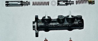
If the nominal pressure (7.0 kgf/cm2) is not provided in the front and rear brake chambers when the pedal is fully pressed, then it is necessary, first of all, to check the correct adjustment of the mechanical drive of the brake valve (Fig. 1).
The drive has two adjusting forks: on the pedal rod and on the intermediate rod. Access to the first adjusting fork is provided when the front end trim is raised.
By shortening the pedal rod, we raise the pedal in the cabin, the full pedal stroke increases, it should be equal to 100 ... 140 mm.
When the pedal is fully pressed, the lever travel of the two-section brake valve is 31 mm.
In operation, there are cars that have a long brake release time, often due to the lack of free play in the brake pedal, which is regulated by the fork on the intermediate link and should be 20...40 mm.
If the maximum pressure in one of the service brake circuits is not ensured, and the pressure in the other is normal, then it is necessary to attach a pressure gauge to the output of the corresponding section of the brake valve: to the top - if the rear bogie circuit is performing poorly, to the bottom - if the front axle circuit is not functioning properly.
Pressure gauges need to be connected to the side (along the vehicle) terminals instead of stop sensors - signals on dump trucks or pipelines going to a two-wire valve on tractor-trailers.
When pressing the pedal, it is necessary to compare the pressure at the outlet of the brake valve and in the brake chambers. When you press the pedal fully, the pressure at the outlet of the brake valve and the pressure limiter should be equal.
The pressure in the rear brake chambers depends on the position of the brake force regulator lever: in the lower position “empty” - 2.5 kgf/cm2, in the upper position “loaded” - 7.0 kgf/cm2.
By comparing pressure gauge readings and knowing the characteristics of the devices, you can easily find out which one is faulty.
When braking with the service brake, you need to check the stroke of the brake chamber rods.
For KamAZ-5320, 5410, 55102 vehicles it is 20 ... 30 mm, KamAZ-5511, KamAZ-53212, 54112 - 25 ... 35 mm. The difference in the stroke of the brake chamber rods on one axle is allowed - 2...3 mm.
To check the operation of the parking brake circuit, it is necessary to connect a pressure gauge to the control valve on the rear of the frame and check the pressure in the energy accumulators.
When the parking brake valve handle is in a vertical position, the car is braked by the force of the springs in the energy accumulators, the pressure in them is atmospheric.
If you move the valve handle to a horizontal position, air from the parking brake cylinders will flow through the accelerator valve into the energy accumulators, the springs will compress, and the car will release the brakes.
The pressure on the control pressure gauge should increase to 7.0 kgf/cm2.
Check the operation of the spare brake by smoothly moving the parking brake valve handle to a vertical position.
When the angle of rotation of the handle is up to 30°, the pressure in the energy accumulators should decrease to 5.0...4.5 kgf/cm2, and the rods of the rear brake chambers should begin to move downwards.
Further smooth rotation of the parking brake valve handle causes a synchronous decrease in pressure in the energy accumulators and extension of the rods.
When the angle of rotation of the parking brake valve handle is 60...70˚, the pressure should drop to zero. If this does not happen, then it is necessary to replace the faulty parking brake valve.
When checking the functionality of the emergency brake release circuit, you need to turn on the parking brake (the pressure in the energy accumulators is atmospheric).
By pressing the emergency brake release valve button, we release air from the service brake cylinders into the energy accumulators.
When the pressure in the energy accumulators reaches 4.8…5.2 kgf/cm2, the flashing light in the control lamp block goes out.
Complete release requires 6...8 seconds. On the pressure gauge in the cabin, the pressure drop when releasing the brakes should be no more than 0.8 kgf/cm2.
After releasing the valve button, the air from the energy accumulators is completely released through the valve into the cabin, and the parking brake is activated.
When the parking brake is applied, a flashing light comes on in the warning lamp unit.
Before checking the auxiliary brake , start the engine and then press the brake valve button.
The engine must stop, since turning the lever on the high-pressure fuel pump will turn off the fuel supply and close the dampers in the exhaust pipes.
The engine stop lever and the damper are driven by pneumatic cylinders.
When braking with the auxiliary brake, air is also supplied to the normally open sensor that controls the solenoid valve on the trailer.
The valve is activated and allows compressed air from the trailer cylinder into the brake chambers.
The pressure in the trailer brake chambers is set to a constant value of 0.6. ..0.8 kgf/cm2, it is adjusted by a screw from the bottom of the solenoid valve.
To check the operation of the devices that control the trailer , it is necessary to attach a pressure gauge to the Palm head of the supply line and open the isolation valve. In this case, the pressure gauge should show a pressure of 6.2…7.5 kgf/cm2.
Then we attach the pressure gauge to the “Palm” head of the control line and open the isolation valve.
When the tractor is released, the pressure in this line is atmospheric.
If you brake the car with the service or parking brake, the pressure should increase synchronously in accordance with the angle of rotation of the parking brake valve handle or the force of pressing the pedal from zero to 6.2...7.5 kgf/cm2.
check the correct adjustment of the two-wire valve by fixing the brake force regulator lever in the “loaded” position.
In this case, the pressure in the rear brake chambers, with a working regulator, will be equal to the pressure in the upper, control section of the two-wire valve.
By comparing the readings of the pressure gauge that measures the pressure in the trailer control line and the pressure gauge that measures the pressure in the rear brake chambers with the regulator lever raised, excess pressure can be determined.
It should be 0.6 kgf/cm2 and regulated at a pressure value of 3-4 kgf/cm2.
When screwing in the screw located inside the two-wire valve, the excess pressure in the control line increases.
Check the operation of the brake light sensor . The sensor contacts should close and turn on the brake lights when the pressure in the trailer control line is 0.1…0.5 kgf/cm2.
To check the operation of the brakes on a single-line drive, it is necessary to attach a pressure gauge to head “A” of the single-line line and open the isolation valve.
When the tractor is released, the pressure in this line should be within 4.8. ..5.3 kgf/cm2. This pressure is adjusted by a screw on the bottom of the single line valve.
When braking with a service, parking or spare brake, the pressure in the single-line line should decrease with full braking from 4.8...5.3 kgf/cm2 to zero.
To check the brakes on a trailer, you must connect pressure gauges to the test outlet valve to check the pressure in the rear brake chambers and to the test outlet valve on the trailer tank.
When trailer brakes operate via a two-line drive, the pressure in the cylinder should be 6.2...7.5 kgf/cm2.
When braking a trailer with a service or parking brake, the pressure in the brake chambers increases from 0 to 3.0 kgf/cm2 if the trailer is empty.
When the regulator lever is raised to the “loaded” position, the pressure should increase to 6.2...7.5 kgf/cm2.
When the solenoid valve is turned on, the pressure in the brake chambers is set to 0.6..0.8 kgf/cm2.
After releasing the brakes, the compressed air must be released into the atmosphere completely, without delay.
To transfer the trailer to work with a single-wire drive, it is necessary to close the disconnect valves in the supply and control lines of the tractor.
As soon as the isolation valve in the supply line closes, the compressed air from the trailer cylinder will exit through the equalizing valve in the air distributor and then through the valve into the atmosphere.
The pressure in the trailer cylinder should drop to 4.8 ... 5.3 kgf/cm2, and after this the trailer brakes should turn on.
The pressure in the single-line line must be equal in value to the pressure in the cylinder. If these values are not equal, then the closing pressure of the equalizing valve should be adjusted with the screw on the air distributor.
Connect the trailer via single-wire drive.
When braking an empty trailer, the pressure in the brake chambers must be at least 3.0 kgf/cm2, and with the regulator lever raised it will increase to 4.8 ... 5.3 kgf/cm2.
If, according to the results of the check, the pressure values at the control points correspond to the specified values, the pneumatic drive of the brake systems of the tractor and trailer is serviceable and operational.