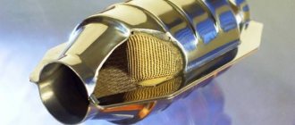
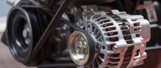
Almost every car owner is familiar with the operating principle of a car compressor. It’s not enough to just watch videos and read specialized forums; you also need to understand all the intricacies of its work. The design of a car tire compressor is quite simple; this device is designed to inflate them.
compressor set
Every car owner needs to purchase it, since tires tend to deflate during the operation of the vehicle. You need to approach your choice very responsibly and not focus solely on the cost of the device. Before purchasing, be sure to familiarize yourself with all the characteristics that the compressor must meet.
Motor-compressor EK-4B for subway cars
The EK-4B motor-compressor is designed to produce compressed air on the car and pump it into the main tank for the purpose of accumulation.
It is installed under the car in its tail section in the area of the second bogie and is attached to special brackets of the body frame using three bolts using rubber-metal shock absorber bushings.
Rice. 2.10. Compressor. General view and basic components
It consists of three main components - an electric motor (1), a compressor (3) and a gearbox (2). The center line of the motor-compressor shafts is located across the car body, and the electric motor is attached to the compressor housing (crankcase) using six M16 bolts. The compressor crankcase, cast from gray cast iron, is the part on which all other components are mounted. Access to the housing is through windows covered with lids. The connecting link between the electric motor and the compressor is a two-stage gearbox.
Rice. 2.11. Compressor operation
Automotive compressor design
It is important to always maintain tire pressure at a certain level so that the operation of the car is comfortable and safe. These standards are usually specified in the instructions for the machine.
Tire pressure becomes less than the recommended level for various reasons. Tire punctures become a headache for the car owner, as well as the fact that even buying high-quality rubber does not completely protect against the fact that compressed air can sooner or later begin to penetrate the tire walls.
Sometimes it is not possible to go to a service station and check the condition of the wheels in a short period of time and, if necessary, pump them up. Therefore, the purchase of a car compressor (tire pump) will be justified. The design of an autocompressor is very simple. It consists of the following parts:
- Cylinder.
- Pressure gauge with scale.
- The engine that powers the compressor.
The functionality of the selected device will depend on the quality of these parts. The design of the compressor is usually simple and the device is driven by a motor. Today, piston compressors are more popular, which are much more convenient than membrane ones.
In turn, they come in two types: stationary (usually used in car services, they are also often used to slightly deflate the wheels of SUVs while driving off-road), and portable (they are connected to the car, if necessary, through the cigarette lighter or to the battery itself ).
Electric motor
Designed to create torque on the compressor crankshaft.
Rice. 2.12. Motor-compressor engine. Components
The motor assembly consists of the following elements: an electric motor (1), a pressed gasket (2), a small (drive) gear (3), which is fixed on the electric motor shaft with a key (7), a thrust washer (4) and a plate washer (5) , as well as two bolts (6).
The DK-408V electric motor is a four-pole DC commutator machine with a supply voltage of 750 V
power 4.5
kW
and armature (motor shaft) rotation speed 1500
rpm
.
Gearbox
Designed to reduce the rotation speed of the compressor crankshaft when transmitting torque from the electric motor shaft to it while simultaneously increasing the torque on the crankshaft.
Rice. 2.13. Motor-compressor gearbox
The gearbox is made in the form of four helical cylindrical gears. Gear (3) is located on the electric motor shaft and is the driving one, and gear (4) is on the compressor crankshaft and is the driven one. Gears (1) and (2) serve as an intermediate link and are located on a separate eccentric shaft, the axis of which is located below the axes of the two main shafts - the electric motor and the compressor crankshaft. In this case, gear (2) engages with gear (3), and gear (1) engages with gear (4).
The total gear ratio is 3.9.
Notes:
The gear ratio of the gearbox is the ratio of the frequency of the drive shaft to the frequency of the driven shaft, i.e. the ratio of the rotational speed of the electric motor shaft to the rotational speed of the compressor crankshaft.
Subway car compressor
Designed to directly compress incoming air.
According to the design and principle of operation of the motor-compressor:
- piston, with crank mechanism
- with horizontal cylinders
- two-cylinder
- single-row
- air (natural) cooling
- simple action
- single-stage compression
- low pressure
- low productivity
The operating mode is intermittent and short-term with an on-time of up to 50%.
Notes:
Productivity is the amount of air compressed to the injection pressure that the compressor creates per unit of time (l/min).
Main technical characteristics:
- Discharge pressure - no more than 8.2 AT
- Estimated productivity - 700 l/min
- Productivity (effective) - no less than 420 l/min
- Crankshaft speed (nominal) - 385 rpm
- Power consumption (power expended to rotate the compressor crankshaft) - 3.7 kW
- Cylinder diameter - 112 mm
- Piston stroke - 92 mm
- The direction of rotation of the crankshaft (as viewed from the electric motor side) is clockwise
- The mass of the motor-compressor assembly is 313 kg
, of which the compressor together with the gearbox is 104
kg
.
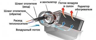
Basic air conditioner malfunctions and their symptoms
- Refrigerant leak. Freon is characterized by high volatility, and therefore gradually disappears from the system at the slightest leak. Even on a sealed system, the air conditioner needs to be recharged every 3-5 years. Most often, a leak occurs when the condenser honeycomb is damaged, due to the natural loss of elasticity of rubber seals (rings on tubes, hose crimps, compressor shaft seal).
- Broken condenser clutch. The normal resistance of a working winding is 4-6 Ohms.
- Faulty wiring, air conditioning relay. The most common occurrence is a banal fuse blown and the formation of oxides on the contacts.
- Condenser clogged. The main sign of a malfunction is low compressor performance, increased pressure in the high-pressure circuit.
- Malfunction of the high/low pressure switch in the system. All modern systems use a combined pressure sensor. Thanks to the PWM signal, the control unit constantly monitors the actual pressure in the system.
- Evaporator clogged. Through a clogged evaporator, less air enters the cabin. Naturally, the air conditioner will not blow cold from the deflectors.
- Sticking thermostatic valve.
- Compressor failure. This happens due to natural wear or operation without oil.
Often the compressor does not turn on after a long period of inactivity. Therefore, if you are wondering whether it is possible to turn on the air conditioner in your car in winter, the answer is definitely yes. Periodic activation allows the oil to disperse throughout the system and lubricate the compressor elements. It is a well-known fact that air conditioning dries the air, and therefore helps prevent windows from fogging up in winter.
Subway car compressor design
The compressor is a crankcase (housing) (Fig. 2.14), in which a double-cranked crankshaft (1) rotates in two ball bearings. Bearing (2) is mounted in the annular bore of the end wall inside the crankcase, and bearing (12) is mounted in a removable cover (8), which is attached to the crankcase from the end through a pressed gasket (10) with four bolts and has a boss in the form of a sleeve for the suspension bolt, as well as a fitting closed with a plug (11), necessary for crankcase ventilation. The inner rings of the bearings (together with the driven gear (4)) are pressed with thrust washers (5), and their bolts (7) are locked with plate washers (6). The outer bearing ring (12) is fixed in the cover (8) using a retaining ring (9).
Rice. 2.14. Crankshaft and support bearings
A connecting rod (21) is attached to each crankshaft journal (Fig. 2.15), having a split head (18), fastened with two connecting rod bolts (15) through gaskets (16) and a sprinkler (17). The bolts are screwed in with nuts (19) and locked with cotter pins (20). When assembling the lower head, guide pins (22) are used. The lower head assembly with filling (23) is the lower connecting rod bearing. A bronze bushing (13) is pressed into the upper head of the connecting rod (14), which is the upper connecting rod bearing for the piston pin, with which the piston is connected to the connecting rod.
Rice. 2.15. Connecting rod components
Each piston (1) (Fig. 2.16) on the outer side has four annular grooves (streams) for four piston rings. Of these, those closest to the piston bottom are intended for compression rings (2), made of cast iron, and the other two grooves are used for oil scraper rings (3), made of nylon or aluminum alloy. One of these rings is installed immediately behind the two compression rings, and the second oil scraper ring is placed on the piston skirt. The required elasticity of the oil scraper rings is ensured by wave spring expanders (6), which are placed in the piston grooves under the rings. The movable connection of the connecting rod with the piston is ensured by installing a piston pin (4), which is fixed by two retaining rings (5).
Rice. 2.16. Compressor piston
Both pistons are placed in the cylinder block (4) (Fig. 2.17), which is attached to the crankcase with six M14 studs (1) through a pressed gasket (2) using two guide pins (3). Nuts (6) with spring washers (5) are screwed onto the studs.
Rice. 2.17. Cylinder block
The cylinder block ends with a valve box cover (17), and the valve box itself (9) is located between it and the cylinder block. The cover and valve box are secured to the cylinder block with six M16 studs (7) through sealing gaskets (8) and (15) made of pressed steel or paronite using a guide pin (16). Nuts (19) with spring washers (18) are screwed onto the studs.
The valve box cover is divided from the inside into two separate cavities - the suction chamber, located at the bottom and ending externally with an inlet fitting (A) and the discharge chamber, located at the top and ending externally with an outlet fitting (B). The cover and cylinder block are equipped with ribs on the outside to enhance heat transfer.
Note:
When the crankshaft rotates, the connecting rod journal moves in a circular motion, just like the lower end of the connecting rod. In this case, the upper head of the connecting rod and the pistons perform a reciprocating movement. The movement that the connecting rod makes as a whole is called flat.
Subway car valve box
The valve box consists of two steel plates (1), between which twelve steel elastic plates (3) are placed in the recesses. Each valve forms a group of three plates - thus, each compressor cylinder is equipped with one block of three suction valves (bottom) and one block of three discharge valves (top). The plate is fixed between the plates using dowels (2). The plates themselves are connected to each other using two screws (4) with nuts (5)
Rice. 2.18. Valve assembly
The operation of the valve box is illustrated by the diagram.
Rice. 2.19. Valve operation
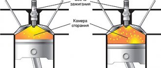
When the compressor is not working (Fig. 2.19), its pistons (3) are motionless, the plates of the suction (1) and discharge (2) valves occupy a free (vertical) position. When a compressor operates, the work of each cylinder can be divided into two strokes - suction and discharge.
When air is sucked into the cylinder, the volume under the piston increases (in this case, the piston in Fig. 2.19 moves to the left), and the plates of the suction valve, pressing against the thrust collar, bend and allow air into the cylinder. At the same time, the discharge valve plates, also bending, are pressed even more tightly against the seat, thereby preventing air from entering the discharge pipe back into the compressor.
When air is pumped, the volume under the piston decreases - compression occurs - in Fig. 2.19 this corresponds to the movement of the piston to the right. The elastic force of the discharge valve plate is designed so that it begins to bend from the seat when the pressure in the cylinder becomes equal to the calculated discharge pressure - at the same time, the suction valve plates are already tightly pressed to their seats. Thus, the action of the discharge valve plates is similar to the action of the suction valve plates.
Using the engine. Advantages and disadvantages
Modern turbojet engines are practically not equipped with centrifugal compressors. Compared to an axial compressor, each compression stage is more efficient, but the overall efficiency is lower. This is explained by the fact that multi-stage centrifugal compressors have a very complex design and large dimensions, which also increases their weight, while multi-stage axial compressors are not a problem. That is why they have found wide application not in aviation, but “on the ground” in power plants used in ventilation systems, on gas transmission lines, etc. Of the aircraft that used jet engines with centrifugal compressors, we can note the HeS 3, which was equipped with the first jet aircraft, the English Power Jets W.1, which was used in the first British fighter, the Rolls-Royce Nene, which later became the prototype of the Soviet RD- 45. The use of such engines was characteristic of the “dawn” of aircraft construction, but now engines with axial compressors are used almost everywhere.
Despite the fact that jet engines are installed on most modern aircraft, they are still far from ideal. They also have disadvantages: high cost and increased fuel consumption. The first drawback is explained by the fact that the manufacture of individual elements of a jet engine requires ultra-strong and heat-resistant materials that can operate at very high pressures and temperatures. As for fuel consumption, it is indeed higher than, for example, that of its closest “relative” turboprop engine, and the cost of flights directly depends on fuel consumption. Therefore, in cases where there is no need to develop supersonic speeds, aircraft are equipped with a turboprop engine, which makes it possible to reduce flight prices. These are mainly passenger and cargo aircraft that fly long distances. But in military aviation, turbojet engines are almost always used, because economy is not as important here as speed.
Subway car compressor lubrication
Compressor oil K-12 (for winter) or K-19 (for summer) is used to lubricate the compressor. Oil volume 2.5 l
is poured into the crankcase through the neck in its upper part. The oil level is determined by the oil indicator, which is a dipstick mounted in a screw plug. It is screwed into a threaded hole located on the rear wall of the crankcase (on the side opposite the cylinder block) and is used to add oil to the crankcase.
Rice. 2.20. Compressor oil indicator
The lubrication of the rubbing parts of the compressor is bubbling, carried out using two sprinklers (2) (Fig. 2.21) installed in the connectors of the lower connecting rod heads. When the crankshaft rotates, these parts of the connecting rods perform a circular motion, while the ribbed surface of the sprinkler, immersed in oil, sprays it as it subsequently moves upward. This creates oil mist inside the crankcase. This oil suspension lubricates the lower connecting rod bearings (1) and all other rubbing parts of the compressor. The gear train is lubricated by two lower intermediate gears immersed in an oil bath.
Rice. 2.21. Compressor sprinkler
Note:
When placing the train in the depot, the driver must check by touch the degree of heating of the compressor crankcase - it should be warm or hot, but not burning his hand. You should check the reliability of the motor-compressor mounting and the condition of all its components. It is also necessary to pay attention to the integrity of the two safety cables that encircle the motor-compressor from below and serve to prevent it from falling onto the path in the event of a break in the suspension elements.
Determination of compressor performance
Compressor performance is a value equal to the volume of air compressed in a unit time (1 minute). Productivity is divided into theoretical (equal to 700 liters per minute) and effective (equal to 420 liters per minute). The latter is always less than the former due to the presence of dead space in the compressor cylinders, the presence of back pressure in the space under the piston, as well as the elastic resistance of the plate valves, hydraulic resistance during suction and discharge, and friction losses during rotation of the crankshaft.
Note:
Dead space (air cushion) is the free space between the piston crown and the valve box. It is formed due to the fact that the piston in its upper position (the position at the end of the discharge phase) does not reach the valve box - a constant gap remains between them. After injection, the air remaining in the resulting air cushion has a pressure equal to the injection pressure. The higher it is, the longer the piston stroke is required in order to expand the air remaining under the piston to atmospheric air, because Only at this moment does the suction valve open.
Rice. 2.22. Scheme of dead space occurrence
- 1. Determination of performance in operation
To do this, it is necessary, with the MK switched on for the entire train, to detect with a pressure gauge the increase in air pressure in the pressure line during one minute of their operation. This increase must be at least 1 AT
. This suggests that all MKs on the train are operational and have the calculated effective performance:
Q = Vnm x (Pend-Pstart) / t
Here Q is the productivity, Vnm is the volume of the pressure line (420 l
), Pend is the excess pressure at the end of the measurement (1
AT
), Pbeg is the excess pressure at the beginning of the measurement (0
AT
), t is the test time (1
min
).
- 2. Determination of productivity on a separate car
Performed in TR-2 after replacing the valve box or in TR-3 after repairing the MK itself. To do this, it is necessary to close the end valves of the pressure and brake lines on an empty car, connect all the air lines to each other, move the driver's valve handle to the second (train) position and turn on the MK with the doors closed. At the same time, the time of its operation until the air pressure reaches 8 AT
in the pressure and other air lines of the car should be no more than 8 minutes.
- 3. Determination of productivity using the two-reservoir method.
Rice. 2.23. Determination of productivity using the two-tank method
Produced during the manufacture of a new MK, as well as in the case of its repair at the manufacturer. To do this, close all taps, turn on the MK and, after increasing the air pressure in tank I to 8 AT
, open valve 3 completely, and open valve 1 slightly so that the pressure in reservoir I remains constant - 8
AT
.
After this, it is necessary to open valve 2 completely, and valve 3 to completely close. At the same time, the air pressure in reservoir II is monitored - in 1 minute it should increase by no less than 1.5 AT
.
Reasons for decreased effective performance:
- Compressor air filter clogged
- Loose seating of valve plates on their seats
- Broken valve plates or burnt valves
- Wear of piston compression rings
- Breakdown of valve box sealing gaskets
- Leak in the connection of the outlet fitting of the cover with the union nut of the pressure line pipeline.
Motor-compressors, motor-fans and motor-pumps
Motor-compressors and motor-fans e.p.s. DC, differing in purpose, power, characteristics, have many common design elements. All compressor and fan motors are single-commutator, four-pole with series excitation. Series excitation provides the simplest motor switching circuit, large starting torques and high overload capacity. Series excitation motors also have better properties during unsteady equipment operation processes. To increase the stability of operation under conditions of significant voltage fluctuations in the contact network and improve starting characteristics, magnetic systems of motors are usually weakly saturated. The windings of poles and armatures are most often made of copper wire with insulation of classes A, B, H and P.
For motor-compressors, motor-fans and motor-pumps. AC domestically produced three-phase asynchronous traction motors1 are used as a drive: AP81-4, AS81-6, AP82-4,
AS82-4, AE-92-402, AOSV72-6, DOZH42-2, AOM42-2, AOM32-4. They have cast iron (most often) or welded steel frames, in which cores made from sheets of electrical steel are fixed. The core sheets are oxidized or varnished. A two-layer, loop (more often) or single-layer winding is laid in the grooves of the stator core. The winding is highly resistant to vibration and shaking. This is achieved by reliable insulation of the grooved parts of the winding, thorough impregnation of it with thermosetting varnishes and reliable fastening of the heads of the frontal parts of the coils to the bandage rings. The stator cores have reliable locking: the bolted connections are equipped with spring or lock washers that prevent spontaneous loosening of the fastening.
The rotor core is made of sheets of electrical steel, not coated with varnish. Its grooves are filled with either an alloy consisting of 96% silumin and 4% copper, or aluminum. Rotor protective slots together
1 Letters and numbers mean - A - asynchronous, P - increased starting torque, C - increased slip, O - blown, D - engine, F - railway, E-electric locomotive, M-marine, B - with a special shaft The first number after the letters indicates the number of the stator diameter, the second - the number of the length of the stator, the third - the number of poles with end rings forming a short-circuited winding of the squirrel wheel type. The end blades of the rotor serve as a fan that cools the engine. Cast rotor winding cages resist vibration much better than welded copper cages. The rotor core is fitted on the shaft using a press fit with a key. The rotor shaft rotates in ball bearings mounted in cast steel bearing shields. The air gap between the stator and the rotor is made as wide as possible (0.35-0.75 mm).
Cast frames and bearing shields provide greater vibration and impact resistance than welded ones. Welded frames and bearing shields are made from steel 10, 15, 20 or M16C bridge, which ensures the resistance of welds at low temperatures.
Motor-compressors e p s. consist of engines and compressors. The engine and compressor are mounted either in the form of one unit (for example, the DK-406 engine and the E-400 compressor) or on one common cast iron plate (KT-6 and E-500 compressors).
The compressor must always be able to replenish the main reservoirs with compressed air. For reasons of reliability, all electric locomotives are equipped with backup motor-compressors. In the electric sections of suburban railways and subways there is no need for this, since they operate in a composition of several units, which in itself creates a sufficient reserve. In the absence of a backup compressor, the compressor operates with an on-duration factor (DU) of no higher than 0.3, and in the presence of a backup, with a DU equal to 0.5.
Engine power is determined based on the supply <2 of the compressor and the back pressure for which it is designed. To select the type and determine the flow <2 = <2average/PV (here <esr is the average air flow rate in one composition, l/min) of the compressor, you need to know the air consumption in the average or maximum length composition. Air flow is determined in volumetric measurement reduced to a free state, i.e. at a pressure of 0.1 MPa and an average external temperature of zero.
Rated power of DC motor, kW,
bearing the maximum torque at symmetrical and rated voltage to the maximum at an asymmetrical load, equal to 1.2-1.5, /sn - the ratio of the minimum possible voltage to the rated one; — overload capacity of the engine under nominal conditions, equal to 1.8-2.4.
where (2 is the compressor flow, l/min (here <2 = С2с.р/ПВ, <2ср is the average air flow rate in one composition); Рвс and Ряг - pressure of intake and discharge air, respectively; Рк - required power to drive the compressor ; Nnom and /nom are the motor voltage and current, respectively; I is the supply coefficient, taking into account air losses during suction and discharge, for two-stage compressors it is equal to 0.68-0.78, for single-stage compressors - 0.58-0.74; - indicator isothermal efficiency (for two-stage compressors T1iz equals 0.72 and for single-stage compressors - 0.67); 1g)m - mechanical efficiency equal to 0.8-0.85; t|d - efficiency electric motor.
If an asynchronous motor is used to drive the compressor, then the calculated rated power, kW,
^*nom a == ^nc^chAa1 (b-n^n) >
where is the minimum required overload capacity of the engine when operating on eps, equal to 1.3-1.4; Yaa - from
On the e.p.s. Only two TYPES of piston compressors with crankshaft speeds of up to 250 and 800 rpm have become widespread. In the first case, the compressor is connected to the engine by a gear transmission, and in the second, their shafts are connected by a coupling.
Electric locomotives with a nominal air pressure in the main tanks of up to 1.0 MPa are equipped with two-stage compressors, which provide for intermediate cooling of the air in coils or refrigerators. At the same time, compressed air enters the main tanks, the temperature of which is lower than in a single-stage compressor; Volumetric efficiency is also improved. air supply and the energy consumption of the compressor is reduced, which allows reducing engine power.
In electrical sections where the nominal pressure in the main tanks does not exceed 0.8 MPa, single-stage compressors are used.
Rice. 144. Electric motor NB-431P for the compressor of electric locomotives VL10, VL10U, VL11.
1 — brush holder bracket; 2 — collector plate, 3 and 9 — bearing shields, 4 — front pressure washer; 5 - pole core; 6-frame, 7 - armature core; 8 — rear pressure washer; 10 - armature winding, And - shaft; 12 - additional pole coil, 13 - main pole coil; 14 - main pole core
| Index | Electric motor type | |||||
| NB-431 | AE-92-402* | 548A | 110-2135/4 | DK-406A | AOSV-72 6 | |
| Series ep s | I love you, VL10u, VL11 | VL80\ V L 80e, VL80R | ER9M, Estonia9R | ChS41 | ER 2 | ER9P |
| Shaft power, kW | 21 | 40 | 5 | 17 | 6,2 | 14 |
| Voltage, V Rotation speed, | 3000 | 380 | 220/380 | 220 | 1500 | 220/380 |
| rpm | 440 | 1425 | 975 | 2800 | 1050 | 900 |
| Efficiency Winding insulation class | 0,786 | 0,855*2 | 0,8 | — | — | 0,8 |
| stator | A | N | IN | A | IN | IN |
| Weight, kg | 1085 | 390-400 | 310 | 300 | 650*3 | 447*3 |
| *This electric motor is with compressor | also used to drive a fan *2 | soe f = 0.79 | *3 Together | |||
The characteristics of some electric motors (Fig. 144) of compressors are given in table. eleven.
Motor fans consist of motors and fans (Fig. 145) of centrifugal radial (on domestically produced electric locomotives) or axial (on electric locomotives F, ChS2, etc.) design. The radial-type fan wheel is mounted on the end of the shaft 2 of the engine 3, and the fan housing (casing) is fixed on the foundation plate to which the engine is attached. Centrifugal radial fans have welded impellers 5, consisting of a carrier and auxiliary disks, blades and a bushing. The wheel is placed in a spiral snail-shaped casing 6 When the wheel rotates, its blades set in motion the air located between them, the air, under the influence of centrifugal force, enters the casing and then through the outlet 1 into the discharge pipeline.
When air is released into the pipeline, a vacuum is created inside the wheel, which causes an influx of outside air through the suction hole 7. From the side of the wheel pipeline, the pressure necessary to impart speed and overcome the resistance to air movement through the pipes and channels of the ventilation system and inside the traction motors is created. Modern traction engines of electric locomotives require 70-100 m3 of air per minute. Taking into account air leaks, the fan supply, for example, on six-axle electric locomotives should be 500-720 m3/min. Limited space in the body does not allow one fan with such a high flow rate. Therefore, two or three fans are usually installed on electric locomotives to ventilate traction motors.
On DC electric locomotives, fan electric motors also serve as drives for control generators 4.
The engine power is determined by the required fan flow. The initial data are the amount of air (2, required for cooling the equipment, and the pressure R. For one ventilated traction motor d = d'dvYa; I = Yadv + 2YaST + 2 yadin,
where <2'dv is the air flow per traction motor; X is a coefficient that takes into account air leaks on the way to the engine, equal to 1.1 -1.2; Yast and Yadiv are static and dynamic pressure losses in air ducts, respectively.
Based on the found values <3 and R, the fan parameters and its design are selected. Motor shaft power, kW,
P = 0.736M2R/(60t1v 75),
where Т1в is efficiency. fan; for fans of the VRS type No. 8 g)v = 0.45 -b 0.55 and fans of the TsAGI type t|v = 0.5 -g—g- 0.7.
To improve the operating conditions of the motor bearings and the fan wheel, the assembled units are subjected to dynamic balancing in a special installation.
Rice. 145 Electric motor TL-110M with fan Ts13-50 and control generator NB-I10 (or DK-405K) for electric locomotives VL10 and VL10′
For fans of passenger rooms of electric trains, DC motors of type P-11 are used. The motor has two main poles with parallel excitation coils and a stabilizing series winding, which ensures the most stable characteristics, and one additional pole. The engine is designed for a voltage of 50 V and a current of 8.7 A, its rotation speed is 2800 rpm, and the power is 0.5 kW.
The characteristics of electric locomotive fan motors are given in Table. 12.
Motor pumps are installed on e.p.s. alternating current. The main pumps are driven by three-phase asynchronous motors (or single-phase capacitor motors on ChS4 electric locomotives), and the auxiliary pumps are driven by DC motors (usually P-11, etc.), powered by batteries. Asynchronous motors are classified as blown machines and most often have a vertical design without feet, with the free end of the shaft located at the bottom. Asynchronous ones are also used
Rice. 146. Longitudinal section of the electric pump 4TT-63/10.
1 - suction pipe,
2 - nut; 3 — lock washer, 4 — impeller,
5 — guiding apparatus,
6 — plug, 7, 17 — bearing shields, 8 — ball bearing, 9 — retaining ring; 10 — housing, 11 — stator, 12 — rotor, 13 — terminal box; 14 — conclusions, 15 — grounding bolt; 16 — locking screw
Electric motor type
| NB-430A | TL-110M | AP-82-4 | 1A-3432/4 | 1A-2732/4 | |
| Electric locomotive series | VL8, VL23 | VL10, VL10* | V L 60* | ChS2 | ChS4T |
| power, kWt | 37,2 | 53,1 | 55 | 17 | 25 |
| Rated voltage, V | 3000 | 3000 | 380 | 3000 | 220 |
| Rotation speed, rpm | 875 | 990 | 1460 | 1450 | 1800 |
| K.p.d. | — | 0,873 | 0,905 | — | — |
| Insulation class | A | V/p*2 | IN | A | A |
| Weight, kg | 1406* | 1150* | 400 | 930* | 340 |
| *Includes fan | *2 For pole coils | ||||
motors of special design, the frame of which serves as a pump housing. Such units are called electric pumps.
The electric pump (Fig. 146) is designed to pump transformer oil in the cooling system of a traction transformer. Oil from the transformer tank is supplied to the pump impeller, where, under the influence of the resulting kinetic energy, it passes through the channels of the rectifying apparatus and through the annular channel enters the straightening blades of the housing. They straighten the flow and turn it towards the discharge pipe. Under the influence of excess pressure, part of the liquid from the rear sinus of the wheel enters the engine, washes the frontal parts of the stator, lubricates the bearings and returns through the holes in the shaft and fairing to the suction cavity of the impeller. The circulation of oil inside the engine leads to intensive heat extraction from the stator.
⇐Auxiliary machine systems | Electric locomotives and electric trains | Voltage dividers and phase splitters⇒