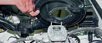
As you know, during engine operation, the cylinder block and engine pistons experience maximum load. This is because these parts operate under harsh conditions of high temperature and pressure, even though the car engine appears to be running smoothly and quietly. During such harsh operation, these parts wear out - the pistons rub against the cylinder walls.
As a result, they acquire a cone-shaped shape, which can negatively affect the safe operation of the engine. These changes may not be noticeable to the naked eye, but this does not mean that they do not exist. So, boring the cylinder block is needed to create/restore this element of the car engine. Let's take a closer look at what boring and honing a cylinder block is, and what are they for?
Why do you need a boring?
Boring is the process of restoring the required geometry, as well as creating the required distance between the cylinder walls and the pistons.
As you know, the cylinder very rarely fails, but sometimes this can happen. Yes, not every cylinder wears out ahead of time, but still, anything can happen with technology. All worn cylinders can be bored. Boring a cylinder block means restoring the quality of the car engine. How to determine that they are worn out and that they need rehabilitation? The first sign of wear is a change in the original dimensions of the piston ring. In the case when the size changes by at least five hundredths of a millimeter, this is a sure sign that the cylinder urgently needs to be bored. The second parameter is the change in size at the points of contact of the piston skirt with the cylinder walls. In this case, even a deviation from the norm of three tenths of a millimeter is fraught with consequences.
As mentioned above, these changes cannot be caught by eye. It is advisable to check the diagnostics and checking of pistons during a routine inspection using a special tool.
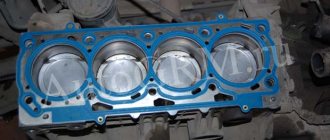
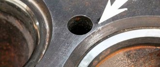
Thus, even with a change of seemingly such minuscule dimensions, it is necessary to resuscitate the system. But, more important, and at the same time dangerous, is the formation of a defect in the form of a step on the walls of the cylinder. It is this defect that accelerates wear not only of the pistons, but also of the ring seat on the piston, and the sound from friction/impact is very noticeable. As a result, vibrations occur in the operation of the machine engine. In addition, the formation of the piston into an elliptical shape prevents the rings from tightly abutting the walls. What can lead to compression failure in the engine, as well as excessive fuel and oil consumption? In the worst case, the rings can fall apart due to constant shock loads, which will lead to the cylinder walls being damaged to such an extent that no amount of boring will correct the defects that have appeared. This means that the cylinder, unfortunately, will have to be thrown away.
So, in order to restore the cylinder block, it is necessary to use the boring method, but for complete restoration it is necessary to create a relative axis and an acceptable arrangement of all surfaces. And for this, a metal processing method called honing is used.
How to bore a cylinder at home
There are several methods for boring a cylinder block with your own hands. The methods are complex, so they will require a lot of free time and effort. Experts advise performing this procedure using a special machine. You must be prepared for the fact that boring with your own hands will not bring noticeable positive results.
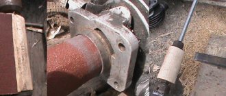
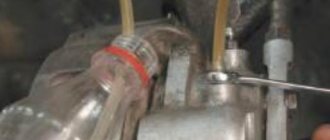
For boring yourself, you may need a very ordinary drill with high power. You need to work in the following sequence:
- Take an old and unnecessary piston and use it to make an attachment for a drill. First you need to make a cut and wrap the piston with sandpaper.
- Place the cylinder on a flat surface and secure it so that it does not move.
- We place the resulting attachment on the drill and turn it on at low speed.
- We bore using up and down movements. It is necessary to ensure that the sandpaper does not fly off the nozzle.
The next method is self-boring using a wooden mandrel.
- You will need to contact a specialist to make a mandrel to the required dimensions.
- Using a jigsaw or saw, a cut up to 1 centimeter deep is cut to install sandpaper.
- You must first buy sandpaper with coarse and fine grains.
- We install the paper and proceed to the sanding process. The paper will need to be moistened with lubricant.
Boring and honing procedure
In order to carry out boring, you need to contact a specialist, that is, take the car to a service station where there is special equipment, namely a machine for boring a cylinder block.
To perform this type of work, a vertical feed machine is used. Considering the fact that this is not a difficult job at all, but its quality directly depends on the newness of the equipment and the professionalism of the machine operator. The most important task is to create a cylindrical shape, this is not only the main task, but also the most difficult. Therefore, before starting processing, it is necessary to calibrate the machine in order to achieve the correct external geometry on the surface.
Also one of the tasks is to remove the taper of the cylinder. It is very important to maintain the minimum change parameters; this can only be done by using a machine for boring the cylinder block, which has an accuracy of up to one hundredth of a millimeter. An important task during wasteful work is compliance with the high requirements regarding the cleanliness of the surface being treated. A high degree of cleanliness is the key to quickly grinding in new parts.
So how does an engine block boring machine work? The workpiece is installed and secured on the working surface of the machine. As mentioned above, a vertical feed machine is used for this type of work. A shaft with an attached cutter, adjusted to the required dimensions, is fed into the hole that needs to be bored. Using a control knob (in old machines) or computer control (inherent in modern equipment), the shaft is lowered down the hole, while aligning it to the same size.
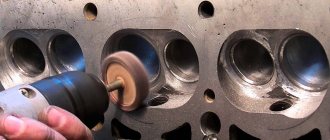
Honing the cylinder block is a necessary procedure after boring work. This process is used to achieve the roundest and smoothest possible hole while maintaining a certain quality of surfaces. In a word, this is the final processing method. The process of honing a cylinder block occurs with constant contact of the tool with the workpiece. The unnecessary layer is removed using grinding agents. This process is sometimes called cross grinding. Because it simultaneously allows for radial and axial movements. To obtain the required steepness of the angles, the master adjusts the rotation speed of the grinding material and the feed speed of the workpiece.
Boring a VAZ cylinder block in St. Petersburg
For VAZ 2106,2107,2108,2109,2114 and similar vehicles, boring the VAZ BC is the only rational option for engine overhauls. We offer high-quality service on mutually beneficial terms:
- fast order fulfillment times;
- urgent car restoration;
- low prices and saving customer time;
- a range of related services;
- guarantee for all work.
The cost of the service depends on the vehicle model and the level of wear of parts. We also offer cylinder honing services. The work is performed on imported machines using diamond bars.
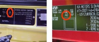
Marking
For boring cutters, a marking system with alphabetic and numeric symbols is used. The first reflect the geometric parameters (2140-0043), the second - the type of material (t15k6 for the option for blind holes). For example, 2140-0042 VK6.
In stores, instead of digital markings, they use the values of geometric parameters, giving dimensions (for example, 20 × 20 × 170 for a carbide model for through holes) and sharpening angle (10 × 10 × 40 VK8 (YG8) 60°, 10 × 10 × 40 mm T5K10 (YT5) 90°). In addition, the markings reflect the type and design of the instrument.
If you find an error, please select a piece of text and press Ctrl+Enter.
The portable machine 2407 is intended for professional boring of automobile engine cylinders at service stations, motor transport enterprises and car services.
Standard equipment:
– Clamps (5 sets of 3 pcs);
– Spring clamps (3 pcs);
Manufacturer: Russia
Model: 2407
Specifications:
| Boring diameter, mm | from 65 to 110 |
| Max. spindle stroke, mm, not less | 250 |
| Spindle rotation speed (nominal), rpm | 200 |
| Nominal feed, mm/rev | 0,05 |
| Cutting depth, mm, no more | 0,3 |
| Returning the spindle to its original position | manual and mechanical |
| Installed drive power, kW | 0,18 |
| Power supply, V/Hz | 380/50 |
| Dimensions, mm | 300x250x720 |
| Installation weight, kg | 50 |
Read also: How to change knives on an electric planer
Design and principle of operation
The installation design includes:
housing, gearbox, electric motor, spindle and control panel (in a separate block).
The housing is the base part for the main components and for attaching the unit to the engine block. The vertical bore of the body serves as a guide for the spindle. There are cuts in the upper and lower parts of the guide, which allows you to select the maximum amount of play between the guide and the spindle using tightening bolts and release bushings.
The spindle consists of a housing in which the head is mounted on two tapered roller bearings. At the top of the spindle there is a nut with a lock nut for adjusting the bearings.
At the bottom of the head there is a socket where the tool holder is installed.
The spindle has a special device for centering the installation along the cylinder axis and consists of a centralizer, three clamps and a spring.
The spindle gearbox is installed on the upper part of the spindle body. The spindle gearbox is used to transmit torque to the spindle head and perform feed.
An adjustable stop is mounted on the spindle gearbox cover to automatically turn off the unit after boring to the set depth.
A gearbox interlocked with an electric motor is attached to the base of the unit. In the gearbox, the rotation speed of the electric motor is reduced and the torque is divided into the spindle rotation drive and the feed drive. Torques are transmitted through the lead screw and the rotation transmission shaft to the spindle gearbox.
During boring, the lead screw, screwing onto the nut, feeds the spindle. The nut is locked using a latch.
At the end of boring, the spindle returns to its original position by rotating the handle. You must first unlock the nut by pulling the locking handle towards you and turning it at an angle of 90 degrees.
The electrical circuit of the installation allows you to return the spindle to its original position, for which the “boring-reverse” toggle switch must be moved to the “reverse” position and by pressing the “start” button, turn on the electric motor for the opposite rotation.
The electrical equipment of the installation consists of an electric motor M and a control circuit, which is mounted in a control unit, which is a portable remote control.
The kinematic diagram of the installation has the following links:
The holes are bored on lathes using boring cutters (Fig. 118). Depending on the type of hole being bored, they are distinguished: boring cutters for through holes (Fig. 118, a) and boring cutters for blind holes (Fig. 118, b). These cutters differ from each other in the main angle f. When boring through holes (Fig. 118, a), the main plan angle is φ = 60°. If a blind hole with a shoulder of 90° is bored, then the main angle in the lead is φ = 90° (Fig. 118, b) and the cutter operates as a thrust-through one, or φ = 95° (Fig. 118, c) - the cutter operates with longitudinal feed as a thrust feed, and then with a transverse feed as a scoring feed.
Boring cutter sharpening angles
In Fig. 118 shows the sharpening angles of boring cutters, which are chosen basically the same as for cutters for external turning, with the exception of the clearance angle a, which for boring cutters usually has an increased value. The size of the clearance angle depends on the diameter of the hole being bored: the smaller the diameter of the hole, the larger the clearance angle of the cutter should be.
Rice. 118. Boring cutters equipped with hard alloy plates: a – through-boring for processing through holes, b and c – persistent-through for processing blind holes
Read also: Equipment for wood processing
Complexity of the operation
Boring is a more complex operation than external turning of surfaces, since:
- when boring, the cross-sectional size of the cutter should be significantly smaller than the diameter of the hole, and the projection of the cutter from the cutting head is slightly greater than the length of the hole being bored (Fig. 119), therefore, when boring a hole of significant length, bending of the cutter is possible, and at high cutting speeds - strong vibrations. Consequently, such cutters do not make it possible to cut chips of large cross-section;
- When boring, it is less convenient to observe the work of the cutter, since cutting occurs inside the hole.
For boring holes with a diameter of up to 70 mm, the innovative turner V.K. Seminsky proposed a special boring cutter equipped with a hard alloy plate (Fig. 120). The cutter shaft has a square cross-section along its entire length, the working part of the cutter is rotated by twisting during manufacturing at an angle of 45° relative to the supporting part. This cutter is characterized by increased rigidity compared to a conventional boring cutter and allows an increase in the chip cross-section by 4-5 times. When working with such a cutter at an increased cutting speed, no vibrations are observed even with a significant overhang of the holder.
Rice. 120. Boring cutter, equipped with a carbide plate, designed by V.K. Seminsky
To increase the vibration resistance of the cutter, the innovative turner V. Lacour proposed a new design of a boring cutter with a carbide plate (Fig. 121). The peculiarity of these cutters is that their main cutting edge is located at the level of the neutral axis of the rod. This arrangement of the cutting
Rice. 121. Boring cutter designed by V. Lakura
edge provides the cutters with a significant increase in vibration resistance and, as a result, makes it possible to work at high cutting speeds and achieve improved cleanliness of the machined surface.
Rice. 122. Mandrel with a cutter for boring a through hole
Installation of cutter
Long holes are bored with cutters fixed in special massive mandrels, the dimensions of which depend on the diameter of the hole and its length. Replacing a solid boring bar with a small cutter inserted into a boring bar provides significant savings in expensive tool material. The method of attaching the cutter to the mandrel depends on its purpose. In Fig. 122 shows a mandrel for boring a through hole; here the cutter is located at a considerable distance from the end of the mandrel. To bore blind holes, the cutter is attached in such a way that it protrudes slightly beyond the front end of the mandrel.
Before boring the hole, it is necessary to set the cutter to the required diameter along the dial of the cross-feed screw, and then bore the hole by hand to a length of 2-3 mm. After measuring the diameter with a caliper or other measuring device and making sure that the size is correct, bore the hole to the remaining length. It is especially important to correctly set the cutter to the required diameter when finishing boring.
The position of the cutting edge of the cutter depends on the type of boring. When rough boring, it is recommended to set the cutting edge at the height of the centers or slightly lower. When finishing boring, the cutting edge must be positioned above the center line by approximately 1/100 of the hole diameter, taking into account that due to the force arising from the resistance of the cut chips, the cutter can be pressed down.
Cylinder boring at home - MOPEDIST.ru
Hi all. Every owner of gasoline equipment has encountered (or will encounter in the future) a problem - cylinder wear. Here they do everything they can - either buy a new cylinder and piston, or buy a new piston and go to a turner. Grandmas pay him, but he is bored... Many turners love blue (alcohol) and the straightforwardness of some leaves much to be desired... I suggest boring the cylinder yourself! It's pretty simple.
General provisions and safety precautions:
The author is not responsible for injuries, accidents during repetition, for “jambs” and defects obtained when trying to repeat the contents of this article.
- If you are under 16 years old, work should be carried out with adults (preferably a male assistant).
- Remember, you are working with rotating parts, do not wear gloves! Work with bare hands. There should be no sleeves on work clothes. Even if there is, roll up your sleeves to at least the elbow.
- What is in the photographs is the author’s work process.
- ANY cylinder can be sharpened using THIS method. The first one that came to hand was taken.
- For the sake of writing this article, a cylinder from the D-6 engine was taken.
- For boring you will need a drill with a power of at least 350 watts. In this article I used a 1050 watt drill.
- The lower the speed, the better. I have 550 rpm.
Please remember that you are working with electrical appliances. Do not allow exposed wires or other defects in the cable network. It is advisable to carry out work outdoors. If the workshop allows it, then you can do it there.
I hope everyone has checked the wires, the condition of the sockets, their workplace, and are ready to continue.
The principle of boring: a guide must pass along the entire length of the cylinder - also known as a “mill” (shaft, cylindrical body). It should be a perfect cylindrical shape. BUT it must be smaller than the current piston that was on the engine. “Rolling” sandpaper onto this shaft will give us a certain “grip” of grinding the metal. That is, the longer the blade, the more the cylinder “eats” from us. Exactly what is needed! To attach the paper to the shaft, we need to make a groove. And fix our sanding cloth in it.
Making a “cutter”
In this operation we will need: a birch log, calipers, a marker, a chisel, a saw, a cylinder (the one we are going to sharpen), a piston (new and old), a rasp (you can use a file), a drill, a long bolt with a nut or a hairpin with two nuts , sandpaper sheets “10”, “6”, “5” and “0” (on a fabric basis - not suitable on paper). There are a few caveats - the stud or bolt must be at least 8mm in diameter. The best solution would be 12mm. Sandpaper is selected independently, depending on the type of boring. It is advisable to go through the “rough process” and bring it “to clean water”, and not to drive the rough one until you are blue in the face. Then fix the finishing one, and buy and select a new piston...
Let's start - measure the sleeve with a caliper:
Let's take an allowance of 10mm and measure it on the already trimmed log:
Let's cut off the result:
Let's outline approximately where we have “more meat”, and set some simple markings there and drill:
Immediately take a larger chisel and chop off the excess “meat”. Shape it into a cylinder.
But the shape of a cylinder will not work, it will turn out something like an oval:
The next step is to tighten the resulting cylinder onto the stud/bolt. Tighten until your teeth creak. When inserted into the drill, tighten until your teeth creak - it will unwind with a bang. If you tighten it harder, it won’t run away. Now secure the drill, make a stop for the chisel, and unwind the cylinder by pressing the gas on the drill. Take technology breaks more often. During breaks, tighten all nuts. If it gets loose, the results could be disastrous...
By substituting a chisel (smoothly substituting a chisel!) we ensure that we first get an oval:
Then the shape will remind us of a cylindrical object:
Later you will get a natural, perfect cylinder. I think there is no need to explain that the fine-tuning was no longer carried out with a chisel, but with a rasp, and later even with a file.
You should end up with a long wooden piston for the cylinder. Only well weakened. Somewhere by 0.3-0.6 mm.
Something like that:
This is an example of relaxation.
Next, we will make a technological cut in a wooden blank:
And you need to make a “latch” for it, that is, a latch. So that the sandpaper does not run away from us somewhere far away. Here I honestly admit that I stepped in the wrong place.
I made it wooden:
And it looked like this:
But when I started refilling, I realized that it didn’t hold well. The answer did not take long to arrive - a 3mm welding electrode worked perfectly as a clamp.
Make a fastener for the drill - it tends to run away from you!
Now let's see how we will have a working area:
And the “relaxation zone”:
Well, we have made our workplace. We can start taking measurements.
Measurements
We buy a new piston, one repair size larger (usually 1 unit) and see how and where it fits (if it doesn’t fit, then it’s still ahead).
We push in different directions to understand where and what is in the way. If the cylinder worked in risky modes, it means it has a huge output. Mine worked with too early ignition, a slightly lean mixture, which gave quite high revolutions.
The cylinder mirror is excellent, but here's the breakdown:
What you see on the cylinder liner is dirt. That is, a lubricant that once was. After removing it, I preserved it for some reason. I don’t know why...
Having measured the piston (even if it goes inside, it jams right in the middle), I realized that it needs to sharpen just a little. If the piston doesn’t fit at all, then yes, let’s see how much grinding needs to be done. Usually in such situations they sharpen 0.1-0.15 mm. I sharpened 0.01-0.07. It is advisable to choose a piston in the store so that it barely enters. Then boring will turn out better because you can pick up the piston even larger and bore it again. In the pictures there is simply a worn-out cylinder that seems to have served its useful life during this repair.
You've been waiting for this for so long, let's start the process.
Boring process
We insert sandpaper into the technological groove and give the drill a short “gas”. After this, the sandpaper tightly envelops our shape. We select the effective length of the sandpaper as follows: measure out a large piece of cloth and screw it completely onto the mold. We put our cylinder on the muffled drill. Doesn't fit? So we unwind it a little, and ruthlessly tear off the extra flap from the sandpaper. An effective thickness is for the cylinder to fit in with a little force, but not too tight. You need to start with “10” grains.
We drove around a little, and we see that our sleeve is gradually increasing in size. The piston slowly begins to climb. A couple of tips:
- DO NOT drive. There is no need to quickly bore. Drive the cylinder slowly, as if imposingly. A little forward, a little back.
- Use the entire workpiece during boring. Don’t stand still, and if it doesn’t go further, then you need to find a defect/jamb while preparing the mold.
- Do not rush to replace the sandpaper with a new one. Sharpen it better than the old one. Even if it is already clogged with chips, clean it and continue working
- Do not set high speed on the drill. The higher the speed, the greater the chance of throwing the cylinder into a landfill.
- Effectively no more than 550 rpm.
- Do not pinch the workpiece while boring. Do not make a sudden forward movement just because the cylinder does not go further (stays in one place). May wrap his hands.
If you follow all the rules, slowly, you can get this result:
Then be sure to rinse the cylinder in gasoline. And then lubricate it with oil (if you are installing it on a vehicle), or lubricate it with grease/lithol (if you are preserving it until the next breakdown).
Now my favorite phrase:
The first time, a young specialist may not get the desired result. This is due to his inattention and deaf ears to my advice. If you follow this article clearly, you can also bore the block on your car. But I don’t know who will need it.
www.mopedist.ru
Geometric characteristics
A boring turning cutter includes a holder used for mounting the tool in the machine, and a working surface. The working surface for cutting into the material is wedge-shaped. It is formed by three angles that together form 90°.
- The primary clearance angle separating the flank and cutting plane reduces friction between the workpiece and the flank. The hardness of materials is inversely related to the value of this angle and directly related to their roughness.
- The point angle separating the back and front surfaces determines the strength of the cutter.
- The main rake angle, separating the rake surface and the plane perpendicular to the cutting surface, determines the degree of deformation of the material being removed.
Dimensions are determined by GOST. Thus, GOST 18882-73 describes turning boring tools with carbide inserts for through holes. GOST 18883-73 defines the parameters of similar tools with inserts made of hard alloys, designed to create blind holes.
GOST 9795-83 describes holder cutters for through holes, designed for oblique and direct fastening.