How do valves work in an engine?
If you have read the article about engine operation, then you know that there are 4 strokes of engine operation:
- inlet,
- compression,
- combustion,
- release.
In modern engines, there are 4 valves per cylinder: two intake and two exhaust - they work in pairs - i.e. two intake valves open simultaneously and two exhaust valves simultaneously (but different timing of intake openings). This is controlled by the camshaft. During the intake stroke, as the cylinder moves downward, a pair of intake valves open so that a mixture of fuel and air can be injected into the cylinder's combustion chamber. Then the valve closes, the cylinder moves upward, and, consequently, the mixture is compressed. When the cylinder reaches its top point, this mixture explodes (triggered by the spark plug in gasoline engines and extreme compression in diesel engines). Now the cylinder, due to the pressure generated by the explosion, moves downwards, and when it reaches the lowest point, a pair of exhaust valves opens so that the exhaust gases are squeezed out by the cylinder when it begins to move up again.
Nothing complicated, right? But what does the valve operation chain consist of, how do they know when to open and close. Alas, but in the era of the smartest computers, this operation is controlled only by some pear-shaped processes on the shaft, which is driven into rotation by the engine crankshaft. This shaft is called a camshaft or camshaft in common parlance.
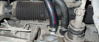
The camshaft comes with a timing belt or chain, which has teeth and is designed to very accurately transmit the revolutions of the crankshaft (which is driven by the engine cylinders) to the camshaft. On the camshaft itself there are so-called cams, egg-shaped “shoots” on the shaft, which push the valves at the right moment. And this is what it looks like:
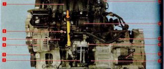
The camshaft, installed in the cylinder block, has small metal pressure cylinders (cams) located above the valve itself and a metal pusher that is located between the valve and the cam. When the camshaft rotates, the cams also rotate, and when their protruding part turns down, it pushes the pusher, which transmits a push to the valve, which opens. And when the cam stops pressing on the pushrod, the valve spring allows it to rise back up to close. This is called an overhead valve system (OHV).
Timing gear characteristics
Influence of selected valve timing on filling
- Resistance in the intake and exhaust tracts, limiting speed and reducing filling at higher speeds. It is determined by the flow sections of valves and pipes, the roughness of the channels, their bending, and settings (inertial charging). With increasing resistance, the peaks of maximum filling shift to the region of lower speed, which limits the power of the internal combustion engine [2].
- Valve timing settings (advanced opening angles of intake and exhaust valves/spools, delayed closing angles). These settings allow you to partially compensate for the resistance of the intake and exhaust tracts, shifting the maximum filling of the cylinders from zero rotation speed (at zero angles) to the frequency specified by the designer. Typically, maximum filling corresponds to maximum torque. The figure shows the curves corresponding to VVT (1), low-speed setting (2), setting at approximately 0.5 maximum speed (3), and high-speed setting (4)[3].
- Possibility of obtaining a compact combustion chamber (minimum dimensions) and low temperature in the area of afterburning of the fuel mixture (spark internal combustion engines). This allows for the least amount of gases in the flame quenching area (which reduces emissions), and improves efficiency[4].
- Residual gas coefficient, possibility of charge turbulence; simplicity, low cost, reliability, dimensions and total mass of parts.
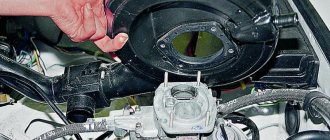
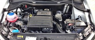
The build process begins
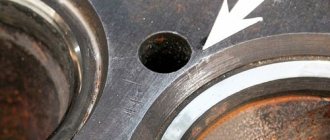
Remove oil from the bolt holes in the block using a compressor or a screwdriver and a cloth. Degrease all adjacent surfaces.
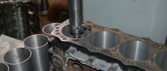
We install a new cylinder head gasket, it is metal. The pistons should not be at top dead center, otherwise when installing the camshafts you can bend the valves one more time. Simply rotate the crankshaft 90 degrees. And after installing the camshafts, first set them according to the marks, and then the crankshaft and everything will be fine.
We put the head in place. We tighten the bolts in the specified sequence in three approaches. First, a torque of 30 Nm, then turn it 90 degrees twice.
We spill clean oil on the valves, hydraulic compensators and rocker arms. Let's put everything in its place.
Around the spark plug wells, as well as around the perimeter, wipe the cylinder head dry to remove any oil. Apply sealant to the valve cover.
And we install it in place, remembering that the piston should not be at top dead center. Tighten the fastening bolts evenly in several passes crosswise from the inside out, in the reverse order of unscrewing. The tightening torque is 10 Nm and turn it 90 degrees. After installation, you cannot start the engine for an hour, as the hydraulic compensators must settle and the sealant must dry.
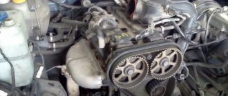
Well, that's all, all that remains is to set the marks, first the camshafts, and then the crankshaft. We install the timing belts, as well as everything that was removed in the reverse order of removal. Fill with antifreeze and engine oil and start the car. Now you can remove and replace the cylinder head, as well as repair it on your favorite Octavia.
With piston valve control
The operating cycle of a two-stroke engine.
From left to right: purging, compression, ignition, power stroke. Gas exchange occurs through the inlet and outlet windows, opened and closed by the piston itself. A gas distribution mechanism with piston control of intake and exhaust (also known as a window gas distribution mechanism) is used on two-stroke engines with crank-chamber scavenging. In it, the valve timing is set due to the opening and closing of windows in the cylinder wall carried out directly by the piston.
The intake window usually opens at a position of the crankshaft in which the piston does not reach 40-60° to the bottom dead center (according to the angle of rotation of the crankshaft), but closes 40-60° after passing it, which gives a fairly narrow intake phase - no more than 130 -140°. On highly accelerated sports engines, the intake window can be opened 65-70° before BDC, which expands the intake phase, but at the same time, engine operation at low and medium speeds becomes unstable, and wasteful fuel consumption increases significantly due to the back emission of the fuel mixture into the atmosphere.
The exhaust window opens approximately 80-85° before the piston reaches bottom dead center, and closes 80-85° after it has passed, which gives the duration of the exhaust phase about 160-165°. The purge phase lasts about 110-125°.
The symmetry of the valve timing during piston control of intake and exhaust is due to the fact that the relative position of the piston and windows in the cylinder wall is the same both during the upward stroke and during the downward stroke. This is a disadvantage, since for optimal engine operation, at least the intake phase must be asymmetrical, which is unattainable with pure piston valve control. To obtain such characteristics, small two-stroke engines with crank-chamber scavenging use spool valve timing or an intake reed valve (see below)
.
In large-volume two-stroke engines (diesel locomotive, marine, aviation, tank) there are either two pistons per cylinder moving towards each other, one of which opens the inlet windows, and the second opens the exhaust windows (direct-flow purge), or through the windows in the cylinder wall only intake and exhaust are carried out using a valve in the cylinder head (valve-slot scavenging), which also achieves more optimal scavenging.
In rotary piston engines, gas distribution control is also usually used by a piston (rotor), which in this case plays the role of a spool.[5]
With spool valve control
The gas distribution mechanism of a two-stroke engine with a rotating disc spool mounted at the rear of the crankcase, a partially open intake port is visible under the spool. Control of gas distribution by a piston valve on a four-stroke engine. Spool valve timing with a rotating spool on a four-stroke engine, each spool served two adjacent cylinders (Itala, 1910s).
In two-stroke engines
Spool gas distribution was used on Lenoir's two-stroke gas engine, considered the world's first commercially successful internal combustion engine (1859). Its gas distribution mechanism with two box-shaped spool valves was completely copied from the steam distribution mechanism of steam engines, and with the help of spool valves both the intake of the gas-air working mixture and the exhaust gases were carried out. However, subsequently the development of two-stroke engines followed the path of using piston (on light engines) or valve gas distribution.
The use of spool valve gas distribution on light two-stroke engines of the modern type (with crank-chamber scavenging) can be traced back at least to the 1920s, but a truly successful implementation of this principle was carried out only in the early 1950s by East German engineer Daniel Zimmermann on sports and racing cars. motorcycles, and then in the 1960s - 70s, similar solutions began to appear on some production motorcycles of the brands Jawa, Yamaha, Suzuki, Kawasaki and others.
On two-stroke engines with spool valve control, a spool driven by the crankshaft is used to control the intake - a rotating disk or cylindrical (crane) type or having a reciprocating movement of the plate type. The spool in one way or another opens and closes the engine intake port, thereby controlling the intake duration. Thanks to this, it is possible to make the intake phase asymmetrical relative to BDC (as a rule, it begins 130-140° before BDC and ends 40-50° after) and increase its duration to 180-200°, thereby improving cylinder filling. Some implementations of spool valve control even make it possible to change the valve timing directly while the engine is running. The exhaust typically continues to be controlled by a piston that opens the exhaust port(s).
For a similar purpose, a petal or diaphragm type valve (Yamaha, etc.) that is automatically triggered by a pressure difference can be installed in the engine intake tract.
In the early 1950s, at the Perm Engine Plant No. 19, under the leadership of V.V. Polyakov, two-stroke five-cylinder star-shaped aircraft engines VP-760, VP-1300 and VP-2650 were developed and produced in a small series with gas distribution mounted in the crankcase by a rotating spool and purge by two-stage pistons in the shape of an inverted letter T (the narrow part is the working part, the wide part is the discharge part), which were intended for use in light aircraft.[6].
Experiments with gas distribution using a rotating spool were carried out in the early 1990s by Lotus in relation to a two-stroke automobile engine with purge from a drive compressor, and, unlike a conventional two-stroke engine with valve-slot purge, fresh air was supplied to the upper part of the cylinder through the spool, and exhaust gases were removed through windows in the lower part of the cylinder (in a conventional engine with valve-slot scavenging, air is supplied through windows in the middle part of the cylinder, and gases are removed through a valve in the cylinder head). The spool had the appearance of a hollow cylinder - a rotor - constantly rotating around its axis - with windows in the walls, inside of which there was also a stator with a longitudinal partition in the form of a hollow cylinder, the rotation of which relative to the rotor, carried out by an electronic system, controlled the valve timing. This gas distribution device made it possible, instead of the direct injection usually used on diesel engines with valve-slot purge, to use a cheaper version of the power system, with a low-pressure nozzle spraying fuel inside the spool, from where the working mixture was blown into the cylinder through the inlet window. This work was completed without results, one of the reasons for which was the sharp tightening of environmental standards in the mid-1990s (Euro-1, Euro-2, etc.), which put an end to the use of two-stroke engines in road transport.
In four-stroke engines
Spool valve valves with box-shaped, piston or rotating valve valves, one way or another connected to the camshaft and opening and closing the intake and exhaust ports, were used on some four-stroke engines, but were not widely used due to a number of difficulties in practical implementation of this principle, in particular, problems with sealing spools, especially those working on the outlet and, therefore, under high pressure of hot exhaust gases.
Gas distribution with a box spool, similar to the spools of steam engines, was used on the world's first four-stroke internal combustion engine, designed by N. Otto (1861), and was quite widely used on low-speed stationary engines of the 19th - very early 20th centuries.
Gas distribution control by reciprocating piston valves is actually standard on steam engines and powerful piston pumps; some designers tried to adapt it to an internal combustion engine, but without much success - moving the valve was very difficult due to the high gas pressure, which created a huge the frictional force between the spool and the walls of the spool box, not to mention problems with gas breakthrough through the seals.
Somewhat greater success fell on gas distribution mechanisms with a rotating (crane) spool. This gas distribution option attracted designers due to its quiet operation compared to conventional poppet valves (the knocking of which during timing operation was a big problem for engines of the early 20th century), the ability to obtain potentially higher throughput compared to valve timing, and simplify timing due to the use of a single spool per cylinder, working both for intake and exhaust, or even one for each pair of cylinders, and also to eliminate from the combustion chamber one of the most dangerous sources of detonation - the exhaust valve (which, again, was very important at the beginning of the 20th century, when the available fuel had a very low octane number).
The first patent for gas distribution by a rotating spool was obtained by the British company Crossley[en] in the mid-1880s. Low-speed gas engines based on it were popular as stationary ones and were produced by this company from 1886 to 1902.
The peak of popularity of this design in automobile engines occurred in the early 1910s, when, following the latest fashion, a number of companies that produced expensive cars presented their versions of spool valve gas distribution, such as Itala (Italy, 1911), Darraq (France, 1912) , later Minerva (Belgium, 1925).
Relatively successful designs of engines with gas distribution using a conical rotating spool were created by the British R. Cross and F. Aspin in the 1930s - 1950s; they were used in racing cars, but never entered mass production, including due to unresolved problems with the seal and lubrication of the spool. In those same years, the German engineer F. Wankel experimented with spool valve gas distribution in collaboration with BMW, DVL, Daimler-Benz, Lilienthal and Junkers, however, without achieving decisive success, he switched to working on a rotary piston engine project, which was very succeeded.
In the 1950s, experimental engines with spool valve valves were built in the USSR based on the serial Moskvich-400 (4-cyl.) and ZIS-120 (6-cyl.) engines, which had valve spool valves installed in the cylinder head and rotating around an axis parallel to the axis of the crankshaft. Compared to lower valve engines, engines with spool valves had better cylinder filling and, accordingly, higher specific power - for example, on the Moskvich engine the increase in power compared to the serial one was 8%. However, at the same time, oil consumption significantly increased due to problems with the spool seal, and the engine operated with noticeable smoke. In addition, at the end of the compression stroke and during the working stroke of the piston, the spool experienced high friction due to the pressure on it of the sealing shoe, which was under pressure from the exhaust gases, which significantly increased friction losses, and on a six-cylinder engine even led to a break in the three-row drive chain Timing belt during testing. It was never possible to provide the required service life for engines with spool valve timing.[5]
Around the same time, the British company Norton produced a number of racing motorcycles with spool valve timing, but in 1954 they completely stopped working in this direction. A type of spool valve is sometimes considered to be sleeve gas distribution, discussed separately below in the text.