Diagram of carburetor 2105, 2107 Ozone and their modifications without forced idle economizer
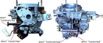
1. Acceleration pump screw. 2. Plug. 3. Fuel jet of the transition system of the second chamber of the carburetor. 4. Air jet of the transition system of the second chamber. 5. Econostat air jet. 6. Econostat fuel jet. 7. Air jet of the main metering system of the second chamber of the carburetor. 8. Econostat emulsion jet. 9. Diaphragm mechanism for pneumatic drive of the throttle valve of the second chamber of the carburetor. 10. Small diffuser. 11. Jets for the pneumatic drive of the throttle valve of the second chamber of the carburetor. 12. Screw – valve (discharge) of the accelerator pump. 13. Acceleration pump nozzle. 14. Carburetor air damper. 15. Air jet of the main metering system of the first chamber of the carburetor. 16. Damper jet of the starting device. 17. Diaphragm trigger mechanism. 18. Air jet of the idle system. 19. Fuel jet for idle system. 20. Fuel needle valve. 21. Carburetor strainer. 22. Fuel fitting. 23. Float. 24. Idle speed adjustment screw. 25. Fuel nozzle of the main metering system of the first chamber. 26. Fuel mixture “quality” screw. 27. Fuel mixture “amount” screw. 28. Throttle valve of the first chamber. 29. Thermal insulation spacer. 30. Throttle valve of the second chamber of the carburetor. 31. Diaphragm rod of the pneumatic drive of the throttle valve of the second chamber. 32. Emulsion tube. 33. Fuel nozzle of the main metering system of the second chamber. 34. Accelerator pump bypass jet. 35. Accelerator pump suction valve. 36. Accelerator pump drive lever.
Car service address: St. Petersburg, Sofiyskaya st., 79
Telephone
Car assistance in ALL DISTRICTs of St. Petersburg and the Leningrad region! 24 hours!
Call or make an appointment at a time convenient for you.
Troubleshooting the VAZ 2107 carburetor
To restore the operation of the carburetor, you should inspect the condition of the components and parts, clean them and adjust them.
After disassembly, it is necessary to wash all carburetor parts and visually check for defects. Particular attention should be paid to the condition of the strainer and jets, which are especially susceptible to clogging, which is the most common cause of malfunction. the VAZ 2107 carburetor jets by blowing them with compressed air.
After cleaning, you need to adjust the carburetor:
- The needle valve is adjusted by bending the "tongue" of the float bracket. When the valve is open, the distance between the lid and the float should be 15 mm, when closed - 6-7 (in the air) and 1-2 (when immersed in a chamber with gasoline).
- To adjust the starting system, simply remove the air filter. With the “suction” extended, the air damper should be open by a third, and the speed should be in the range of 3200-3600 rpm.
- The idle speed should be adjusted when the engine is warm. First you need to achieve maximum speed by turning the mixture quality screw. Then, turning the quantity screw, achieve engine speed within 950-1050 rpm. Finally, use the quality screw to lower the speed by 100 rpm.
Now, knowing the structure and operating principle of the VAZ 2107 carburetor, you can adjust its operation if necessary.
The power supply system of the VAZ 2107 is practically no different from all rear-wheel drive VAZ cars. The only exception is the carburetor, which has been redesigned and supplemented with new, more advanced systems, which we will talk about today. In fact, it remained the same Weber developed in 1967 that was installed on the Fiat 124.
Content:
Carburetor VAZ 2107 and device diagram
Before we talk about changes in the design, let's get acquainted with the design of the carburetor. We have shown its diagram in the photo, you can understand it if you wish, and a detailed and detailed description of the device and operating principle is interesting only to specialists, so we will focus only on the basic concepts relating to the design of the VAZ 2107 carburetor.
Standard carburetor VAZ 2107 type Ozone emulsion type with a falling flow of the fuel-air mixture. The design has two chambers—primary and secondary. At low speeds, the carburetor uses only the primary chamber, which is equipped with a number of systems whose operation is aimed at stabilizing engine operation and optimal fuel supply. The main carburetor systems "Ozone" can be called:
- idle system;
- float chamber;
- econostat;
- accelerator pump;
- transition system;
- starting system.
Now let's briefly look at the operating features of each of the presented systems in order to understand how the device works in general.
Starting device
The main working element of this device is the air damper, which regulates the air supply to the carburetor. The damper is located only on the primary chamber and is driven by a cable and is mechanically controlled from inside the car. The choke is the starting device.
Common problems with the Ozone carburetor
If the carburetor is not cleaned periodically and the performance characteristics are not observed at all, this will lead to a deterioration in its performance, which will have a detrimental effect on fuel consumption and vehicle dynamics.
But any problems with the carburetor can be fixed even with your own hands; mainly there are the following problems:
- the diaphragm of the starting device is out of order;
- the needle valve is stuck;
- drives fail;
- The accelerator pump diaphragm becomes unusable.
This is where all possible malfunctions end; in general, the carburetor is quite unpretentious and if it is properly maintained, it will not bring any special problems to its owner.
And then a video with a complete guide on how to properly adjust the OZONE carburetor:
Signs of malfunction of the VAZ 2107 carburetor
The presence of problems in the operation of the carburetor can be judged by the following manifestations:
- “failure” when you press the gas pedal, when the car continues to move at the same speed for some time or slows down;
- “jerk” when you press the gas pedal, when the car starts to accelerate, then slows down and accelerates again;
- series of “jerks” or “failures” when moving;
- sluggish acceleration, loss of power;
- increased fuel consumption;
- difficult engine starting;
- increased or decreased idle speed;
- Rough operation or engine stalling at idle speed.
↑ Ozone carburetor design
The VAZ-2106 car is currently equipped with an Ozone carburetor of the DAAZ 2107-1107010-20 model. The VAZ-21065 uses a DAAZ 21053-1107010 carburetor (a model based on the Solex family of carburetors).
The Ozone carburetor is an emulsion type, two-chamber, with a falling flow. It has one balanced float chamber, two main metering systems, an enrichment device (econostat) in the second chamber, an autonomous idle system, transition systems of the first and second chambers, a diaphragm accelerator pump with a spray in the first chamber, an electromagnetic shut-off valve for the idle system, a spool valve device for removing crankcase gases into the rear throttle space, pneumatic drive of the throttle valve of the second chamber.
What is the working principle of a carburetor?
Gasoline is first supplied to the float chamber, its volume is regulated by the float.
When it floats up, the needle valve operates and closes access to fuel. In this sense, the float chamber plays the role of a toilet, and the 2107 carburetor is no different from it in this parameter. Before being fed into it, the fuel is filtered again by passing through a mesh.
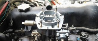
Then the float chamber, like a donor, sends gasoline into two chambers (first and second). Fuel passes through two main fuel jets. The chambers also receive air purified in an air filter, which can be preheated. The picture shows the hole diagram.
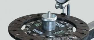
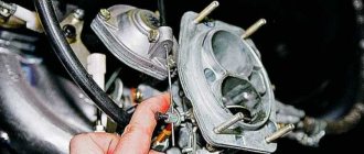
At the same time, air is supplied through air jets, which is mixed with gasoline in special emulsion wells and tubes. As a result, an emulsion is formed, that is, a mixture of air and gasoline. The picture shows a float chamber (with a screwdriver in it) and jets.
Before entering the atomizer, the fuel mixture passes through an eco-stat. At maximum power development, the fuel and air emulsion is further enriched.
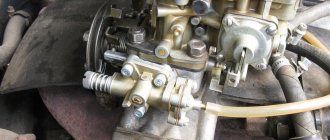
The mixture then passes through special atomizers into diffusers, which prepare the final mixture by “tearing off” droplets of fuel and drawing them into a high-speed air stream, delivering the mixture precisely to the center of the mixing chamber. This is their job. The figure shows diffusers of chambers 1 and 2.
The throttle valve, controlled by the gas pedal, supplies the finished high-quality mixture directly to the cylinders.
There is a system of “idle” jets, in which fuel is taken only from the first chamber. The operation scheme of the cameras provides for the inclusion of the second camera when the unit is well warmed up at full power. The operation of the second camera is fully demonstrated when overtaking at high speed.