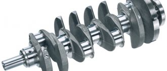
A modern car is a computer on wheels. You know very well how many high-precision sensors modern cars are equipped with - throttle, coolant, oxygen, and so on. However, their role is insignificant in comparison with the importance and functions performed by the crankshaft position sensor - it is one of the few car parts whose failure quite often leads to engine failure.
What is a crankshaft sensor and what is it used for?
In the video, you can check the crankshaft sensor yourself.
Most car enthusiasts know very well what a crankshaft sensor is. If you are not one of them, the following information will be useful to you. As you know, the crankshaft sensor synchronizes the fuel supply process and the operation of the ignition system.
How does this happen? The sensor determines the position of the crankshaft and timing belt, converts the collected information into electromagnetic pulses and transmits it to the engine ECU, which, in turn, directly controls the fuel injection and ignition systems.
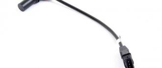
Depending on the car model, the sensor may look different, but the principle of its operation is always the same. Despite the enormous importance of the part, the crankshaft sensor has a fairly simple design - no moving mechanical parts, which accounts for its rather impressive average service life. As a rule, a sensor cannot “fail” on its own initiative; a very common cause of its breakdown is the influence of reagents and salts on the sensor wiring, which results in its corrosion and failure.
In any case, the presence of problems is most easily diagnosed using a special scanner, available in every car service center that respects itself and its customers. If diagnosing the crankshaft position sensor is not included in the list of your additional costs for the car, let’s find out how to do it yourself.
The main “symptoms of illness” of the crankshaft sensor
In the video, information about the crankshaft position sensor
If there are problems with the crankshaft sensor, the most common behavior of the car is failures in engine speed, a significant drop in power, and in some cases, even a complete stop and the inability to start the engine. To avoid such disastrous consequences, it is important to determine the moment when problems arise, even before their obvious manifestation.
Of course, if the most serious repair that you ever carried out on your own was a primitive replacement of the air filter, then the only obvious and sure “symptom” for you will be the “CHECK” light on the dashboard, after which you need to immediately go to a car service center.
If you can handle more serious repairs, then checking the position of the sensor will not cause any special problems. The need for diagnosis will be indicated by:
- a significant decrease in dynamics when driving a car;
- instability and irregular idle speed;
- uncontrolled increase or decrease in engine speed;
- drop in engine power;
- when the speed increases, detonation is observed in the engine cylinders;
- inability to start the engine.
If the above “symptoms” are detected, you should immediately check. Your car may need to replace the sensor immediately.
How to check the crankshaft position sensor yourself - traditional methods
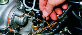
Naturally, before checking the sensor, it needs to be “removed” from under the hood. Despite the fact that it is not located in the most convenient place, this is not a problem for the average driver. However, do not forget that you still have to put it in place, therefore, do not be lazy to note the correct location on the engine body, the location of wires, bolts, and so on. In general, “tie” the sensor in place.
- Visual inspection. The first thing to do after removing the sensor is to inspect for mechanical damage. In addition, you need to check the condition of the contact block and magnetic core. If there are contaminants, they should be removed with alcohol, thinner or gasoline.
- An example check of the crankshaft sensor using a multimeter. This diagnostic method is aimed at measuring the resistance of the sensor winding - the induction coil. If it is damaged, a decrease in resistance indicators will be obvious. Before starting such a test, you should study the instructions for your specific sensor, which will clearly indicate the average normal resistance values. As a rule, this is 500-700 Ohms.
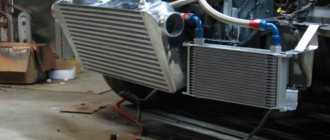
- More accurate check. It is particularly labor intensive. For such diagnostics you will need more serious equipment:
- network transformer;
- megaohmmeter;
- voltmeter;
- inductance meter.
To ensure maximum accuracy of readings, experts recommend carrying out diagnostics at a temperature of about 20 degrees.
The first thing to do is check the winding resistance using the above method. After that, we move on to checking the inductance. Readings in the range of 200–400 mH are considered normal.
The next thing to test is the insulation resistance. Experts say that at a voltage of 500 volts, the insulation resistance should be about 20 megohms. In case of magnetization of the synchronization disk, a network transformer is needed. Since this may cause malfunctions in the operation of the sensor, it should be demagnetized using a transformer.
By analyzing the obtained indicators, you will definitely be able to recognize a malfunction of the crankshaft sensor. After diagnostics, depending on the results obtained, you need to make a decision: either it is enough to carry out maintenance or buy a new part. When installing the sensor at its “working place”, remember that the distance between the magnetized core and the synchronization disk should not exceed 1.5 mm.
Good luck with the renovation!
Signs of sensor problems
The crankshaft speed meter is considered a fairly reliable device, functioning properly for 100 thousand km or more. There are often cases when an element lasts the entire service life of the car. A crankshaft sensor malfunction may occur for the following reasons:
- An internal break or short circuit of the coil winding occurs due to prolonged exposure to vibration transmitted from the engine. Such a breakdown is very rare.
- Open circuit between the device and the controller. The reasons are the same vibration, melting of conductors from contact with hot parts of the engine, or accidental damage by a car enthusiast.
- Mechanical destruction of the body occurs during repairs carried out in the engine compartment. For example, being hit by a broken wrench.
- Loss of contact in the connector due to oxidation or loosening.
- Contamination of the working surface interacting with the toothed pulley.
The last item on the list requires a separate explanation. It is common knowledge that electromagnetic fields penetrate dielectric materials, including dust and dirt. But at the location of the sensor, small metal particles and chips flying from gears are added to traditional contaminants. When they hit the end of the core, they shield the magnetic field, causing the electrical pulse to gradually weaken.
Reference. Contamination of the core with tiny metal particles is typical for worn-out power units with leaking main oil seals. A mixture of engine oil + dirt + chips thickly coats nearby parts, including the crankshaft position meter.
How a car owner can identify the symptoms of a sensor malfunction:
- When the element completely fails, the engine stalls and does not show signs of “life” during subsequent attempts to start, since the controller does not “see” the position of the crankshaft. A broken electrical circuit gives a similar result.
- Unstable operation at idle. The engine speed “jumps” and vibration of the power unit is observed.
- Loss of power from the power unit, failures during acceleration.
- Increased consumption of gasoline or diesel fuel.
As strange as it may sound, the first sign is the most favorable. It is much easier to revive a “dead” motor - just check the circuit or change the sensor itself. In case of unreliable contact and other minor troubles, the engine does not fail, but behaves unstable. The problem is that if other sensors fail and the ignition system malfunctions, the power unit behaves in the same way and identifying the real malfunction is much more difficult.
When the air flow sensor, throttle position sensor or lambda probe is faulty, the control unit switches to emergency mode, supplying fuel according to average indicators. This results in unstable operation and increased consumption. The same symptoms are observed when there is a problem in the crankshaft speed meter circuit.
We carry out verification
I will talk about three options for checking the crankshaft position sensor. To carry out diagnostics, certain devices are used in each method. The simplest option is to check with an ohmmeter. The second option uses several instruments, including a megohmmeter. At service stations, the serviceability of the crankshaft sensor is checked using an oscilloscope. In order to check the sensor, it is necessary to dismantle it. But before dismantling, you should mark its original position with marks so that it can be installed correctly later. Having removed it, you first need to do a visual inspection.
There should be no damage to its body, contacts, core, or contact block. During inspection, all parts must be cleaned of any contamination, especially contacts. You can clean the device with a cloth moistened with gasoline or alcohol. When removing the crankshaft, be sure to check the distance between the core and the synchronization disk, which should be 0.6–1.5 mm. It is adjusted using washers. If no mechanical damage is detected, you can begin checking the electrical circuit of the crankshaft position sensor.
Using an ohmmeter
The easiest way is to use an ohmmeter. Use a multimeter to check the resistance of the coil. The resistance of the sensor depends on the health of the coil. To check, the required range is set and the resistance at the terminals is checked using probes. When working properly, the resistance should be 550-750 Ohms. To be sure that the readings are correct, you need to carefully study the car’s passport. In it you can find the exact values of the parameters that you need to focus on. If the obtained indicators do not meet the standards, then the crankshaft sensor must be changed. This is the simplest method by which you can check the crankshaft. But it does not guarantee 100% correct diagnosis. Therefore, I advise you to conduct a more global check.
Using a megohmmeter
Next, I will tell you how to check the crankshaft sensor in more detail. To do this you will need the following devices:
- megohmmeter;
- digital voltmeter;
- inductance meter;
- network transformer.
For the measurement readings to be accurate, the ambient air temperature must be in the range of 20 - 22 degrees.
Winding resistance is measured, as in the first method, using an ohmmeter. The winding inductance is measured using a special tester. Inductance readings should be in the range from 200 to 400 MHz. During repairs, the sync disk may become magnetized. It is demagnetized using a network transformer. The insulation resistance can be checked with a megohmmeter. At a voltage of 500 V, this figure should not be more than 20 MOhm. After analyzing the obtained indicators, we can draw conclusions about the performance of the crankshaft. If the indicators do not meet the requirements, then it must be replaced with a new one.
Using an oscilloscope
This method of checking is the most accurate and is performed at service stations. To carry out diagnostics, you must have an oscilloscope and special software. The advantage of this method is that you do not need to remove the sensor to carry out diagnostics. Using an oscilloscope, you can monitor how the signal is formed, which determines the presence of problems. When checking with an oscilloscope, the black clamp, which is called the “crocodile”, must be connected to the ground of the engine being diagnosed. The probe probe is installed parallel to the signal output. The second wire is connected to the analog input.
After performing the appropriate actions, signal voltage oscillograms will appear on the device screen. After selecting the mode in which the oscillograms will be displayed, the car engine starts. If the engine does not start, it can be started with the starter.
The nature of the received waves can indicate the presence of faults. The crankshaft sensor, timing disc, or broken teeth may be faulty. After checking the crankshaft sensor, it must either be returned to its place, or, if it is faulty, replaced with a new one. It is installed according to the marks applied earlier. In this case, we must remember the gap between the core and the synchronization disk, which should be in the range from 0.6 to 1.5 mm. You have the right to choose any verification method.
This largely depends on your knowledge and capabilities. The most suitable option, in my opinion, is the second one. True, it requires several devices, but at home it still gives more accurate results. In any case, it is important to take a responsible approach to diagnosis.
Signal diagnostics with an oscilloscope
To obtain correct oscilloscope readings, you need to connect the black clamp to the engine ground, and place the probe probe parallel to the signal output of the sensor. The second connector of the probe must be connected to analog input No. 5 of USB Autoscope II. This procedure is performed in order to obtain voltage oscillograms at the sensor input.
The next stage of diagnostics will be to select the “Inductive_Crankshaft” mode in the program. We start the car.
If the signal from the sensor is present, but its output readings do not coincide with the norms, a slight twitching of the car and difficulty starting the engine may be noticed.
Such irregularities in the output signal indicate existing malfunctions either in the sensor itself or in the sync disk. The exact result can be diagnosed after considering the nature of the voltage clock wave, which is recorded by an oscilloscope at the output of the crankshaft position sensor.
So, 3 ways to check the performance of the crankshaft sensor:
- diagnostics with a multimeter (this is the winding resistance);
- testing with a tester (based on data on inductance and insulation resistance);
- checking on an oscilloscope.
Main symptoms of DPKV malfunction
A faulty sensor or problems with the device’s sensor can be identified by the following symptoms:
- The car's power unit began to detonate. When the engine is running at idle speed or when the speed increases, a knocking sound from the hydraulic compensators appears. The so-called fingers can knock when driving uphill at low engine speeds.
- The car's engine began to function less steadily than before. The speed of the power unit may drop sharply when idling or change upward. The vehicle may stall when idling while standing in a traffic jam or at a traffic light.
- The power unit does not gain the required number of revolutions, although it operates at maximum power.
- The machine's engine power may drop and then increase. In this case, the driver will not take any action.
- The aerodynamic properties and characteristics of the vehicle drop noticeably.
- There are problems starting the power unit. The engine may not start or may start and stall quickly.
- When ignition is performed, the spark disappears. It may not appear at all or occur with a certain frequency.
If the car owner has detected at least three “symptoms” of a DPKV malfunction, the device must be replaced.
It should be taken into account that the described problems do not always indicate a controller failure. They may also indicate other malfunctions in the operation of the power unit. For example, a sharp change in the power of the internal combustion engine and a drop in revolutions indicates a clogged fuel pump or lines connected to it. Signs of a malfunction in the operation of the DPKV may occur when the sensor connection connector is dirty.
The Govorun4eg Auto channel in practice showed signs of problems in the operation of the DPKV.
Trouble-shooting
It makes sense to repair the sensor in case of such malfunctions as:
- penetration of contamination into the PCV sensor;
- presence of water in the sensor connector;
- breakage of the shielding sheath of the sensor wires or harness;
- changing the polarity of signal wires;
- lack of connection to the wiring harness;
- short circuit to ground of the sensor signal wires;
- reduced or increased mounting gap of the sensor and synchronization disk.
Table: working with minor defects
| Defect | Remedy |
| Penetration of PCV sensor and contaminants |
|
| Presence of water in the sensor connector |
|
| Broken shielding of sensor wires or harness |
|
| Changing the polarity of signal wires |
|
| Sensor not connected to wiring harness |
|
| Short circuit to ground in sensor signal wires |
|
| Reduced or increased mounting gap of the sensor and synchronization disk |
|
How to change the crankshaft position sensor?
Important nuances that must be observed when replacing DPKV:
- Before performing dismantling work, it is necessary to apply marks indicating the position of the bolt in relation to the sensor, the DPKV itself, as well as the marking of electrical cables and contacts.
- When dismantling and installing a new PCV sensor, it is recommended to make sure that the synchro disk is operating correctly.
- Replace the measuring device along with the harness and firmware.
To change the PCV sensor you will need:
- new measuring device;
- autotester;
- calipers;
- 10mm wrench.
Algorithm of actions
To change the crankshaft position sensor with your own hands you need to:
- Turn off the ignition.
- De-energize the electronic device by disconnecting the terminal block from the controller.
- Using a wrench, unscrew the screw securing the sensor and remove the faulty DPKV.
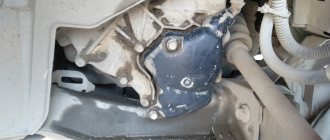
- Clean the planting area from oily deposits and dirt with a rag.
- Install the new meter using the old fasteners.
- Carry out control measurements of the gap between the teeth of the generator drive pulley and the sensor core using a caliper. The gap size should correspond to the following values: 1.0 + 0.41 millimeters. If during a control measurement the gap value is less (greater) than the specified value, it is necessary to adjust the position of the sensor.
- Check the resistance of the crankshaft position sensor with an autotester. For a working sensor it should be in the range of 550–750 Ohms.
- Reset the on-board computer to turn off the Check engine signal.
- Connect the crankshaft position sensor to the network (a connector is installed for this).
- Check the functionality of the electrical appliance in different modes: at idle and under dynamic load.
Photo gallery
Unscrewing the bolt with a wrench Taking measurements with a caliper Installing a new DPKV
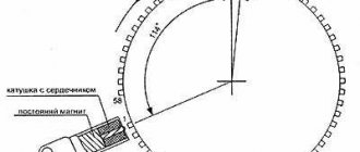
How does the sensor work?
To learn how to troubleshoot the specified device, you need to understand its design and understand the principle of operation. The sensor design is simple and includes the following elements:
- multi-turn coil;
- magnetic core;
- the coil leads are soldered to the connector contacts;
- non-separable plastic case with a hole for fastening.
The meter is installed in close proximity to the toothed pulley attached to the crankshaft on the timing gear side. Through conductors, the sensor is connected to the main electronic unit that controls the operation of the motor.
The magnetic core is brought out through the end part of the plastic case and is as close as possible to the teeth of the rotating pulley. The gap between the parts does not exceed 1 mm.
The operating principle of the device is based on the phenomenon of electromagnetic induction . When a significant mass of metal passes in close proximity to the core, the coil generates a short-term electrical impulse. The teeth of the rotating pulley cause a series of such impulses, transmitted through the wires to the controller. Thanks to this, the electronic unit always “knows” the position of the crankshaft, determines the top dead centers of all pistons and promptly sends a command to the injectors to inject fuel.
This is where the second name of the device came from – crankshaft speed sensor. It must be understood that impulses are generated only under the dynamic influence of the metal mass, that is, when the pulley rotates. If the crankshaft has stopped, no current occurs in the element circuit.
Note. Based on sensor signals, the controller not only promptly directs the fuel mixture to the cylinders, but also commands the ignition system to produce a spark when one of the pistons performs the compression stroke and approaches its top point.
Principle of operation
Let's figure out what the crankshaft sensor is responsible for, because this auxiliary device can be classified as a unique sensor, without which the vehicle engine will not start. Some sources call it a “synchronization mechanism.” Its operation provides the electronic control unit with the ability to operate synchronously with the gas distribution system of the car. Thanks to the device, it is possible to send signals from the ignition system and various types of injection control, which include:
- clock;
- angular;
- cyclical.
When the teeth located on the crankshaft pulley pass through, alternating voltage pulses are generated near the sensor core. This fact affects the operation of the injectors.
The electrical device will not send faults or defective signals. It actually has two types of states: working and non-working. If a failure occurs, it will be an irreversible process. What the crankshaft sensor affects relates to the fuel supply system, so if it breaks down, the device must be replaced immediately.
How to check DPKV for performance?
Checking the operation of the DPKV can be done in three ways:
- multimeter or other similar tester;
- through due diligence;
- using an oscilloscope.
Diagnostics of the crankshaft position sensor with an ohmmeter
Using an ohmmeter, you can ring the controller winding to measure the resistance value. If an ohmmeter is not available, multimeters can be used. As a result of diagnostics, the resistance parameter on the working sensor should be from 550 to 750 Ohms.
The ringing process itself consists of measuring the resistance value of the coil in the inductive controller. If this element of the device is inoperative, the malfunction will affect the operating parameter of the resistance. Therefore, before performing the test, it is necessary to set the required range and diagnose the correct functioning of the device using probes.
The method of checking the crankshaft sensor using an ohmmeter is considered the simplest to implement, but it cannot give a 100 percent result.
Nikolay Vaganov demonstrated the procedure for diagnosing DPCV using a multimeter.
Comprehensive diagnostics of the crankshaft position sensor
If signs of malfunction are detected in the operation of the crankshaft sensor, you can resort to a comprehensive check method. This diagnostic option is difficult to implement, but more accurate. To carry it out, you will need a set of instruments and equipment that is not available at every service station.
To complete the task you will need:
- megohmmeter;
- network transformer device will be used to decrypt information;
- a traditional sample device for measuring inductance;
- multimeter or digital voltmeter.
When performing a comprehensive diagnosis of the crankshaft sensor, it is recommended to maintain the temperature in the region of 20-22 degrees. This condition is required to ensure correct values that the equipment will produce.
Features of complex device diagnostics:
- Using an ohmmeter or other tester, the working resistance value is diagnosed.
- Using an inductance measuring device, the amount of induction on the controller winding is measured. If the sensor is operational, then the resulting value should be in the region of 250-400 mH.
- Then the procedure for measuring the resistance value on the insulating layer is performed. When a voltage of 500 volts is applied, the operating parameter value should be about 20 mOhm. A network transformer device will be required if periodic magnetization of the controller occurs. If the device is working properly, then all values obtained as a result of the test will be within the established limits.
The Auto Electrician HF channel showed another unique option for diagnosing the controller - using a wrench.
Diagnostics of the crankshaft position sensor signal using an oscilloscope
This diagnostic option is the most accurate of all those described. This is because not only the spare part for the crankshaft is checked, but also its design during engine operation. The essence of diagnostics is to connect an oscilloscope to the controller and monitor signals through icons that extend from it. When performing the test, there is no need to remove the sensor from the power unit, since all actions will be performed with the internal combustion engine running.
Diagnostic algorithm:
- The cable with the black clip connects to the ground or “ground” of the vehicle’s power unit.
- Then the probe probe is installed to the signal contacts of the controller itself. The connection is made in parallel. To identify a signal output, the corresponding connector must be marked with the symbol A.
- The next step is to connect the second probe of the diagnostic equipment. The connector connects to the analog input of a computer or laptop. The latter must have the software installed and configured in advance.
- When all electrical circuits are connected correctly, a signal from the oscilloscope will appear on the PC screen. It will be presented in the form of a graph. The pulse voltage is determined at the input of the controller being diagnosed.
- To perform diagnostics on the equipment, you must specify a special graph output mode. This mode is called Inductive Crankshaft. After setting all the parameters, the power unit is started. Then all parameters from the controller are monitored.
When receiving an impulse from the controller that does not correspond to the nominal parameters, the power unit will twitch noticeably. There may be difficulties when starting the engine.
The appearance of such defects when monitoring output pulses from the controller will indicate the following problems:
- malfunctions in the controller design;
- malfunctions in the operation of an element designed to work with the synchronizing shaft;
- defects in the teeth.
It will be possible to determine exactly which component is inoperative after a complete diagnosis of the type of change in the pulse waves. Usually it is not the controller itself that needs to be replaced, but the toothed disk - over time it wears out and becomes unusable.
The Car Diagnostics channel talked about the features of checking the DPKV using a pocket oscilloscope.
Diagnosis of DPCV
If the car does not start, it may be due to a faulty DPKV. Then the device must be removed and diagnosed.
Symptoms of a problem
The main symptoms of a malfunctioning crankshaft position sensor are the following:
- Engine detonation occurs periodically, i.e., spontaneous ignition of the fuel.
- The car simply won't start.
- The dynamics of the car and engine power are significantly reduced.
- When switching modes, a spontaneous change in the number of revolutions, etc. is observed.
This is interesting: The key role of sandblasting equipment in car painting
Thus, you do not need to be a professional to determine whether the sensor is faulty. It is enough to pay attention to the dynamics, quality of the car engine and other obvious signs.
Using an Ohmmeter
So, you have removed the DPKV and externally determined the presence of malfunctions. But only special devices will help to identify hidden threats and internal disruptions in work. This also includes an ohmmeter.
An ohmmeter determines the current resistance in a circuit. Based on the indicators of the device, you can judge whether the sensor is serviceable or broken. The optimal resistance values for such devices are 550 - 750 Ohms.
Using an Oscilloscope
The next device is an oscilloscope. It is recommended to use it with the engine running without removing the sensor. But if this is not possible, the device can be removed from the engine and diagnostics can be carried out offline.
Using an oscilloscope, you can not only obtain the final values, but also thoroughly study the process of their formation and transmission to the central unit. Thus, diagnostic results using such a device provide the most comprehensive results.
The oscilloscope diagnostic process consists of several simple steps:
- Connect the measuring device to the sensor. Polarity may not be observed.
- Run a program on your PC that can be used to track the device’s values.
- Pass a metal object in front of the sensor several times.
- Observe the signals on the PC screen. If the oscillogram shows the movement of a metal object, the sensor is working. Otherwise, you need to carry out a comprehensive diagnosis.
Comprehensive examination
The methods described above provide only one-sided information about the state of the sensor. To obtain comprehensive information, it is necessary to conduct a comprehensive examination. This includes the use of the following devices:
- Multimeter. It includes ohmmeter, voltmeter and ammeter functions, measuring resistance, voltage and current respectively. Advanced versions of the multimeter may include other functions.
- Megaohmmeter. It differs from a conventional ohmmeter in that the resistance in the circuit is measured at high voltage values, which are artificially created by the device.
- Inductance meter.
Before starting a comprehensive examination, the sensor must be removed from the engine, thoroughly washed and dried. After this, you can start measuring. It is carried out only at room temperature so that the readings are as accurate as possible.
First, measurements are taken with a multimeter. Next, the inductance of the circuit is measured. Lastly, a megohmmeter is used.