Hi all! Not long ago I installed an electric Carlson instead of a forced one. I installed it on standard wires, that is, the circuit was closed stupidly through the sensor and there was no talk of any relays. Moreover, they were smart enough to parallel the button with the sensor. But after a major overhaul of the engine, there was a need to drive for some time with the propeller constantly on. Accordingly, after some time, the negligent connection made itself felt by the smoke of burning wires from behind the tidy.
Having rummaged through the Internet and books, I found, as it seemed to me, a successful connection diagram via a relay and even with a button (www.vaz2101.spb.ru/articl…ventilyatorom_p2_connect/). Everything seemed fine, but in order to assemble it all you needed not only wires and tools, but also a deep understanding of what you were doing, and since I’m not very good at auto electrics, to put it mildly.
That same deep understanding came with the study of hardware, namely the operating principle of a 4-pin relay through which all this obscenity is connected.
To be brief, the principle of its operation is identical to the operation of an electromagnetic starter, i.e. currents in the control circuit (pins 86 and 85) are closed on a coil, which closes a contact in the power circuit (30 and 87)
Thus, using the button, the coil is controlled.
The author's diagram has been slightly corrected. It took 6 meters of wire, a relay, a button in the dashboard (a fan is drawn on it).
Using an electromagnetic relay
Using a simple relay will slightly complicate the circuit, but will relieve the temperature sensor from the presence of high current. A large current will flow through the relay contacts. It is cheaper and easier to replace the relay than the temperature sensor to turn on the electric fan. To carry out the upgrade, you will need a wire and a relay with a bracket for mounting to the body.
Disconnect the temperature sensor, and the wires that were on it must be connected to the normally open pair of contacts of our relay. Half the job is done, the power part is ready. Now control. We connect one terminal of the temperature sensor to ground, but connect the second to the relay coil.
From the second terminal of the coil you need to stretch the wire to the positive terminal of the battery. It is advisable that the connection be made through a fuse, the operating current of which can be 1 Ampere. The coil consumes a small amount of current, so the worst thing that can happen is a short circuit in the wiring. Subsequently, you can connect a forced activation button in parallel with the temperature sensor, which you will install in the car interior.
Installing a forced fan button for VAZ 2114
You should start work by disconnecting the ground terminal from the battery so that a short circuit does not occur during the connection of the electrical circuit. The procedure for installing the button is as follows:
- Prepare a block to which the button for forced activation of the VAZ 2114 fan will be connected. To do this, you need to leave 4 terminals with wires on it: two central ones for illuminating the button and two corner ones for controlling the power circuit of the electromagnetic relay.
- Connect two wires with lugs to the electric fan power wires that go to relay K1 (pins 30 and 87). To do this, you need to strip off some of the insulation on the wires approaching the relay and screw the pieces of wire that will go to the relay to them. Ideally, it is better to solder the connection, but you can get by with just a tight twist. The connection points must be carefully insulated.
- Connect the tips of the connected wires to the relay block to pins 30 and 87.
- Connect the control wire from the button block to terminal 85 of the relay, and connect terminal 86 with a wire to the vehicle ground. Install the fan switch button into a free slot on the dashboard, having first removed the plug.
- Install the relay in a convenient place, for example, under the dashboard of a car, and secure it.
- Connect ground to the battery.
- Turn on the ignition and press the fan button. The relay should click and the fan motor should turn on.
This completes the installation of the forced fan button on the VAZ 2114.
Semiconductor Applications
Instead of an electromagnetic relay, you can use a thyristor switch, or a design based on field-effect transistors. The essence is the same, only there are no moving contacts; their functions are performed by electrons and holes in the semiconductor crystal. But do not forget about cooling the thyristors and transistors, install radiators that will be able to provide the necessary heat transfer.
Soft engine start is a very useful function for engine control. This innovation will ensure a gradual increase in the load on the electric motor. This idea is accomplished by using PWM modulation. But along with all the innovations, you can use a second temperature sensor in the cooling system, whose response temperature is 5 degrees lower than the main one.
How does the fan turn on?
Unlike carburetor engines, in VAZ 2110 injection engines the fan is turned on not directly from the temperature sensor, but through the electronic control unit (ECU). The sensor is installed on the outlet pipe of the cylinder head.
VAZ 2110 injector cooling fan does not turn on: reasons, how to check
When the coolant heats up to a temperature of 100-107 0 C, the sensor is triggered and sends a signal to the ECU, which processes it and sends it to the relay. The relay closes the circuit and supplies power to the fan drive (electric motor) through a fuse.
Fan connection 2108, 2109, 21099
Until 1998, on cars with the old mounting fuse block 17.3722 (finger type fuses), relay 113.3747 was included in the fan circuit. After 1998 there is no such relay.
Also, before 1998, the TM-108 switching sensor was used (the closing temperature of its contacts is 99±3ºС, the opening temperature is 94±3ºС), after 1998 the TM-108-10 with similar temperature ranges or its analogues from different manufacturers. The TM-108 sensor only works in conjunction with a relay; the TM-108-10, reinforced for high current, can work both with and without a relay.
Scheme for switching on the engine cooling fan on a VAZ 2109 with mounting block 17.3722
- Fan motor
- Motor start sensor
- Mounting block
- Ignition switch
K9 - Relay for turning on the fan motor. A - To terminal “30” of the generator
Scheme for switching on the engine cooling fan on a VAZ 2109 with mounting block 2114-3722010-60
- Fan motor
- Sensor 66.3710 for turning on the electric motor
- Mounting block
A - To terminal “30” of the generator
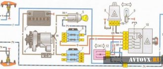
Radiator fan diagram, relay connection
The design and circuit diagram of the radiator fan may differ not only depending on the make of the car, but also on the year of manufacture and model configuration. Let's consider not only the principle of operation, but also the connection option with the possibility of forced activation of the cooling system fan (VSO).
Cooling system design features
Depending on the design features, the fan can be turned on in 3 ways:
- using a power sensor for activation of the VSO. This sensor is also called a fan temperature relay, since the power contacts of the electric motor pass directly through the sensor. With this scheme, the load on the thermal relay increases significantly, which reduces its service life;
- using the fan switch sensor, but now closing the contacts in the temperature switch triggers the relay, through which the power contacts of the cooling fan are connected. This connection method is much more reliable than the previous option;
- using an electronic engine control unit. The ECU, focusing on the coolant temperature sensor installed in the engine cooling radiator, supplies power to the VCO through a relay. A resistive temperature sensor is used as a meter. It is this switching circuit that is used on the vast majority of modern cars. On cars equipped with air conditioning, one of the electric fans will be controlled by the comfort unit. This is necessary for forced cooling of the condenser when the interior air conditioning system is activated.
Operating modes
When understanding the operating principle and connection diagram of a radiator fan, you should remember that electric motors often have two speed modes. This is implemented in 2 ways:
- by adding a resistor to the circuit, which increases the resistance and, as a result, reduces the current. The design uses a two-contact sensor, which, depending on the temperature, powers the electric motor directly or through resistors;
- a combination of parallel and series connection. The circuit is used on a car with two fans. They can be connected in series, in which case, according to Ohm's law, they will operate from 6 V, or in series, when 12 V is supplied to each of the VSOs. The modes correspond to low and high speed rotation of the propeller.
Scheme options
Schematic diagram of VSO connection on VAZ 2108, 2109, 21099 (until 1998).
As we can see, the sensor controls the fan relay, which is located in the fuse box. When a certain temperature is reached, the contacts of the temperature switch close, which leads to the flow of current in the electric motor circuit.
Above is a diagram for VAZ 2108, 2109, 21099 cars, but after 1998. As we can see, the power sensor now functions as a relay.
Let's consider a circuit using a resistor to implement two propeller rotation speeds using the VW Passat as an example. The two-position fan power sensor S23, depending on the coolant temperature, closes the contacts directly or through an additional resistance.
DIY connection
Some drivers, warning the engine against overheating due to improper operation of the radiator fan power supply thermal relay, make an external button to force the electric motor to turn on. To do this, it is enough to connect a fixed button in parallel to the control output of the relay coming from the sensor, which, when pressed, will close the contact to ground, thereby provoking the operation of the relay. If the car's design does not provide a fan relay, you will have to install it yourself to force cool the radiator.
Under no circumstances should you connect the electric motor directly through the button in the cabin! We also do not recommend connecting the circuit so that after turning on the ignition the electric fan constantly rotates, as this significantly reduces its service life.
To connect, you only need to understand the operating principle of a 4-pin relay and minimal knowledge in installing additional equipment. Be sure to include a fuse of the correct rating in the power circuit and place it as close to the power source as possible (read more about how to choose the correct fuse rating).
If desired, you can replace the single-position sensor with a two-position one, which, paired with a selected resistor, will allow you to realize a low speed of operation of the VSO. If you have a sufficient level of knowledge in electrical engineering, then you can build a PWM controller to adjust the speed of rotation of the propeller. Controlling the electric fan using a PWM signal will allow you to smoothly regulate and arbitrarily select the rotation speed depending on the temperature load on the engine. There is enough material on the Internet on how to make a PWM controller with your own hands.
autolirika.ru
Connection diagram for VO VAZ 2110
The circuit diagram for switching on the cooling fan of the VAZ 2110 on carburetor and injection cars is different. On cars with a carburetor engine, a thermobimetallic sensor TM-108 is used for this, and on cars with an injection engine, control is carried out by a controller.
Connection methods
Installing the future fan is half the battle; the main thing is to connect the power cable to it. If the bathroom has already been renovated well, this will be problematic. The ideal option would be to install the ventilation device at the stage of repair work, then the cable can be laid in the walls. Otherwise, you will have to come up with some kind of decorative design for it or plug it into an outlet.
Let's consider options for connecting a ventilation device:
- Diagram of parallel connection of a fan with a light bulb. In this case, both the fan and the lamp will operate from one switch. That is, the ventilation device will begin to rotate at the same time as the light comes on, and will be in operation as long as the light is on. The undoubted advantage is the simple and cheap implementation of such a scheme. However, there are many disadvantages. If the switch is turned off, it means the fan is not working, and this is not enough to ventilate the room. You will have to turn on and leave the light on for a while. On the other hand, the fan will always work when the light is on, and when a person takes water procedures, he does not need these drafts.
- Circuit from the switch. This method is definitely good, because it eliminates the stupid operation of the hood. That is, the device turns on and off only when needed. You can install a switch separately for the fan, or mount a 2-key switching device and power the lighting from one key, and the ventilation device from the second. This option will increase costs since more cable will be required. After all, the device is already connected directly from the switch with a separate line, and not parallel to the lighting.
- The latest fan models are already equipped with automation, in particular a timer. To connect such a device you will need a three-wire wire or cable; the third wire is connected through the light bulb and is a signal wire. There are two options for operating this fan. It can start simultaneously with the lighting turning on, and then turn off after a set time. Or vice versa, while the light is on, the engine does not start, but as soon as the light goes out, the fan starts working, and then it turns off after a certain period of time.
There are also fan models that are initially equipped with their own switch. It has the shape of a cord that comes out of the body. Pulling this cord starts and turns off the device. But keep in mind that such models are completely inconvenient to maintain. Fans are usually installed near the ceiling, and this place is difficult to reach to reach the cord every time.
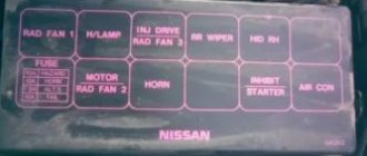
Where is the fan relay located?
4 – electric fan relay; 5 – electric fuel pump relay; 6 – main relay (ignition relay).
Attention: the order of the relays and fuses can be arbitrary, we are guided by the color of the wires. Therefore, we find a relay from which comes a thin pink with a black stripe wire coming from the main relay (pin 85*) (not to be confused with the thin, red with a black stripe wire coming from the controller) and a thick power white with a black stripe wire (pin 87) (white and pink wires we need), this is the fan relay.
Fan installation
A two-core cable must be laid to the installation site of the ventilation device. Connecting a fan model with a timer to a one- or two-key switch is done with a three-wire wire (the third wire will be the signal wire).
Make grooves from the junction box to the ventilation hole. Remember that you can only groove with vertical or horizontal lines, there should be no inclined lines. Do not make grooves closer than 10 cm to the doorways. Place the cable in the groove made and secure it with alabaster or cement mortar. One end of the cable should be led out into the ventilation hole, the other into the junction box.
If the cooling fan does not work
To drive the fan, a DC electric motor with excitation from permanent magnets ME-272 or similar is installed. Technical data of the electric fan and fan switch sensor:
- Rated rotation speed of the electric motor shaft with impeller, 2500 – 2800 rpm.
- Electric motor current consumption, 14 A
- Sensor contact closure temperature, 82±2 degrees.
- Sensor contact opening temperature, 87±2 degrees.
The cooling system fan may not turn on due to:
- electric drive malfunctions;
- blown fuse;
- faulty thermostat;
- a failed thermal sensor for turning on the cooler;
- faulty VO relay;
- broken electrical wiring;
- faulty expansion tank plug.
To check the VAZ fan electric motor itself, we apply 12 V voltage from the battery to its terminals - a working motor will work. If the problem is with the fan, you can try to repair it. The problem is usually the brushes or bearings. But it happens that the electric motor fails due to a short circuit or break in the windings. In such cases, it is better to replace the entire drive.
The BO fuse is located in the mounting block of the car's engine compartment and is designated F7 (20 A). The test is carried out using a car tester turned on in probe mode.
- In a car with a carburetor engine, you need to check the sensor - turn on the ignition and short-circuit the two wires going to the sensor. The fan should turn on. If this does not happen, the problem is definitely not with the sensor.
- For injection cars, it is necessary to warm up the engine to operating temperature and disconnect the sensor connector, disconnecting it from the vehicle’s on-board network. In this case, the controller must start the fan in emergency mode. The electronic unit perceives this as a failure in the cooling system and forces the fan drive to operate in constant mode. If the drive starts, the sensor is faulty.
Diagram - relay for turning on the fan of the car cooling system
There are many schemes for implementing the cooling system operation circuit; let’s consider one of them, which has proven to be the most effective. The principle of operation is to turn on a fan that cools the engine when it reaches a certain temperature.
As a result, the device will be a relay with a control system for a switching relay when a certain engine temperature is reached. The circuit diagram is based on switch 130 from the ignition system of a GAZ car; switch 131 from later models cannot be used; this diagram is not valid for it. The 130th switch can be bought at any auto store; it’s not in short supply, so you can easily get it.
The weakest point in this switch is the KT848 transistor; the power transistor is located on the radiator. If the element breaks down, the problem is most likely in this transistor.
So, based on this switch we build the circuit shown in the following figure.
The principle of operation is simple: as the temperature increases, the voltage level on the sensor decreases. It is clear that almost all the voltage falls on the trimming resistor R**, at the moment when the voltage on the trimming resistor becomes less than the stabilization voltage of the zener diode V**, the transistor will close, which in turn will lead to the opening of transistors V5 and V6.
Thus, power will be supplied to the control contacts of the PC503 relay (see third figure), it will switch and the fan will begin to rotate. Resistor R3 plays an important role in the circuit; its value determines the value of the engine temperature at which the fan will turn off.
The lower the value of resistor R3, the greater the temperature difference between turning the fan on and off. In other words, if the value of resistor R3 is reduced, the engine will have to cool longer.
To avoid failure of the relay, resistor R3 should not be set to less than 50 kOhm; in general, its value varies in the range from 50 kOhm to 1 Mohm. Resistor R** is a more subtle tool for adjusting the relay switching temperature; with it, you can adjust the switching temperature with an error of 1 degree. The general connection diagram of the circuit diagram, relay, power, temperature sensor is presented below.
The device will be located in an aggressive environment subject to vibration and temperature, so the initial setting to a certain temperature will change by 2-3 degrees over time. Otherwise the scheme performed very well.
Similar articles:
xn—-7sbgjfsnhxbk7a.xn--p1ai
Replacing an electric fan in a car
- We park the car on a flat surface and immobilize it with the parking brake.
- Open the hood and disconnect the negative terminal.
- Using a 10mm wrench, unscrew the fastenings of the air filter housing.
- Using a screwdriver, loosen the air duct clamp on the air flow sensor and remove the corrugation.
- We unscrew the screws securing the cover of the air filter housing and remove the filter element.
- Using a size 8 wrench, unscrew the air intake mount and remove it.
- Using a 10mm wrench, then an 8mm wrench, unscrew the nuts securing the fan casing around the perimeter (6 pieces in total).
- Disconnect the wire block on the fan connector.
- Carefully remove the fan casing along with the drive.
- Using a 10mm wrench, unscrew the 3 bolts holding the electric motor to the casing.
- We put a new one in its place.
- We install the structure in place, fix it, and connect the connector.
- We carry out further installation in the reverse order.
Diagnostics and repair
It is recommended to check the fan and elements of its electrical circuit in the following order:
- Fuse.
- Relay.
- Electric motor.
- Temperature sensor.
Checking the functionality of the fuse
The fuse is usually checked first, as this process is the simplest and does not take much time. To carry it out, you only need an autotester or a test lamp. The essence of the diagnosis is to determine whether it passes electric current.
The fan circuit fuse is installed in the vehicle's mounting block, which is located in the engine compartment. In the diagram it is designated as F-7 with a rating of 16 A. To check and replace it, you must perform the following work:
Relay diagnostics
As we have already said, in the injection “sevens” a relay is provided to unload the electrical circuit of the radiator fan. It is installed in an additional mounting block located under the glove box in the car interior, and is designated R-3.
Checking the relay yourself is quite problematic. It is much easier to take a new device and install it in place of the one being diagnosed. If the electric fan turns on when the refrigerant is heated to the desired temperature, then that was the problem.
Checking and replacing the electric motor
Required tools:
- voltmeter or multifunction autotester;
- two pieces of wire;
- socket wrenches “8”, “10” and “13”;
- pliers.
The work order is as follows:
- Disconnect the fan power connector.
- To the contacts of the half of the connector that comes from the electric motor, we connect two wires, the length of which should be enough to connect them to the battery terminals.
- We connect the ends of the wires to the battery terminals. If the fan does not turn on, you can prepare to replace it.
- If it works properly, it is worth checking whether voltage is supplied to it.
- We connect the voltmeter probes to the contacts of the other half of the connector (to which voltage is supplied).
- We start the engine, use a screwdriver to close the sensor contacts (for carburetor cars) and look at the device readings. The voltage at the contacts should be equal to what the generator produces (11.7–14.5 V). For injection machines, there is no need to short-circuit anything. It is necessary to wait until the engine temperature reaches the value at which the electronic control unit sends a signal to the relay (85–95 OS), and read the instrument readings. If there is no voltage or it does not correspond to the set values (for both types of engines), the cause should be sought in the device circuit.
- If a malfunction of the electric motor is detected, use an “8” socket wrench to unscrew the 2 bolts securing the fan casing to the radiator (left and right).
- Carefully pull the casing towards you, while simultaneously releasing the sensor wires from the retainer.
- Using pliers, we compress the tabs that secure the wire sheath. We push the clamps out of the casing.
- We dismantle the fan assembly.
- Holding the impeller blades with your hand, unscrew the nut securing it using a socket wrench set to “13”.
- Disconnect the impeller from the shaft.
- Using a “10” wrench, unscrew all three nuts that secure the electric motor housing to the frame.
- We remove the faulty electric motor.
- We install a new device in its place. We reassemble in reverse order.
Diagnostics and replacement of temperature sensor
Temperature sensors for carburetor and injection "sevens" differ not only in design, but also in their operating principle. For the former, the sensor simply closes and opens the contacts, while for the latter, it changes the value of its electrical resistance. Let's consider both options.
Carburetor engine
Tools and tools you will need:
- open-end wrench at “30”;
- socket wrench or socket to “13”;
- ohmmeter or autotester;
- liquid thermometer with a measuring range of up to 100 °C;
- a clean container for collecting refrigerant;
- container with water;
- gas (electric) stove or household boiler;
- dry clean rag.
The check and replacement algorithm is as follows:
- We place the container under the plug on the cylinder block of the power plant.
- Unscrew the plug and drain the refrigerant.
- Disconnect the connector from the sensor contacts.
- Using a key set to “30”, unscrew the sensor.
- We connect the ohmmeter probes to the sensor contacts. The resistance between them in a working device should tend to infinity. This means that the contacts are open.
- Place the sensor with its threaded part in a container of water. We do not turn off the probes of the device. Heat the water in the container using a stove or boiler.
- We observe the thermometer readings. When the water reaches a temperature of 85–95 °C, the sensor contacts should close and the ohmmeter should show zero resistance. If this does not happen, we change the sensor by screwing a new device in place of the old one.
Video: how to prevent engine overheating with a faulty sensor
Injection engine
The injection “seven” has two temperature sensors. One of them works in tandem with a device that shows the coolant temperature to the driver, the other with the ECU. We need exactly the second sensor. As already mentioned, it is installed on the pipe next to the thermostat. To check and replace it we will need:
- autotester or multimeter with the ability to measure voltage and resistance;
- open-end or ring wrench set to “19”;
- liquid thermometer with temperature measurement amplitude up to 100 °C;
- heat-resistant container with water;
- boiler or stove (for heating a container of water);
- clean dry cloth.
The order of work is as follows:
- We find the sensor. Disconnect the connector from its contacts.
- Turn on the ignition.
- Turn on the multimeter or tester in voltage measurement mode. We connect the probes of the device to the connector contacts. Let's look at the readings. The device should show approximately 12 V (battery voltage). If there is no voltage, the problem must be looked for in the device’s power circuit.
- If the device shows the standard voltage, turn off the ignition and remove the terminal from the battery.
- Using the key set to “19”, unscrew the sensor. In this case, a small amount of coolant may leak out. Wipe off any spills with a dry cloth.
- We switch our device to resistance measurement mode. We connect its probes to the sensor contacts.
- We place the sensor with the working part in a container with water.
- We heat the water, observing the change in temperature and resistance. If the readings of both devices do not correspond to those given below, we replace the sensor.
Table: dependence of the resistance value of DTOZH VAZ 2107 on temperature
Control circuit modernization
The cooling fan on the top ten turns on at a temperature of 100-105°C, while the normal operating temperature of the engine is 85-90°C, so the fan turns on when the engine overheats, which naturally has a negative effect.
This problem can be solved in two ways: adjust the switch-on temperature in the “brains” or make a button. We'll focus on the second one. Turning on the fan from the button is very convenient: if you get into a traffic jam, turn it on, drive out, turn it off, and no overheating occurs.
A button for selecting the fan operating mode was installed in the cabin (always off, constantly on, automatically turned on via a sensor) - this “tuning” is not mandatory, but will be a very useful addition.
There will be a large current at relay contacts 87, 30, on the wire from the battery to the fuse and the fan ground, and therefore we must use wires there with a cross-section of at least 2 mm, otherwise the thinner wire will not withstand it and will burn out.
How to turn on the cooling fan on a VAZ
Author KakSimply!
An electric fan can be turned on in two ways. The first is using an electromagnetic relay, and the second is without it. But in any of these schemes it will be useful to use a button to force the fan on.
Instructions
Cars use electric fans to blow air over the radiator of the cooling system. The fan is an impeller driven by a DC electric motor mounted in a round or square frame. The activation of the electric fan is fully automatic and depends on the temperature of the coolant in the radiator. Fluid temperature data is taken from a sensor installed in the side compartment of the radiator. The sensor is a simple microswitch whose contacts are normally open. They close when a certain temperature is reached. To connect an electric fan, you can use two circuits: relay and relayless. The difference between these schemes is clear from the name. The relayless circuit consists of a temperature sensor, fan, fuse, and connecting wires. The positive terminal of the electric fan is connected through a fuse to the positive terminal of the battery. The negative terminal of the fan is connected to any terminal of the temperature sensor; the polarity of the connection does not matter. The second terminal of the sensor must be connected to the car body. This is the simplest switching scheme and does not require much time to implement.
The relay circuit contains an electromechanical relay. The good thing is that the high current is removed from the sensor to the relay. The positive terminal of the fan is connected through a fuse to the battery, the negative terminal to the body. The negative wire must be cut and the resulting two wires connected to the normally open contacts of the relay. By default, our fan is turned off. One terminal of the relay coil must be powered from the battery positive through a fuse, or from the ignition switch. The second output of the coil should be applied to the first contact of the temperature sensor, and a wire connected to the body should be mounted from the second contact. Check in advance to see if the relay has a diode connected in parallel with the coil. If available, it is important to observe the polarity of the winding power supply.
Another useful modification for the fan switching circuit is a button installed in the car interior. The temperature sensor can fail at the most inopportune moment, so the button will be useful in emergency situations. Both when using the first scheme and when using the second, you need to connect the normally open contacts of the button to the temperature sensor. It’s easier this way, but if you use the first scheme, it turns out that there will be a large current on the button, and this can cause the button contacts to burn and the case to melt. Therefore, it is best to use the button in combination with an electromagnetic relay.
There are two ways to connect power supplies: series and parallel. With the first, the total voltage increases, and with the second, the capacitance increases. The increase occurs a number of times equal to the number of sources.
Instructions
Make sure both batteries are the same, equally worn, and charged to the same degree. If this is not the case, avoid connecting them in series or parallel. To connect two batteries in series, connect the negative terminal of the first battery to the positive terminal of the second. Do not connect the terminals that remain free (the positive pole of the first and the negative pole of the second) to each other under any circumstances, otherwise a short circuit will occur. Remove the tension from them, which has doubled. To connect two batteries in parallel, take two diodes that can withstand the load current for an unlimited period. Connect the negative poles of the batteries together. Connect the positive pole of one of the batteries to the anode of the first diode, the other - to the anode of the second diode. Connect the cathodes of the diodes together. Connect the load with the negative pole to the connection point of the negatives of the batteries, and the positive pole to the connection point of the cathodes of the diodes. This design will deliver the same current twice as long as a single battery. But you cannot load it with twice the current, since only one of the diodes is always open. It is not recommended to connect batteries in parallel without diodes, since they will discharge through each other. Do this only if you are absolutely sure that they are equally charged and worn out. But with such a design you can extract twice as much current. Before charging batteries, disassemble the structure. Charge them separately. This will significantly slow down battery wear. If the batteries are connected in parallel using diodes, it will be completely impossible to charge them without disassembling the structure. After charging is complete, reassemble the structure and connect the load to it. Continue using the batteries.
Sources:
Troubles in the cooling system are the most dangerous. Without monitoring the fluid temperature, you can leave the engine without cooling. The result is a major overhaul, since the engine will simply jam. Therefore, you need to detect the malfunction in time and try to eliminate it.
The cooling system on both the VAZ 2107 and the VAZ 2109 has the same design. The only significant difference is the type, since the nines use a sealed system. The expansion tank has a plug with two valves. The inlet is triggered when the pressure drops to 0.13 atmospheres, and the exhaust is triggered when it reaches 1.2-1.3 atmospheres. On early VAZ models, the coolant is not under such high pressure. Due to the increase in pressure in the cooling system, antifreeze (or antifreeze) has a higher boiling point. The most common breakdown in all cars is the thermostat. A sign of thermostat failure is boiling of the coolant even when driving at high speed, when there seems to be good airflow to the radiator. The reason lies in the fact that a thermostat is necessary to switch the liquid circulation between large and small cooling circles. When VAZ thermostats fail, they leave a small circle on. And this is the entire system, except for the main radiator. Hence the excessive heating.
The second most popular failure is the failure of the pump (liquid pump). There is practically nothing to break in it, but often the oil seal through which the coolant leaks out is destroyed. Sometimes the bearing wears out and it begins to make a terrible whistling and grinding noise. These are the main malfunctions of the pump; they can be determined by hearing and sight. True, sometimes the bearing is destroyed so that it does not make sounds, but axial play appears.
The electric fan is the third most popular component in which a breakdown may occur. Sometimes it stops working due to the failure of the temperature sensor responsible for turning it on. But often the cause of the malfunction is electrical wiring. On nines, for example, a simple fan circuit is used. Fuse, sensor and fan itself. The sensor is connected to ground and to the fan. So the wire that goes to the body is quite long and runs throughout the entire engine compartment. The slightest break and the fan fails.
If the thermostat has died for a long time on a long journey, then first try knocking on its body. Sometimes, after exposure, the valve opens, but expect it to jam again soon. The best option is to drain the fluid and try to break through the thermostat to turn on the big circle. And if suddenly there is a new one or a working one in the glove compartment, then install it. It’s more difficult with a pump on the road; it will be easier to add water as needed. But this is only if the leak is not very large. Having reached the place where repairs can be carried out, it needs to be replaced. On sevens this is done quite quickly, you just need to drain the liquid, loosen the fan belt and remove the old pump. And on nines you will have to remove the casing that covers the timing block, loosen the belt, and only then use a 10mm wrench to unscrew the three bolts securing the pump.
But with a fan everything is simpler. If there is a breakdown in the sensor, then the easiest option is to short-circuit its contacts. In this case, the fan will work constantly, so after stopping the engine, be sure to turn it off, as the battery will run out. If the problem is in the wiring, then the best way to get out of this situation is to connect a fan to the battery. But if the electric motor winding burns out, then only a complete replacement will help.
Sources:
- Description of the VAZ 2107 cooling system
- Typical failures in the cooling system in 2017
The engine cooling system is one of the important parts of the car. It not only cools the engine, but also heats the car interior in winter. And to carry out maintenance and repair, you simply need to know the composition of the system and the general principle of its operation.
The first copies of VAZ 2110 cars were practically a copy of the nines. The only difference is in the body, but the engine and gearbox are similar. But carburetors were replaced by an injection system, and a lot has changed in the car, including the cooling system. Constant modernization makes itself felt, the car becomes more reliable, but more difficult to maintain. Of course, increasing engine power entails a lot of modifications. Changes occur in the braking system, lubrication and cooling systems. But the principle of operation remains virtually unchanged. It is very difficult to single out the most important element, since all components play the main role in the cooling system. Let's start with the first thing that catches your eye. This is an expansion tank with a plug in which there are two valves (inlet and outlet). While the engine is running, the coolant heats up and expands. The tank is necessary to release excess fluid from the system. The radiator, fan and temperature sensor are parts located at the front of the car. A radiator is necessary for effective cooling of the liquid in the system. The fan is triggered by a sensor and blows a strong air stream onto the radiator. Due to the blowing, significant heat is removed from the radiator. The sensor is a simple switch whose contacts close at a certain temperature. A pump installed in the engine block, driven by the timing belt, is necessary to ensure the circulation of coolant in the system. And the thermostat simply switches the cooling circuits. There is also a radiator in the heating system; it is installed in the stove (snail). One pipe from the block (hot liquid) goes to it through a faucet installed on the body. And one pipe comes out from the stove and goes to the thermostat. The pipes and clamps are minor parts, but they affect the operation of the entire system, since it is through them that the coolant moves. The slightest crack in the pipe can cause a rapid decrease in the coolant level and an increase in its temperature. There are one or two temperature sensors in the engine block; they are necessary for the operation of the temperature gauge and the ECU. When starting a cold engine, the coolant moves in a small circle. To put it simply, all components work except the radiator. The main task after starting the engine is to quickly reach operating temperature, which is about 90 degrees. When operating a system with a main radiator, this is quite difficult to do; warming up will take a longer period of time. Plus, the throttle valve heating is turned on in a small circle.
When the thermostat opens, it switches to a large circle in which the radiator participates. By turning it on, cooling is much more efficient. At high speed, when the oncoming air flow is very good, the temperature remains at the same level. And when driving through a traffic jam, when there is no this flow, the temperature of the coolant rises. The sensor installed in the radiator is responsible for triggering the fan. When a certain temperature is reached, the contacts close and the fan turns on, creating a powerful air flow.
Video on the topic
Sources:
- Composition of the VAZ 2110 cooling system
Sources:
- Standard relays and their applications
- Installing a forced fan button using the example of a VAZ-2110
- How the cooling fan works on a VAZ 2105 injector
- The cooling fan does not turn on on the VAZ 2112
How to turn on the cooling fan on a VAZ
www.kakprosto.ru
Reasons why the fan may not turn on
Considering the described switching process, the reasons for the fan not working may be:
- faulty temperature sensor;
- faulty relay;
- blown fuse;
- electrical circuit break;
- Problems with the electric fan drive.
In addition, the expansion tank cap can also affect the timely activation of the fan. If it is faulty and its valve is not capable of maintaining pressure above atmospheric, the water, which is part of the coolant, will definitely boil at 100 0 C, and the sensor set to a higher temperature will not have time to operate.