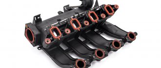
Internal combustion engine cooling systems have been divided into two branches during their development: air cooling and liquid cooling. It is more correct to call a liquid cooling system hybrid, since the fan is used in both types of systems. The medium for dissipating excess heat in the process of removing it from a heated power plant is air. A cooling fan is a device that ensures stable and uniform heat transfer to the environment.
The hybrid cooling system has almost completely replaced the air cooling system in the design of production cars, so further we will talk exclusively about it. It is also worth noting that the function of the fan in both systems is similar. The cooling fan allows for forced and efficient airflow of the engine and radiator of the hybrid liquid cooling system.
We also recommend reading the article about the design of the thermostat for a liquid cooling system. From this article you will learn about the principles of operation of the device, its functions in the system, common faults of the element and methods for eliminating them.
The fan serves to better cool the engine and the fluid in the radiator. This effect is achieved by blowing the internal combustion engine and increasing the flow rate and total mass of air that passes through the cells and fins of the radiator. In most cases, the fan installation location is the space between the radiator and the power unit. The radiator fan itself is enclosed in a special casing.
Types of Cooling Fans
There are four types of fans:
- with direct drive from the timing belt (chain);
- with direct drive from the alternator belt;
- driven by a timing belt or generator and a thermal coupling;
- with electric drive.
A fan directly driven by a timing belt or chain was used on cars that were produced before the nineties of the last century. Moreover, foreign car manufacturers abandoned such a system back in the seventies of the last century. The only dubious advantage of such a drive is the smaller number of belts, because the timing drive covered the pump, fan, crankshaft and camshaft. Often in such systems, the belt or chain was tensioned using a water pump (pump) without installing the adjusting roller.
A fan driven by an alternator belt became more widespread on inexpensive cars produced before the 2000s. Compared to timing belt/chain drive, this system has several advantages. The main one is the lack of influence of the fan on the operation of the timing system. In the event of a fan jam or other malfunctions, the operation of the timing belt is not disrupted and the car can continue to move under its own power.
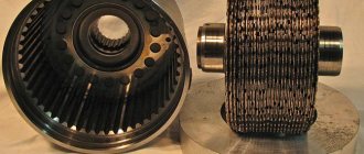
A fan with a thermal coupling, regardless of the type of drive, has the main advantage - it better controls the thermal regime of the motor. Until the clutch is heated, it weakly transfers rotational energy to the fan, so even at maximum engine speeds its rotation speed is low. As the clutch heats up, the transmission coefficient increases and the fan rotation speed becomes increasingly dependent on engine speed. Therefore, when the engine warms up, the fan reduces the temperature of the coolant slightly, and when it heats up close to maximum, its operating efficiency increases.
An electrically driven fan is the most efficient and is used on most modern cars. It turns on only at a certain coolant temperature, thanks to which the engine quickly heats up and operates in a comfortable mode.
Intelligent Engine Cooling Fan Control Relay
After reading mrsom’s post about transplanting microcontroller filling into a retrotachometer from a Zhiguli, I decided to talk about one of my long-standing microcontroller developments (2006), made for smooth control of the electric cooling fan of the engines of front-wheel drive VAZ models.
It must be said that at that time there were already a lot of different solutions - from purely analogue to microcontroller-based, performing the required function with varying degrees of perfection. One of them was a fan controller from the Silych company (what now looks like this, known among those interested in its automatic ignition timing regulator, which software detects engine knocks. I spent some time following the forum of the manufacturer of these devices, trying to determine what turned out well in the device, but not so much, and as a result I decided to develop my own.
As planned, in contrast to existing solutions at that time, the new device was supposed to a) be placed in the housing of a regular automotive relay; b) do not require changes in the standard vehicle wiring; c) have no adjustment elements; d) operate reliably and stably under real operating conditions.
The history of the device and the operating algorithm of the first version was discussed here - for those who do not want to click, I will describe the key things online:
-1. The operating algorithm of the device was assumed to be as follows: the voltage at the standard engine temperature sensor was measured; upon reaching the lower threshold temperature, the fan began to spin at minimum speed, and if it increased further, it linearly increased the rotation speed up to 100% at the moment when, according to the ECM (engine control controller), it was time to turn on the fan at full power. That is, the temperature value corresponding to 100% switching on could be obtained when the device was turned on for the first time, because it has an input corresponding to the output of the standard relay winding. The lower threshold in the first version had to be set somehow, thus drawing a linear control characteristic through two points.
0. At currents of the order of 20A, it is obvious that PWM is used for smooth regulation, and a powerful field switch is used as a key element.
1. Placing the device in a conventional relay housing means there is virtually no heat sink. And this, in turn, imposes strict requirements on the power dissipated by the key element in static (channel resistance) and dynamic (switching speed) modes - based on the thermal resistance of the crystal-case, it should not exceed 1 W under any conditions
2. The solution to point 1 can be either the use of a field driver or operation at a low PWM frequency. Unlike analogues, for reasons of compactness and noise immunity, an option with a low PWM frequency was chosen - only 200 Hz.
3. Operation of the device with standard wiring and temperature sensor inevitably leads to PIC, because The TCR of a standard temperature sensor is negative, and when the fan is turned on, due to the resistance of the common wire and the 'sagging' of the on-board network, the voltage measured on the sensor inevitably drops. It is impossible to stabilize or use a four-wire switching circuit - changes in the standard wiring are prohibited. It was decided to deal with this programmatically - by measuring the voltage on the sensor only at the moment when the PWM switch is turned off - that is, there is no parasitic voltage drop. Fortunately, the low PWM frequency left enough time for this.
4. Programming the device's activation threshold should either be very simple or completely automatic. Initially, the device was equipped with a reed switch, by bringing a magnet to it through the housing, the lower threshold was programmed (the value, of course, was stored in the EEPROM). The upper threshold was set itself at the moment of the first pulse from the ECM. Subsequently, I came up with and implemented an algorithm for fully automatic setting of thresholds, based on finding the thermostable point of the engine (thermostat response point) in the absence of saturation in radiator-to-air heat transfer.
5. The device must provide diagnostics to the user. For this, an LED was added that blinked two bytes in binary code - the current ADC code and the word of status flags.
The device was assembled partly by overhead mounting directly on the terminals of the former relay, partly on a printed circuit board that had turned up from somewhere. The power MOSFET drain output was soldered directly to the relay output lamella, which increased the power dissipation margin. The device worked without glitches on a VAZ-2112 from 2006 to 2010, when I removed it before selling it, and was used not only in the cold climate of St. Petersburg, but also on the Crimean mountain roads (and even on a car in a supercharged version - it was standing on my inlet drive compressor), despite the installation of the prototype level and the controller in the socket.
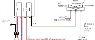
Here is the original diagram (drew only on paper):
And this is a view of the device from the inside:
The device was repeated by several people, one of them (off-roader Gennady Olomutsky from Kyiv) used it on a UAZ, drawing a circuit in sPlan and laying out a printed circuit board - in his version it looks like this:
- the diagram, signet and the latest version of the code are here: https://code.google.com/p/mc-based-radiator-cooling-fan-control-relay
But here is a piece from a correspondence with one of those who repeated this device - in it, for the first time, the algorithm was written out in detail (!) - before that he wrote directly from the brain into the assembler: Now the idea and implementation of the auto-installation algorithm itself (all steps below correspond to unspecified thresholds):
1. We are waiting for the signal to turn on the fan from the ECM (or from the temperature sensor in the radiator in Gennady’s version) 2. We remember the temperature at the moment the signal appears as T1 (we actually remember the ADC channel code for digitizing the sensor signal - let’s call it C1) 3. Turn on the fan at 100% . Set the flag “auto-installation mode is active (bit 3)” 4. After 3 seconds, read the ADC code (let’s call it C1′). This action is necessary in order to determine the amount of compensation for the temperature value due to the influence of the current flowing through the fan and the resulting voltage drop in the measuring circuit on the digitized temperature value. In reality, in 3 seconds the motor does not have time to cool down, but the fan starts and reaches the rated current. 5. Calculate the ADC correction for 100% fan power (let's call it K100 = C1 - C1′). Remember K100. 6. We are waiting for the signal to turn on the fan to be removed from the ECM (or the sensor in the radiator is turned off). 7. Smoothly reduce the power from 75% to 12% by about 1.5% per second. 8. Turn off the fan and wait 60 seconds. 9. We remember the temperature as T2 (ADC code C2). 10. We adjust the lower threshold (increase by 1/8 of the difference between the upper and lower) so that it is above the thermostable point of the thermostat. T2 = T2 + (T1 - T2) / 8. In ADC codes this is C2 = C2 - (C2 - C1) / 8, because The voltage at the sensor drops with increasing temperature. 11. Save C1, C2, K100 in the internal EEPROM of the relay. 12. Set the flag “thresholds are set” (bit 5), remove the flag “auto-setting mode is active”, exit the auto-setting mode to the operating mode
The idea of the algorithm is that it blows through the radiator to the thermostable point of the thermostat, but does not blow strongly so as not to cool the engine by directly cooling the block and head. Then the fan turns off and the relay allows the motor to warm up a little - this way we automatically get the point for the fan to start operating.
During auto-installation, the relay receives a signal from the reed switch during steps 7 and 8 - bringing the magnet to the relay at these moments causes a sequence of steps 9, 11, 12. The threshold is not adjusted in step 10).
If during auto-installation some conditions expected by the relay are violated, the “auto-configuration error (bit 4)” flag is set and the relay exits auto-installation mode. In order for the relay to be able to enter this mode again according to the conditions of step 1, it is necessary to turn off and turn on the power of the relay.
The errors that are caught are as follows: Step 2 - the ADC value is out of range (too low or high). Autoconfiguration range according to ADC code 248..24 (11111000…00011000). In this case, the relay simply does not enter auto-configuration mode without setting the error flag. Step 4 - During the 3 second wait time, the external fan signal is detected to be removed. Step 7 - during a decrease in speed, an active external signal to turn on the fan is detected. Step 8 - while waiting, an active external signal to turn on the fan is detected. Step 11 - the set thresholds are outside the range of 248..24, or the difference C2 - C1 < 4 (that is, they are too close to each other, or for some reason C2 > C1 - for example, when the fan does not actually work and the temperature continues to rise)
Now working mode:
Calculation of the required power (Preq) 1. If the external signal is active - Preq = 100% 2. If inactive, then the current ADC code © and the corresponding temperature T are looked at: T < T2 (C > C2): Preq = 0% T > T1 (C < C1): Preq = 100% T2 <= T <= T1 (C2 >= C >= C1): Preq = Pstart + (100% - Pstart) * (C2 - C) / (C2 - C1), where Pstart = initial power (12%)
At the same time, the required power is not immediately supplied to the fan, but goes through a smooth acceleration algorithm and limiting the fan start/stop frequency. This algorithm works only in operating mode and in the absence of an external turn-on signal: Let Pcurr be the current power of fan 1. If Pcurr > 0 and Preq = 0, or Pcurr = 0 and Preq > 0, that is, it requires starting a stopped or stopping a running fan, then: — The time the fan has been in this state (started or stopped) is shown. If the time is less than the threshold, the fan state does not change. — In this case, if Pcurr > Pstart and Preq = 0, then for the remainder of the running state time Pcurr = Pstart is set (that is, the fan rotates at minimum speed) 2. If step 1 is not fulfilled, or the time spent in the state has passed, then: — If Preq < Pcurr, then Pcurr = Preq is set (then the rotation speed changes downward immediately as the new value is calculated) — If Preq > Pcurr, then the increase in rotation speed is limited from above by approximately 1.5% per second (except for the case when turning on the fan is requested by an external signal) - that is, if Preq - Pcurr > Pdelta, then Pcurr = Pcurr + Pdelta, otherwise Pcurr = Preq
Now about the algorithm for digitizing the ADC value of the sensor and compensating for parasitic feedback during fan operation:
When calculating power, the average value of the current temperature code C is used (see Calculation of the required power), obtained by the arithmetic average of the last 8 values Cm1, Cm2, Cm3... Cm8. Averaging occurs using the “sliding window” method - that is, placing a new value in a buffer of 8 values pushes out the oldest one and causes recalculation of the arithmetic mean C. The ADC cycle (and recalculation of the average) occurs every 640 ms. The “raw” (read from the ADC) Cadc value, before entering the counting buffer, is involved in the following algorithm: 1. It is checked that Cadc > Cdisc, where Cdics is the max. ADC value for an unconnected measurement pin. 2. If Cadc > Cdisc, then the “sensor not connected (bit 6)” flag is set, the value does not fall into the buffer of the last 8 values, and the average is not recalculated. 3. If Cadc >= Cdisc - that is, the sensor is connected, then Cadc is adjusted by a certain amount depending on the current fan power and the correction value for 100% power (see step 4 of the auto-setting algorithm): Cadc = Cadc + Kcurr, where Kcurr = K100 * (Pcurr / 100%). If Kcurr > 0, then the flag “ADC value adjusted (bit 7)” is set. The correction algorithm works only in operating mode and does not work in autoconfiguration mode. 4. The negative dynamics of Cadc are limited in order to suppress sharp decreases in C due to pulse load in the vehicle power circuits common with the temperature sensor: If C - Cadc > Cdelta, then Cadc = C - Cdelta. The limitation does not work during the first 15 seconds after turning on the ignition, so that the correct values Cm1, Cm2…Cm8 are quickly formed in the value buffer. 5. The power and dynamics corrected Cadc value is pushed into the value buffer for averaging as Cm1..Cm8 depending on the current value of the buffer head pointer (the buffer is cyclic, the head pointer takes values from 1 to 8).
Now about LED diagnostics:
The first byte is the “raw” ADC code (in earlier versions the average C value was displayed here). The second byte is the status word. There is a pause of about 1.5 seconds between the first and second bytes. There is a pause of 3-4 seconds between indication cycles. Bytes are displayed bit by bit, starting with the most significant (bit 7, bit 6,... bit 0). A long flash corresponds to a bit set to “1”, a short flash to “0”.
Explanation of the status word: Bit 7 - ADC value is adjusted according to the current fan power Bit 6 - temperature sensor is not connected Bit 5 - thresholds are set Bit 4 - threshold setting error Bit 3 - auto-configuration mode is active Bit 2 - internal processor reset due to freezing - abnormal situation Bit 1 - external signal to turn on the fan is active Bit 0 - purge mode when the engine stops is active
When I described the algorithm, I was surprised how it was possible to cram it into 1024 words of tiny15 program memory. However, with a creak, it fit! EMNIP, there were only a couple of dozen free cells left. That's the power of assembler 
UPD: Many people ask for a link to download the code - here is a link to a page where you can click on Download and get the archive: https://code.google.com/archive/p/mc-based-radiator-cooling-fan-control- relay/source/default/source
Cooling fan malfunctions
The most common fan malfunctions are damage to the blades and failure of the bearings. To repair fans with a belt/chain drive, no matter the timing belt or generator, you need to unscrew the bolts (on some cars, nuts) securing the impeller to the hub and remove the impeller. If the blades are damaged, then it is enough to select an impeller of the appropriate size and holes and install it in place. Replacing the impeller on an electrically driven fan is done in the same way. To replace damaged bearings, you need to unscrew the fixing nut and remove the hub, then remove the bearings, install new ones, lubricate and assemble the entire assembly. If the electric drive bearings are damaged, the entire motor must be replaced. It's easier and cheaper than looking for matching good quality bearings. These procedures are described in more detail in your vehicle's repair manual.
Electrically driven fans
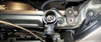
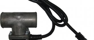
The radiator and engine cooling fan with electric drive has a more complex design than the previous system. In addition, it is more modern, so it is found on many new cars. The device includes an electric motor, a temperature sensor, an electronic control unit, and a cooling fan relay. Most devices have two temperature sensors. One is equipped with a pipe coming out of the radiator. The second sensor is built directly into the thermostat housing, and can also be located in the pipe coming out of the motor. The difference in sensor readings affects the operation of the cooling fan control unit.
We recommend: Basic characteristics of oils for diesel engines
Setting the operating mode of the device's electric motor requires an air flow meter, as well as a sensor that monitors the crankshaft speed. The control unit will receive the corresponding signals from all sensors and process them. The cooling fan relay is then activated, which will monitor the rotation speed of the impeller after the system is turned on. Such devices are often installed by car manufacturers nowadays.
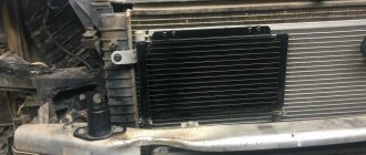
Radiator fans - purpose and design
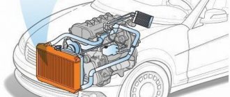
The radiator cooling fan is used for air cooling, which, together with liquid cooling, ensures optimal temperature conditions for the engine. To increase the efficiency of liquid cooling, a radiator is used: oncoming air passes through its cells and cools the liquid. But at low speeds or in city traffic jams, the air flow is insufficient. To avoid overheating, a fan is turned on, which directs air to the radiator, cooling it.
We recommend: Installing the Start-Stop button yourself
On older models and modern SUVs with a longitudinally mounted engine, a mechanical cooling fan drive is used. In older cars it works constantly; later they began to install a viscous coupling, which turns it off if necessary. Used on large trucks and SUVs. The advantage is that it is not afraid of water, unlike electric fans.
Repair of electric radiator cooling fans and heater
Be mobile
Every modern car is equipped with a heating and ventilation system. Thanks to the combined air conditioning and heating mechanisms, motorists and passengers do not depend on the temperature conditions outside the car. The trip is always comfortable.
What to do if systems fail
Repair of electric fans and similar breakdowns will be repaired by an experienced specialist. Thanks to the company’s mobility, the employee will be able to reach the customer in a short time and fix problems. First of all, check the fan terminals. If the voltage is unstable, then the wiring sensor, control unit or wiring integrity is damaged. When the engine “boils” (overheats), the car owner must immediately sound the alarm, otherwise large-scale problems cannot be avoided.
Diagnostic and repair work is not a problem for an auto electrician from a trusted company:
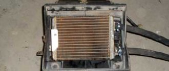
- flushing stove radiators;
- flushing cooling systems;
- troubleshooting or complete replacement of fans;
- replacement of stove radiators and more.
Radiator cooling repair is a frequently provided automotive service, so the restoration stages and the process of replacing parts are brought to perfection. During restoration work, the client receives a number of useful tips on the correct operation of “capricious” devices.
Internal details of the ventilated and heating system:
- filter for purifying air coming from outside;
- deflectors;
- air ducts;
- heater and heater fans.
If you follow the practical advice on-site auto electrician , comfortable travel by car will not be spoiled by unforeseen breakdowns.
Professionalism of the company
In modern vehicle models, specialists know everything repairing radiator This type of restoration work is labor-intensive. Electric fans operate in extreme complexity mode: moisture, dust, temperature changes cannot but have a detrimental effect on the operation of the entire system. In the latest cars, the engine cooling device and the air conditioner are served by only one fan. Such a load will sooner or later make itself felt. Automotive manufacturers consciously make such design decisions in order to reduce the overall cost of production.
Repair of electric fans through a reputable company is always relevant. Complete replacement of the air intake system is quite expensive, so customers ask auto electricians to fight to extend the life of the old factory parts.
Operation of the electromagnetic clutch
The ventilation system is being improved every time. Previously, the air intake mechanism took too much power from the engine due to constant operation. They have been replaced by viscous thermal couplings, which, as the motor heats up, have a more rigid engagement (as the motor operates lower, the rotation speed of the impeller weakens and the rigidity decreases). This operating mode spares the “heart” of the car.
The electromagnetic clutch operates from a temperature sensor. The mechanism has a shock activation, which is a disadvantage. Therefore, this part is used only in a number of foreign car models. It is worth taking into account that the employees of a well-known automotive service know first-hand repair of electric radiator cooling motors
A mobile auto electrician not only has extensive experience, but also state-of-the-art portable equipment. Employee mobility will save client money. The variability of payment for services provided makes communication with the client relaxed. Radiator cooling repairs at an affordable price with a long warranty period are always at your disposal.
Shunting locomotives
On diesel locomotives, electric machines are cooled by air blown through the internal cavities of the machines by fans. Air supply to electric machines can be carried out both from independent fans and from fan wheels mounted on the shaft of the electric machine. In the first case, there is a forced air cooling system, in the second - self-cooling with a built-in fan in auxiliary electrical machines, as well as on some low-power traction generators (TEZ diesel locomotives, TEM type, etc.). Traction electric motors, as well as high-power generators, have only a forced independent air cooling system, since, for example, traction electric motors of diesel locomotives consume high current, leading to intense heating of the windings, precisely at a low speed of rotation of the motor armatures, at which the fan wheel mounted directly on armature shaft would not be able to supply the required amount of air to remove the generated heat.
Cooling of traction electric machines can be carried out by individual fans, group fans, as well as one fan with a centralized system for supplying cooling air to all electric machines and devices. Diesel locomotives usually use centrifugal fans. With a centralized air supply system, axial fans are used.
Centrifugal fans. The fan (Fig. 164) consists of a welded housing 6 with a suction central side opening and a discharge channel connected by an air duct to the ventilation cavities of electrical machines. A fan wheel rotates inside the housing, consisting of two disks 4, 11, interconnected by blades 5 attached to them. The blades are made by stamping from a clad duralumin sheet and subjected to special heat treatment. One disk of the fan wheel is connected by rivets to the flange of the hub 1, the shaft 2 of which is driven into rotation.
Gearbox of the centrifugal cooling fan of the traction generator of a diesel locomotive 2TE10V. The centrifugal cooling fan of the traction generator is driven into rotation by a gearbox, the shaft of which is connected to the upper crankshaft of the diesel engine. The cast iron housing 1 of the gearbox (Fig. 165) contains 7 driving and 8 driven shafts with bevel gears.
Rice. 164. Centrifugal cooling fan for traction motors:
) _ hub; 2 - shaft; 3 - oil seal; 4—carrying disk; 5 - shoulder blade; 6 — body; 7 — sleeve; 8 - frame; 9 - pipe; 10 - gaskets; 11 — disk mi. The drive shaft rests on 3 roller and 4 ball bearings, held against axial displacement by a cover. The cover, together with the labyrinth ring, bushing and felt ring, forms the labyrinth seal. Drive flange 5 is pressed onto the conical shaft shank. To dismantle flange 5, an oil drain is provided. When removing oil, oil is pumped through a hole by a press
Rice. 165. Traction generator cooling fan gearbox:
frame; 2 - bevel gear; 3, 4 - bearings; 5 - flange; c - cover; 7 - drive shaft;
8 driven shaft in the hub, pressed onto the shaft, into an annular groove on the shaft, thereby reducing the unpressing force.
The driven shaft 8 is installed in the longitudinal bore of the gearbox housing and rests on roller and ball bearings. The driven shaft has a labyrinth seal with felt rings similar to the drive shaft. The hub of the fan wheel is attached to the conical shank of the driven shaft, which is interchangeable with the wheels of the engine cooling fans of the front and rear bogies. Gears and bearings are lubricated by splashing oil during gear operation.
Centralized air cooling system for electric machines and diesel locomotive devices TEP70. The centralized air cooling system (Fig. 166) provides cooling air to the traction generator, traction electric motors, rectifier unit, as well as to the equipment chamber to maintain excess air pressure in it, preventing dust from entering the chamber. An axial fan sucks air from the atmosphere through filter unit cassettes and pumps it to consumers through a system of channels located in the frame of the diesel locomotive.
The fan is connected to the inlet manifold installed in the roof of the locomotive by a canvas sleeve, secured to the fan body and the inlet manifold with metal clamps. The fan is bolted to the lower part of the diffuser, made in the frame of the diesel locomotive and being the strength element of the frame structure, through adjusting shims and a sponge rubber seal.
Air channels to the traction generator, rectifier unit, traction motors of the front and rear bogies are also included in the power structure of the frame. All air ducts are box-shaped, welded and made of sheet steel. Air channels to the traction motors, traction generator and rectifier unit are connected through canvas sleeves.
Rice. 166. Centralized cooling system for traction electrical machines and devices:
1 - axial fan; 2 — channel to the traction generator; 3, 4, 7, 12, 13, 16 — channels to traction motors; 5 — channel to the heaters of the driver’s cabin; 6 — channel to windshields; 8 — diesel locomotive frame; 9, 14 - main frame air ducts; 10 — filter block; 11 — channel to the rectifier unit; 15 - channel to the hardware camera
The fan (Fig. 167) has two housings. The upper housing contains the flow part of the fan. The prototype of the flow part is the TsAGI-K-42 axial fan model. The fan is made according to the following scheme: guide vane, impeller, straightener. The diameter of the flow part is 780 mm. The disk and blades of the impeller 4 are made of aluminum alloy AK.-6. The blades (16 pcs.) are installed on the disk at an angle of 40° and secured with a dovetail lock and locking plates. The guide vane 5 has thirteen blades. The blades consist of two parts: a fixed one, made integral with the cast body, and a rotating flap made of U2-301-07 phenolic plastic. Rotation of all blade flaps simultaneously is carried out using a rotating device 3 mounted on the fan housing. Is-
the forward position of the guide vane flaps is 90°. By changing the angle of the flaps, the pressure and flow of the fan are adjusted.
An increase in pressure and air flow occurs when the rotary device handle is moved towards the “+” sign on the dividing sector, a decrease - towards the “-” sign. The straightening apparatus 2 is of welded construction, made of sheet steel 20 and has 15 stamped blades installed at an angle of 75°. The second lower fan housing is the axial part of a diffuser with a ring-shaped cross-section, divided by partitions into sectors, the areas of which are proportional to the amount of cooling air for each consumer.
The radial part of the diffuser is made on the frame of the diesel locomotive, being at the same time a load-bearing element of the frame. A step-up bevel gearbox is mounted in the fan housing, transmitting rotation from the traction generator to the fan wheel. The gears of the angular reducer 9 with spiral teeth are made of 12ХНЗА steel with carburization and hardening of the tooth surface. Drive shaft 1 rotates in two roller bearings installed in a common cup. The axial load is taken by the ball bearing. A bevel gear 9 is pressed onto one of the conical ends of the drive shaft, and a flange of an elastic coupling is pressed onto the other. The driven shaft 7 is made together with the gear and rotates in two roller bearings. The axial load is carried by the ball bearing. The bearings are installed in a common cup. The fan impeller is pressed onto the conical shank of the gear shaft. The tapered shaft shanks are equipped with internal threads and channels for supplying oil when pressing and unpressing the flange, gear and fan wheel using a special device.
The bevel gear is forced to be lubricated. The drive shaft, through a driver, rotates a 10-blade oil pump mounted in the fan housing. Oil from the gearbox housing is supplied through a strainer through channels in the housing through nozzles and jets to the gears and bearing units.
The oil level in the fan crankcase is checked with a dipstick. The oil pressure is controlled by a pressure gauge and should be within 0.15-0.6 MPa. The fan gearbox uses rubber (round cross-section) and labyrinth non-contact seals for bearing units.
Air purifier for centralized air supply system. The air cleaner (Fig. 168) is a part of the body roof in which twenty-two cassettes 3 are located. Air drawn in by an axial fan passes through the cassettes. The cassettes are installed inside the roof frame and in the cross section of the diesel locomotive they form an arch, inside of which there is a suction pipe 5 of the fan and a hatch 6, which serves to blow the cassettes with compressed air to clean them when they become dirty during the operation of the diesel locomotive. There is a special hatch for inserting and removing cassettes. The cassettes are inserted into the grooves and pressed by hand with screws 4. The screws are secured against spontaneous unscrewing with locknuts.
All cassettes in each row are removed through the seat of one cassette of this row. The hatches through which the cassettes are inserted into the air purifier are hinged and open inward. Each hatch is secured in the open state by two spring latches located on the wall of the locomotive body. Contamination of the cassettes is monitored by a differential pressure gauge mounted on the outer wall of the air cleaner.
The air purifier cassette (Fig. 168, b) consists of an outer 12 and an inner 10 housing, mesh 8, 9, packing 7 and seal 11. A mesh 9 is attached to the outer cassette body, which, together with mesh 8, protects the packing from blowing out and damage.
Fan clutch. The torque from the diesel shaft to the fan of the centralized air supply system is transmitted through an elastic coupling (Fig. 169). Elastic
Rice. 169. Axial fan clutch:
1 - rubber cord shell; 2 - rings; Z, Z - bolts; 4 - flanges The element of the coupling is a rubber cord shell 1 measuring 500X150 mm with ten layers of cord. The shell on each side is clamped in two rings 2 made of 40X steel, connected to each other by ten bolts 5 made of 40XC steel. The inner rings of the coupling consist of two halves and are centered on the hole in the outer rings. Flanges 4, pressed onto the tapered ends of the diesel shafts and the drive shaft of the fan gearbox, are attached to the outer rings of the coupling with eight bolts 5 each. The relative position of the flanges and rings is fixed by centering bands and two pairs of conical pins.
⇐ | Power take-off from a diesel engine to drive auxiliary equipment | | Diesel locomotives: Mechanical equipment: Construction and repair | | Speed meter drive | ⇒
Why the fan doesn't work Let's figure it out
Wiring and contact. Any of these reasons, despite their harmlessness, can be the reason why the fan simply does not turn on at the right time. It also often happens when the reason lies in the malfunction of the electric fan motor itself, which for one reason or another cannot start working. In cases with the electrical network, I would recommend finding an experienced electrician who will empirically determine the fault and answer the question of why the cooling fan does not turn on. Fuse. A blown fuse can also be attributed to common causes that occur quite often. An open circuit due to a blown fuse will prevent the electric fan from turning on, resulting in an increase in engine temperature. You can check the fuse very simply, just remove the fuse that is responsible for the operation of the fan, and replace it with a new fuse or simply insert a piece of wire in such a way as to close the circuit. If during the test the electric fan starts to work, then the reason is in the fuse. Air lock or low coolant level. Check the coolant level and the cooling system hoses. At operating temperature, the hoses leading to the radiator should be hot and the coolant level should be correct in both the expansion tank and the radiator. Be careful, check the antifreeze level only on a cold engine
Also, if the fan does not work, you should pay attention to the circulation of antifreeze; after warming up, it should circulate in a large circle. If this is not the case, there may be an air lock in the system; read how to remove it here
A decrease in coolant level may indicate a leak in the cooling system. In the best case, it will be a question of replacing the cylinder head gasket, in the worst case, a crack in the block or a burnout... Temperature sensor. Thanks to this sensor, the electronic unit (ECU) decides whether to turn on the fan or not. Unstable operation or malfunction of this sensor will lead to the ECU receiving incorrect information about the coolant temperature, as a result of which the fan will not turn on. The last suspect is the thermostat. If it is faulty, the circulation of antifreeze will be difficult, as a result, the operation of the fan will be compromised. For example, when the thermostat is stuck on the “small circle”, the fan does not turn off and runs constantly, because the engine is warmed up, the temperature rises and the fan tries to fix it all. The only problem is that due to the stuck thermostat, the liquid in the radiator does not circulate and cooling does not occur. In some cases, the opposite happens: the temperature sensor does not work, because a jammed thermostat does not allow liquid to pass through a large circle, and as a result, the electric fan does not turn on.
Popular:
How did this device appear?
The very first person to come up with the idea of creating such a device as a radiator cooling fan was Wilhelm Maybach. Back in 1886, the first automobile prototype of the Benz-Velo appeared, which was the progenitor of the current scheme.
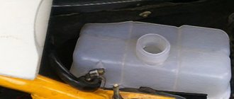
We also note that any car needs a radiator fan; on its cover, it has a warning sign that says that you should not open the cap until the device has cooled down. Otherwise, injuries are possible, because steam from hot antifreeze can escape under high pressure. The car radiator has a temperature sensor; it is thanks to this device that you can monitor the operation of vital engine systems.
Previously, ordinary water was used instead of antifreeze. It had to be forced to move along the jacket, cooling the engine. At the same time, a water pump was not yet used; at that time a thermosyphon was used, which drove water through the engine. The temperature sensor was also missing, at that time everyone read the creepy inscription, which informed about the danger of opening the cover of the device.
The radiator of the cooling system worked according to the laws of physics. That is, when the water was heated, it rose higher, and the cooled liquid fell lower, cooling the engine. The liquid that rose higher moved through the pipe, where it again acquired a low temperature and fell down to the engine.
When the engine power increased significantly, the use of the thermosiphon stopped, as it showed a low efficiency. Over time, engineers switched to pumps that provided greater pressure, causing the fluid to quickly move through the pipes from the radiator to the engine.
https://youtube.com/watch?v=zf7p8ubmKxw