How to create a sound amplifier correctly
First of all, to assemble such a device for speakers, you will need tools, as well as the required components. Circuits of the simplest amplifiers are assembled using a soldering iron mounted on a support with a high degree of stability. It is advisable to use certain soldering stations.
In the process of assembling an amplifier with your own hands for testing the corresponding circuit, or using it for a short period of time, a model on a wire would be a good option, but it will require a lot of free space to arrange the component elements.
The printed circuit board guarantees maximum compactness of the device and convenient use in the future.
A popular and affordable amplifier, intended for headphones or small speakers, is made on the basis of a microcircuit that represents a small-sized control unit with a built-in set of commands for controlling the electrical signal.
A pair of resistors and, of course, capacitors should be connected to the circuit with the desired microcircuit. In total, the price of an amplifier assembled by yourself will be much lower than the cost of equipment purchased in a specialized store, while the limitation of functionality is changing the volume of the signal.
Do not forget about the features of single-channel amplifiers, the independent production of which is carried out on the basis of both TDA circuits and their analogues.
The circuit generates a lot of heat during the working process; it is for this reason that its contact with the elements of the device should be minimized. A radiator grille designed for heat dissipation is desirable for use.
Depending on the purchased microcircuit, as well as the power of the device, the size of the required radiator increases. When assembling the amplifier inside the housing part, you need to think in advance about the space provided under the heat sink.
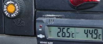
Another feature of creating an amplifier with your own hands, as shown in the photo, is the minimum power consumption, which makes it possible to use a simplified amplifier in cars, on the road, or at home. Some simple amplifiers require only a few volts.
The power consumed directly depends on the required level of signal amplification. The audio amplifier from the player used for the required headphones consumes approximately 3 W.
To make circuits, it is better for an inexperienced radio amateur to use a special program for which the files have the required extension.
Creating the necessary circuit yourself is possible if you have certain knowledge and the desire to experiment with it. Otherwise, it is better to download files for quickly assembling a replacement amplifier of the lowest possible frequency.
Do-it-yourself speaker amplifier for the car
This circuit is designed to reproduce audio frequency signals from a car radio, FM tuner or other electronic device. The variable resistor at the input can be a volume control for a sound-reproducing device. Preliminary signal amplification is performed by a two-channel 548UN1A microcircuit. The pins for the second channel in the manufacture of a stereophonic path are indicated in brackets. The integrated circuit is characterized by a low noise level, a large supply voltage range (6-30 V) and low current consumption. The bass reflex is assembled on two germanium transistors of different conductivities. Reliable transistors of older series can be replaced with more modern analogues.
The signal from the bass reflex collectors is supplied to the semiconductor bases of the output stage. By reducing the capacitance of capacitor C4, you can limit the reproduction of low frequencies. By selecting resistor R4, on the collectors of the output transistors, you need to set half the supply voltage. Powerful transistors are mounted on a common radiator. The input circuits entering the input of the integrated circuit must be shielded. When installing the device on a car, it is necessary to take into account the correct connection of the common wire. “Ground” is made with a thick and as short as possible wire.
You can make a do-it-yourself sound amplifier for a car using a bridge circuit. It does not contain scarce parts and is designed for high-quality sound reproduction in the car.
The design receives power from the on-board network and provides an output power of 12 watts into a 4 ohm load. The capacitances of capacitors C4 and C5 should be about 2000.0 microfarads. In this case, the unit will reproduce a frequency band from 25 Hz to 18 kHz, with a nonlinear distortion coefficient of no more than 0.3%. Silicon diodes set the quiescent current of the output transistors. The power supply circuit contains a fuse and a choke. This is a single-layer winding with PEV wire with a diameter of 1 mm on a ferrite rod 20 mm long and 8 mm in diameter. The following radio components are used in the circuit:
- DA1.1 – DA1.2 – K548UN1A
- VD1 – VD8 – KD521A
- VT1 – VT7 – KT503A
- VT2 – VT8 – KT502A
- VT3 – VT5 – KT819A
- VT4 – VT6 – KT818A
For laptop
The instructions on how to make an amplifier for a laptop with your own hands provide for assembling such a device in such cases: the built-in speakers are broken or have low volume quality.
You will need a regular amplifier with a power of several watts and a winding resistance of 40 ohms. In addition to the usual tools, assembly requires a printed circuit board, power supply and microcircuit. Choose your own housing where the amplifier elements will be located.
The assembly process should depend on the downloaded chip format. The radiator is selected in such a way that thermal conductivity makes it possible to maintain the required temperature regime of the microcircuit.
If the device is constantly used along with a laptop outside the room, then it will need a self-made case with certain slots or holes so as not to impede air circulation.
Immersion blender - which company is better to choose for your home? Photo+video reviewsDIY tester: instructions, diagrams and solutions on how to make a simple homemade device. Step-by-step instructions on how to make a tester from a smartphone
DIY voltage regulator: master class on how to make a simple voltage regulation device
Such a case is assembled from a plastic container or the remains of failed equipment, and the board is secured with screws.
DIY mini amplifiers for cars
If high output power is not required, then you can make a sound amplifier for your car using inexpensive integrated circuits. One of the possible options is made on the TDA2003 integrated circuit. Its complete analogue is the popular domestic microcircuit 174UN14. The device operates from the vehicle network and provides an output power of up to 10 watts into a 2 ohm load or 6 watts into a 4 ohm load. Frequency range from 40 Hz to 15 kHz. The chip should be installed on a small radiator.
Tube amplifier
This DIY amplifier, as in the photo, is a fairly expensive device if you buy all the components.
Some radio amateurs have lamps and other necessary parts in stock. Assembling a tube-type amplifier at home is considered not a difficult task if you can spend time searching for the necessary circuits on the RuNet.
If you need to find out what types of amplifiers there are, it is important to understand that their circuit in each individual version is unique, and also depends directly on the sound source, size, and other important parameters.
Powerful DIY car amplifier
The modern element base allows you to independently produce a sound system of sufficiently high power with a minimum number of radio elements. Integral components are used for this purpose. You can make a powerful amplifier in your car using the TDA1562Q chip. This integrated circuit provides a voltage doubling function, which allows the amplifier to develop high output power when powered from the vehicle's on-board network. The design allows you to get up to 70 watts into a 4 ohm load. The circuit has protection against short circuit of the output and short circuit of any of the output wires to positive or body. When the case heats up above 1200C, the device will automatically switch to a reduced power mode, which will not exceed 20 watts. The TDA1562Q chip has the following characteristics:
- Supply voltage – 8-18 V
- Frequency range – 18-40,000 Hz
- Input impedance – 100-120 kOhm
- Output power – 55-70 W
- Nonlinear distortion coefficient at 20 W power – 0.06%
An LED is included in output circuit 8, which lights up when the temperature exceeds the norm, there is a break or short circuit in the load or another emergency situation. Capacitors C7 and C8 consist of two capacitors of 3,300 microfarads connected in parallel. Through the contact block connected between the 4th pin and the power plus, you can control the switching on of the device. To do this, you need to connect any latching switch to the contacts of the block. Capacitors C3, C4 and C6 must be film. The microcircuit is mounted on a radiator with an area of at least 600 cm2. The surface of the microcircuit should be lubricated with KPT heat-conducting paste. A 15 A fuse is placed between the “+” of the battery and the amplifier’s power bus. The input signal, through capacitor C3, is supplied to the input of microcircuit 1 (IN+), and the speakers are connected to pins 7 and 11 (OUT+, OUT-).
This simple stereo circuit contains a minimum of parts and provides up to 40 watts per channel into a 4 ohm load. The device is assembled on a TDA8560Q chip, which is operational at a supply voltage of 8 to 18 volts. It provides a signal gain of 46 dB in the range from 10 Hz to 40 kHz. The distortion factor at a frequency of 1 kHz and an output power of 20 watts does not exceed 0.1%. If the signal is taken from the input of the terminal stage built into the radio, then it should be supplied through resistors with a resistance of 20-50 kOhm. If the signal is supplied from a speaker, then the resistor value should be 150-200 kOhm.
How to do it yourself
You can make a sound amplifier in a car yourself using ready-made kits. This will simplify testing and adjustment, and reduce the likelihood of errors that could lead to incorrect operation. Another advantage is that no radio engineering skills are required.
The kit for self-assembly of an amplifier consists of blocks of a limiter, preamplifier, power amplifier, crossover, stabilizer and control device. Another option is to assemble the device from discrete parts according to the diagram.
Frame
It must provide adequate cooling to amplifier components that may become hot during operation. To do this, slots or holes should be provided, which should be located as close as possible to the output chip. To improve the cooling of the powerful amplifier, a 12 V fan is installed. It will provide additional protection against overheating.
The housing can be made of plywood or metal, such as sheet aluminum or tin. In this case, it is necessary to ensure the isolation of the components and the device board. To improve shielding, you can connect the negative pole of the board to the case. It needs to provide seats for terminals that are attached to the reverse side. To avoid mistakes when connecting, explanatory notes should be placed on the housing.
Speaker amplifier
First, it is recommended to make a power filter with a fuse. Its rating is at least 20 A. The filter itself includes a choke, which can be taken from a faulty radio, and capacitors. They are combined into a battery to improve operating efficiency.
The filter capacity must be at least 6000 µF. The larger it is, the better the amplifier will perform at high volume. To automatically turn on the device, a mechanical or electronic control relay must be installed. The winding is connected to ground and the blue and white stripe wire of the radio. The contacts are connected to the positive wire gap in front of the filter capacitor.
If you are assembling a car sound amplifier with your own hands from a ready-made kit, then you should connect the blocks in accordance with the instructions. The amplifier and preamp are connected to each other using the included cables. A power stabilizer or voltage converter is connected to these blocks if more than 14 V is needed for normal operation of the microcircuit.
After this, the assembled structure is installed in the housing and secured with the elements included in the kit.
If the amplifier is assembled on a board from separate parts, then you will need to solder them to the required points. When connecting this device directly to the speaker outputs of the radio, it is necessary to provide an adjustable divider. It is not required if the connection is to a low level line output. Wire resistors necessary for protection and matching are included in the speaker terminal gap. Their resistance is 1-2 ohms.
Subwoofer amplifier
It is distinguished by the greater power required to drive the subwoofer, as well as the presence of a low-pass filter. The amplifier chip is installed on a heat sink with a larger area for more efficient cooling.
The sound power of the subwoofer can be increased by connecting it using a bridge circuit. If you need an amplifier in your car for both speakers and a subwoofer, then each channel has its own unit. The entire structure fits into 1 housing.
I assembled the AC protection according to this scheme
There is no need for configuration if everything is assembled correctly. Printed circuit boards will be archived. When testing the amplifier, I removed 98 watts from one channel, then it went into clipping. As the author stated - pure 100 watts. I used radiators from a computer, from an AM 3+ socket. Without coolers it gets damn hot because the radiators are too small. I decided to leave the cooler running - now everything is warm. The cooler was powered using a PWM regulator circuit using an NE555 timer.
Next, I started assembling the second converter for the subwoofer channel. The scheme remains the same. There are minor changes to the winding of the transformer. I used the same rings, two glued together. The primary remains the same. But the secondary is different, the number of cores is the same, but there are no longer 15, but 21 turns. The output of the converter turned out to be +-70 volts. For the low-pass filter, I wound a separate winding with 0.8 8 turns wire. The stabilization circuit remains as in the circuit. There is also another winding to power the AC protection, everything is the same as in the first converter for Laikov.