Good day everyone, Friends and just Guests! Maybe the topic is not new, but still, sooner or later we all face this problem. I kept thinking for a long time about the point of installing additional mass? Let me remind you a little how it all started and why it made me think about installing additional weight on the car body
Then I saw a post by viktor53rus
New additional mass that he installed additional mass
And then I thought about it a little, why not put additional weight on the body, start small, if this doesn’t help then we’ll look for the reason elsewhere
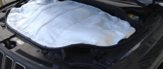
Almost 100%, you can even say 200% - on modern cars, the body is used as a single source of electricity. The car body is like a universal wire with a negative charge for all consumers of electricity. That is why the body is called the painfully familiar term “mass.” And why “painfully familiar”? Yes, because if somewhere the contact with the ground is either poorly secured or oxidized, after the first measurement I began to look for the reason, I started with the simplest where the weak “mass” places are on the VAZ 2114 2113 2115 with 1.5 liter engines. I’ll try to describe the places in which are most likely to result in the loss of a reliable connection to ground, and the glitches that appear in this case. This is the mass of the battery.
The “minus” on the battery has two branches: a thick wire and a thin one. A thick wire runs from the battery negative to the engine housing. If this contact is not secured properly, then the battery is not fully charged, the starter does not develop full power, and the ECM stalls (because it takes weight from the engine)
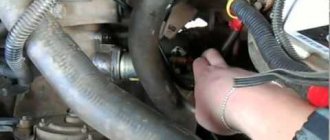
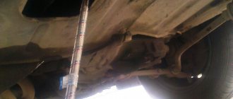
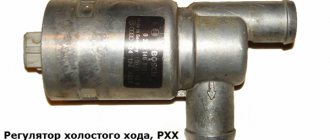
On the negative mount of the battery with the engine, you need to check the tightness of the two nuts between which the contact to the engine is attached: first of all, loosen the outer nut and tighten the inner one, and then tighten the outer one. The second wire from the battery is much thinner and is attached to the body next to the battery itself. This wire is the source for all energy consumers in the car. Here you also need to check the tightening torque of the nut both to the body and to the battery terminal. Look at this whole thing and if there is oxidation, then you need to clean it down to white metal and screw the whole thing back. Then we go to look further where the mass is attached. ECM mass in Samar 1.5 l engine, the mass for the ECM is taken from the engine housing, from the fastening of the plugs. The plugs are located on the right side of the block head
View from above
Number 1 is the ground where the ECM wires are attached, and Number 2 is where the engine ground is attached.
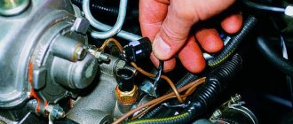
In practice, it happens that this pin No. 1 is painted at the factory and is loosely tightened. Therefore, over time it may become loose and at the moment the fan is turned on, there will be a drop in the voltage of the following sensors (which will lead to jumps in speed): DTOZH, TPS, MAF.
that absolutely all factory-made studs are not treated in any way other than paint, so over time corrosion, oxidation appears, and voltage drops begin. After all these inspection measurements, it was decided to put additional weight on the car body. A little history of how to do it And so I had a copper one in stock (why is it copper and not steel, since copper is the best conductor of current, because copper wires are installed on the starter and on the generator) wire with a cross-section I may be wrong, but I won’t say everything is in the photo
Then I measured my diameter with a caliper
to buy terminals. I bought terminals of the required diameter
They froze too
Then I stripped the wire
I put the terminals on and began to tighten them in a vice, since I don’t have a terminal press
Ready-made version This is how the jumper turned out
Then, to the heap and to calm the soul, the ends of the brands that connect the wires were covered with tin, put on heat shrinkage and wrapped it with electrical tape on top of the heat shrinkage, in the future you need to buy additional corrugation and put the wire in the corrugation for beauty =) When everything was done, I went to install it on the car. Additional mass can be installed6 - Generator - engine - engine., Body - generator stud., Body - negative battery terminal. Engine - Rack housing or for a more convenient place where you can put it yourself
Then I took measurements on B.K. at idle it now shows 14.2v-14.4v. Previously it showed only 14.0 -13.8 V
I turned on the low beam at idle on the B.K. Now it shows 14.1 V, before it was 13.6 V
And finally, I decided to turn on all the instruments, low beam headlights, hazard warning lights, heater motor at 3rd speed, heated rear window, two heated seats, heated mirrors, video recorder, fog lights, reverse gear, car charger for the phone, music .It showed 12.8 at idle before and B.K. was already beeping. and showed 10.3 V
then, having removed 2 seat heaters, the voltage has already increased from 12.8v to 13.1v
In general, this additional weight on the car body is fully justified
And so let's sum it up:
The drawdown disappeared, the charging returned to normal, I should have immediately looked at all the ground connections on the car body, and not thought about what the problem was =), plus add additional ground and the problem could have been solved right away. Yes, and I noticed that now it’s working smoother at XX and maybe it seemed or Already self-hypnosis the car began to pick up speed better.
Don’t blame me for the photo, maybe it’s hard to see, I took it from my phone, and I didn’t take measurements with a digital Multimeter because I forgot it, although everything was visible and clear on the B.K., if necessary, I can write down the readings on it.
I think maybe someone will find this article useful and will not draw hasty conclusions.
THANK YOU VERY MUCH for your attention!
GOOD LUCK ON THE ROAD everyone! PEACE FOR EVERYONE!
Power supplies
On the vast majority of modern cars, the power source is a three-phase alternating current synchronous generator driven by the main engine; three-phase alternating current from the generator is supplied to the built-in three-phase rectifier and voltage regulator circuit - in modern cars the voltage regulator is built into the generator housing. A car battery is used to provide constant and continuous power to some consumers when the engine is not running, such as lighting, car radio, brake lights, anti-theft alarm, as well as to fully power all vehicle systems when the engine is started. After starting the engine, the battery is recharged from the generator, and then it works in a buffer with the generator, smoothing out voltage drops when connecting powerful consumers. The generator power of a modern middle-class passenger car ranges from about 900-1300 watts.
How to connect the vehicle's ground switch? And this can be done
A common question is how to connect the car's ground switch. After all, not every modern car has such a useful function. And people regularly encounter dead batteries after parking for several days. After all, a car has a lot of different equipment that is constantly connected to the battery. And even in economy mode, energy consumption is constant. Also, the risk of electrical equipment breakdowns and current leakage through damage to the insulation cannot be excluded. In all these cases, such a switch will not be superfluous, so experienced car enthusiasts recommend installing such a device in the car.
Electricity consumers
Vehicle systems, depending on model and configuration:
- ABS - anti-lock wheel system (anti-skid automatic braking)
- SRS - safety system (airbags, belt tensioners, etc.)
- EFI, ECM - electronic engine management systems
- Electronically controlled automatic transmission
- Trip computer
- and other
Lighting devices
Main article: Car lighting devices
Automotive lighting devices are divided into external and internal.
- External ones include headlights (with low and high beam), side lights, turn indicators (combined with hazard warning lights), brake lights, reversing lights, license plate lights, fog lights, contour lights, spotlights, and in some cases decorative lamps.
- Internal lamps include interior lighting lamps, engine compartment lamps, trunk lighting lamps, glove box lighting lamps, instrument panel lighting lamps, etc.
Other consumers
- Starter
- Ignition system
- On-board computer
- Electric power steering
- Fan motors, windshield wiper drives, power windows, etc.
- Heated glass
- Parking sensors (parking sensors)
- Reversing cameras
- Seat servos
- Cigarette lighter
- Radio (radio), TV, multimedia entertainment system
- Sound signal
- Anti-theft alarm
- GPS navigator, built-in or separate,
- Seat heaters,
- as well as other auxiliary and information systems and devices.
Some types of household appliances, also adapted for use in a car, can receive power from the car's electrical network (connection is made either through a special socket or through the cigarette lighter socket). For this purpose, various adapters are used - from the simplest voltage dividers to switching power supplies with double current conversion. But the cigarette lighter socket was not initially designed to connect consumers other than the heating element of the “electric lighter”, so blown fuses and thermal damage to the socket are common (it is necessary to calculate the permissible current consumption based on the cigarette lighter fuses).
On some machines with powerful generators, an inverter with an output of ≈ 220 Volts can be installed to power ordinary household appliances. Powerful special-purpose machines may have other networks with other supply voltages.
Is the weight on a car a plus or a minus?
I was prompted to write this article by another incident when I needed to use “lighting” - to start the engine from the battery of another car. Every time I do this I am faced with the illiteracy of other drivers. And this time, when I reasonably explained why and how to do it, the driver said that he was an electrician. I didn’t argue, let him be an electrician...
So, there are two main misconceptions when lighting a cigarette: 1. You must connect the minus (ground) first, then the plus. 2. Apply the gas (keep the speed above XX) when starting another car.
Let's deal with the first one. I always wondered why they so insistently wanted to connect the masses first. All I hear in response is “well, that’s a lot.” The last time I received the answer “I’m an electrician”) In fact, for low-voltage car networks, there is no difference what to connect first - plus or minus. Moreover, the cars are reliably isolated from each other by the thickness of their rubber tires. You can safely connect the positive terminals of the battery first. The advantage of the connection sequence, first plus, then minus, is security. If you first connect the minus (mass), then everything they say is true, the mass of the cars becomes common, all the hardware of both cars becomes connected to the minuses of both batteries. Therefore, when you then connect the positives, you need to be very careful; accidentally touching the positive wire with a loose clamp on any hardware of both machines will cause a short circuit and decent fireworks. With or without consequences, depending on your luck. If you connect the plus before combining the masses, then everything is much simpler. One end of the wire (positive) is led out of the car in advance to which the wire will be connected first. Then it is freely connected to the positive of the second car without fear of touching its iron (ground). The masses of the cars are not yet connected, there will be no short circuit. Then the negative (we connect ground) wire is connected without any worries. To create a short circuit with such a sequence, you need to make a special effort.
Second misconception. It is believed that if you apply the throttle (keep the revs up) while trying to start, the second car will start better. In principle this is true, the generator will add several hundred watts. Perhaps, as a last resort, this option will be the only one. But unless the case is extreme, why subject the generator to a load for which it is not designed? During a cold start, the starter can draw hundreds of amps. Generators and wiring of passenger cars are not designed for such currents. And the more revolutions you add when trying to start, the more the generator will be loaded. Burnt diodes in a generator can be easily obtained. Therefore, it is better to try to start the second car by completely turning off the engine. Before starting, of course, you can let the generator run to charge the battery of the car being started. Then turn it off and try to start it.
All ground mounting points for the VAZ of the tenth family
| If the electrics in the car start to malfunction, then one of the reasons for this ailment may be poor fastening of the battery mass. Ten have features of mass fastenings depending on the engine and year of manufacture of the car. We check all the attachment points of the negative wire: |
Location of masses in the car interior
| 1 - fuse block.2 - near the driver’s right foot there is a shield, which is attached with a couple of screws, removing it, you will see that everything is like in the picture.3 - in principle, the situation is similar to the point described above, except that the shield is located next to with the left leg of the navigator. |
| The stud in the dashboard behind the mounting block, in order to find it, you need to bend in a certain way. The headlight hydraulic corrector is shown there for reference; the ground pin is located above and to the left of it. Through this mass, the windshield wipers, heater fan (21124) and door lock activators are powered. |
| The console is on the right side, from here it is more convenient to check the very important ground pin, through which the bracket under the ECU is connected to the car body, and accordingly the reliability of the ground of the ECM and the cooling fan depends - this nut also holds the corner that supports the far part of the left panel of the console. |
| ECM harness mass crimps in the console. The connector was removed from the ECU and pulled out onto the driver’s mat, it’s more convenient. I bit the fan ground wire out of the ignition circuit crimp (left in the photo), extended it, put the tip on and connected it separately to the bracket. I soldered all connections for reliability. |
| Weight of the Electric Fuel Pump (EFP) module and fuel level indicator. A black and white wire is attached to the left rear handbrake lever mounting bolt under the floor tunnel. The fuel pump is powered through this mass, and the accuracy of the fuel level reading also depends on it. |
| The ground is on the stud of the fuel pump flange; this wire most likely connects the pump housing to the fuel filter bracket and this was done for safety reasons to equalize the potentials of these two devices. |
It is easy to find the ground of the electric fuel pump module without removing the tunnel; just fold back the mat, slightly bend or carefully trim the carpet of the floor behind the driver's seat below the ashtray of the rear passengers, without damaging the ground wire itself. Then the carpet easily falls into place and the cut is almost invisible.
Location of masses under the hood of a car
The battery terminal is large and thick with a large cross-section wire (approximately 16 sq. mm). Its thick part, about the thickness of a little finger, connects the negative battery and the engine. If the contact of this wire is unreliable, there may be a deterioration in the battery charge, a decrease in the starter rotation speed when starting, as well as problems in the ECM system, because the minus comes from the engine, from the studs on which the ignition distributor hung on carburetor cars.
| The thin wire connecting the minus battery and the car body is the main connection for all electricity consumers in the car, and in carburetor modifications also for the engine. Through this connection, all the car's lighting equipment, radio and other devices are powered, depending on the year of manufacture of the car. |
| The connection point for the negative terminal of the battery to the engine block is connected to the upper stud of the thermostat, if you look behind the air filter. The cross-section of the wire was chosen based on the large current consumption of the starter; this wire can easily be traced by hand if it is led from the battery. The starter current flows through this wire, charging the battery, some sensors screwed into the engine block are connected through it |
| Nearby there is another ground connection point to the engine block, it is slightly higher and to the left. The 2112 engine has two brown wires connected to this place - this is the mass of the ECM, that is, the mass of the sensors, ignition module, ECU and cooling fan. The arrow below shows the engine (starter) ground wire from the battery. |
| The mass point under the adsorber - Miha [email protected] suggested that this is the mass of the right headlight and the mass of the right fog lamp. |
What is polarity
This term refers to the direction of movement of charged particles. It is important to remember: current always flows from the positively charged pole to the negative one. Determining where the plus and minus of a battery is is not difficult - there is usually a special designation:
- visual o, “-”;
- color designation:
- red terminal – positive charge;
- blue terminal – negative charge.
The driver only needs to connect the terminals correctly. The battery does not require special care. You just need to monitor the electrolyte level through a special window and observe the condition of the terminals. It is only important to position the connection correctly - plus to plus, minus to minus. Moreover, on different cars the location of the poles on the battery itself may differ.
Polarity can be of the following types:
- straight;
- reverse.
Determining its type will not be difficult. The location of the terminals directly on the surface of the housing differs. It is important not to confuse the type of battery. This is the only way to avoid various problems and difficulties.
How to improve the mass of the VAZ ECM
| If you notice that the engine speed fluctuates when the radiator fan is turned on, a possible reason is insufficiently reliable contact of the ECM ground with the vehicle ground. This is a known problem with the VAZ 2110 and VAZ 2113-2115 of the “new” model, in which the fan is controlled via a ground wire. We find out how to modify the weight of the car. |
Tests were carried out on a VAZ 21114, 2005 onwards, with a mileage of 7500 km, 8kl, 1.6l. Problem: When the car engine is warmed up, and the TPS position is 1-2%%, then at idle there is a noticeable (100-200 rpm) ) speed drift when the electric cooling fan turns on. At this moment, the voltage at the TPS output changes from 0.41 (when the fan is off) to 0.57 V (when the fan is on). Solution to the problem: Lay additional ground with a thick double-insulated wire (cross-section 2.5 sq. mm.) from the negative terminal of the battery to the metal frame of the center console of the instrument panel. The terminals at both ends of the additional wire are crimped and soldered. On a metal frame, our wire is secured to the stud for fastening the ground wires of the ECM, along with other ground wires. The terminals on the standard ground wire, which is installed between the battery negative and the car body, were also soldered. As a result: The voltage at the TPS output when the fan was turned on began to change within 0.39-0.46V. The result can be improved if the masses are separated ECM. After such modification, the readings will become 0.37-0.39V. Related measurements: The voltage on the green, ground wire of the TPS before and after reconnection practically does not change (it was 0.056-0.215V, now it is 0.03-0.03V). Also, as the contact of the ECM controller with the vehicle ground improves, a tendency for the voltage at the TPS output to decrease when the throttle valve is closed is noted. In the VAZ 2108-2115 family of the “old” type, the fan can be controlled by switching + 12V, so this modification option is not possible for them applies. By the way, if the electrics are faulty, then the cause may be poor ground contact.
Where is the mass from the engine to the body on the VAZ-2114: exact photos of the location
Experienced car enthusiast. I have an automotive education, namely: an engine repair mechanic. At the beginning of my career there was a VAZ-2107, then a BMW 5-series, a Toyota Supra and a right-hand drive MARK-2. Now the family has 2 cars: Peugeot 407 and Dodge Challenger 2020. I study each car from “A” to “Z”. I have a lot of experience and try to repair everything with my own hands.
Features of connecting and using the battery disconnect switch
The battery disconnect switch was often used by car enthusiasts on Soviet cars in the 70-80s of the last century. It simultaneously performed two functions:
p, blockquote 1,0,0,0,0 —>
- a simple anti-theft device;
- preventing battery leakage currents and its discharge while the car is parked.
p, blockquote 2,0,0,0,0 —>
The mass switch (BM) was purchased and installed, as they say now, as additional equipment.
p, blockquote 3,0,0,0,0 —>
p, blockquote 4,0,0,0,0 —>
VAZ It’s all the fault of the “mass”
2110 2111 2112 Arrows jump on the instrument panel, the dashboard does not work
The situation looked like this: the engine is running, the engine is heating up, and the moment the cooling fan turns on, the arrow indicating the engine temperature jumps an order of magnitude higher. The car owner tried to change the engine temperature sensor, which takes readings for the instrument panel! Please note there are two of them, one for the shield and the other for the engine control unit. So the replacement did not lead to anything, everything remained as it was.
In the photo the arrow indicates the sensor that works for the instrument panel
My searches led me to the conclusion that this car is one continuous “bad mass.” I tried for a long time to determine the weak point, there was some kind of voltage loss at each contact, in the end everything worked fine only when I freaked out and attached the crocodiles for lighting, one to the other engine into the cabin to ground only after such a maneuver did the differences balance out and the sensor readings stopped jumping with the appearance of load.
I got out of the situation by throwing an additional wire that connected the ground of the engine and the sensors on the instrument panel. The mass on the instrument panel is screwed behind the socket near the driver’s right foot.
This is also a sore spot, often it unscrews and the instrument panel does not work at all!
Without departing from the topic, I had a case when the interior air blower in a car did not work, the reason also turned out to be a mass, only that mass was located near the mounting block and on the left side under the inner trim
So, if you have similar symptoms, I recommend checking the weight of your car first, given that this is a very common problem with these cars.
Author: Admin base-ex.com
Post navigation
Weight of VAZ 2114
Unreliable weight on the VAZ 2114 or its absence leads to various unpleasant surprises. For example, instead of a turn signal in the rear light, the lights suddenly start blinking (the so-called Christmas tree), or the starter barely turns. If you know where the masses of the VAZ 2114 are located, you can cope with many troubles in the electrical part of the car.
Location of common (mass) wires
The main ground wire is short and thick - it comes from the battery and is attached to a stud with a nut in the area of the front left side member. Its thickness is about 14-16 mm. Also, from the negative terminal of the battery there is a thin wire, which serves as a power supply to various energy consumers. Weak contact at the terminal leads to rapid discharge of the battery.
The electronic engine control system also requires a common wire. The mass of the VAZ 2114 ECU can be mounted in two different places depending on the modification of the car:
- On versions 2115 with a 1.5 liter engine, it is taken from the engine (two M6 bolts on the rear camshaft plug).
- On 1.6 liter internal combustion engines, as well as 1.5 liter engines with a Bosch or “January” version 7.2 ECU, it is fixed with a bolt screwed to the metal frame of the center console under the dashboard.
If the common wire of the electronics does not make good contact with the car body, then the ECM of the VAZ 2114 may cause various malfunctions.
Please note that the wire must be well secured
Where is the mass of the VAZ 2114 instrument panel located? There is only one common mass point in the cabin for the instrument panel wiring, luggage compartment wiring harness and fuse box circuit (models 2108-09 and 2113-2114-2115), it is located under the instrument cluster near the steering column.
The heater motor also requires a minus. It is attached to the heater body on the driver's side of the cabin.
The question remains - where is the mass of the VAZ 2114 engine. The mass is precisely the place where the main negative terminal of the battery is attached to the body.
Problems with bulk wires
The studs for fastening the common wires are often painted along with the body, and therefore the contact on them is not always reliable. In addition, they are fastened at the factory through a nut - first the nut is screwed onto the stud, then the minus is installed, and only then the wires are attracted to ground with another nut. The bottom nut is often poorly tightened, which is why electrical problems arise.
Often, mass-produced studs rust and the integrity of the contact is compromised.
To establish good contact with the common wire, you need to unscrew the top nut, remove the wiring from the stud, tighten the bottom nut all the way and put everything in place.
It is a good idea to place a castle washer between the bottom nut and the body on the stud. The washer will have reliable contact with the body, and electrical problems will not arise due to poor mass.
Castle nut is a good option for connection
Additional ground wires
If the weight of the engine with the body is bad, then problems arise:
- The battery may not charge well;
- The starter turns poorly when starting the engine, or may not turn at all, only the solenoid relay will click;
- At full power consumption (high beam headlights on, heater motor running, etc.), the generator may not be charging enough.
When symptoms of poor engine weight appear, there is a way out of the unpleasant situation - in this case, additional weight on the engine will help. You can install an additional wire in different ways, the most important thing is that it reliably connects the car body with the power unit. For example, one end of the wire can be attached to the stud of the upper shock absorber support, and the other to the stud of the intake manifold of the internal combustion engine. It is important that the wire has a large cross-section, preferably no less than that of the bulk itself.
Where is the mass of the ecu for the VAZ 2114
The first ground pin from the ECU on cars with a 1.5 engine is located under the instruments on the power steering shaft mount. The second terminal is located under the instrument panel, next to the heater motor, on the left side of the heater housing.
On cars with a 1.6 engine, the first terminal (mass of the VAZ 2114 ECU) is located inside the dashboard, on the left, above the relay/fuse block, under the sound insulation.
The second terminal is located above the left screen of the center console of the instrument panel on a welded stud (fastened with an M6 nut).
All studs have no corrosion protection other than factory paint. When the paint comes off, the stud rusts. Pay attention to the condition of the stud and treat it with protective lubricant.
Heater motor weight
This ground connection is located under the instrument panel on the left side of the heater housing. In conclusion, it is worth noting that absolutely all factory-made studs are not treated in any way other than paint, so over time, corrosion, oxidation appears, and voltage drops begin.
If you find an error, please highlight a piece of text and press Ctrl Enter.
Didn't find the information you are looking for? on our forum.
- without load 13.9-14.0 - with headlights, low beams, music and heater fan on at first speed, voltage 13.5 Before adding additional weight) it was 13.3-13.5 without load and 12.4 with the load written above)!
All the good sunny days and a lot of positive mood, thank you for being with us!).
Mileage: 67300 km
Hi all! I recently found an article by this wonderful Person Max147. And I decided to try replacing the wires. A KG-25 cable was found for an indefinite number of meters, in other words, a lot. We purchased tinned copper cable lugs for this cable. Heat shrink tube, diameter 20 mm. Not useful yet.
I removed the original “GROUND” wire from the car for fitting and went to make new ones. I crimped the cable with a special hydraulic press.
This is the unit
Here is this unit. Having made three “GROUND” wires, I went to try on the car. The Generator-Body wire (additional) fit perfectly. The Battery-Body wire also fit perfectly. But the Battery-Engine wire came out wrong, I couldn’t install it, the tip was too thick, and since I didn’t remove the original Battery-Engine wire, the second tip simply didn’t fit on the bolt. And it was not long enough to reach the other bolts.
Battery-Body
Battery-Body
Generator-Body
None I will not describe in detail all the measurements and experiments, I will limit myself to one example.
Before replacement: When the engine is warm, the lights are on, low beams, front fog lights are on, the heater is on at first speed 13.1V. After replacement: When the engine is warm, the headlights, low beams, front fog lights are on, the heater is on at first speed 13.8V.
After replacement: When driving for a long time on the highway, the total network voltage is 14.1V stable. Included: low beam, PTF, heater at first speed. In general there is a difference.
Next, I’ll start replacing the “MASS” cable Battery-Engine and Generator-Battery “Plus” Thanks for the article Max147. Thank you for your attention and I hope that this is useful to someone.
to be continued.
Problems with bulk wires
How do problems with ground contacts manifest themselves?
Engine
If the ground wire from the ECM is oxidized or disconnected, this manifests itself in a spontaneous change in operating modes or the car suddenly stalls. Poor contact from the torpedo causes unstable engine operation at idle.
If the contact is broken, the battery charge deteriorates, the starter speed decreases during startup, problems arise in the ECM, because the second ground wire from the battery goes there. To correct the violation, first check the tension of the nuts securing the thick wire to the engine.
To do this, the outer nut is loosened, the inner nut is checked and, if necessary, tightened. The outer nut is then screwed back on. The thin wire is the main conductor of the negative charge. In case of malfunctions, check its condition and the tightness of the nut on the housing, as well as the bolt on the battery terminal.
If you find a point with poor contact, completely disassemble the assembly, find all burnt and oxidized areas, clean and level all surfaces before reassembling. Crimp and solder all terminals.
Problems may arise due to the lack of a castle washer under the bar and a loose nut connecting the stud and wire in the factory configuration. Over time, due to the resulting backlash between the pin and the wire, voltage surges appear in the channels of several sensors. The result is an uncontrolled increase in engine speed when the fan is turned on.
Models with 1.5 engine. If the first ground connection from the computer (on the power steering shaft) is in poor contact, when turning on the headlights, direction indicators, sound signal, windshield washer and other consumers, deviations in the temperature and fuel level readings are possible.
Quick check. If you suspect that the problem lies in the ground point of the ECU, take alligator clips and attach one to the engine and the other to the ground in the passenger compartment. Start the car. If the problems disappear, repair the faulty contacts.
Models with 1.6 engine. If the first ground connection from the computer (inside the dashboard) is poorly connected, when the headlights or power windows are turned on, the windshield wiper and washer may start working or the door locking system may work.
If there is poor contact of the second ground terminal from the ECU (on the welded stud), when the side lights, headlights, and radiator fan are turned on, incorrect readings on the temperature and fuel level panel may occur (“jumping” arrows).
If problems occur, first check the first terminal and the connection on the M6 nut. If the nut is tightened normally, but the problem remains, check the second terminal - the ground point, grounding the panel to the welded stud (connection - M6 thread). The point is located in the middle part of the inner side of the engine shield. Usually the nut is screwed loosely and has to be tightened.
Additional ground wires
An additional ground wire from the dashboard can be routed from the cigarette lighter ground to the inner metal base of the center console of the dashboard. As a rule, the additional weight of the VAZ 2114 from the torpedo is installed if the car has a standard dashboard. The cross-section of the additional wire must be at least the same as that of the standard wire.
You can check which panel you have by looking at the mounting of the ECM controller - with a plastic adapter between the controller and the metal base, and the presence of a diagnostic connector in the standard place under the ashtray (behind the decorative plug). If both signs are present, you have a standard panel.
Additional wires are often installed on cars with high mileage. Such cars often have ground problems, and instead of searching, owners install new wires, for example, on the alternator with the battery, or on the metal part of the center console with the battery, to prevent battery charge from leaking.
Knowledge of where the ground is located on the VAZ 2114, what signs indicate poor contact with the ground and the ability to troubleshoot problems will always be useful in order to prevent serious damage to the electronics and engine of the car in time.
Direct and reverse polarity
There is no difference between batteries with the same characteristics, but completely different. But placing the terminals in different places creates certain installation problems. There is an established list of symbols that allows you to determine polarity. This characteristic can also be determined visually. Order:
- it is necessary to place the battery with the side with the terminals closer to you, on a horizontal surface;
- location:
- straight polarity - positive terminal on the left;
- reverse polarity - positive terminal on the right.
All vehicles are designed for a specific terminal arrangement. Direct polarity is usually used on cars produced at the AvtoVAZ plant, as well as cars of Asian origin. For example, Kia, Daewoo, Hyundai and others. Direct polarity was developed in the Soviet years by domestic designers.
That is why many sellers in stores call this polarity Russian. The straight line is also designated by the number “1”. Accordingly, the location of the terminals on different types of batteries is exactly opposite. The reverse is usually used on foreign-made cars. As a rule, these are Ford cars, most other Americans. Also, most manufacturers in Europe use this type of polarity.
In addition to those indicated above, some cars offer an alternative arrangement of polarities. “American” - assumes that the terminals for connecting to the vehicle are located not on the top, but on the side.