The history of the creation of the VAZ-2114 car
The first VAZ-2114 appeared in 2001, and mass production began in 2003 and continued until 2013. The main manufacturer of the car is the Volzhsky Automobile Plant.
VAZ-2114 belongs to the family of small class passenger cars. Its restyled model VAZ-2109, produced since 1984, was a continuation of the family of front-wheel drive cars. The car, successful in its layout, transmission and engine, became the first AvtoVAZ line not related to technical borrowing from the FIAT-124.
The interior of the VAZ-2114 was equipped with a new instrument panel (the so-called “European panel”), a height-adjustable steering column, a steering wheel from the VAZ-2110, central door locking, an upgraded heater, and front electric windows.
On the territory of the USSR, the car was given the name “Sputnik” and only on export cars the name “Lada Samara” was used. After the collapse of the USSR, the Russian Federation decided to officially call the entire line of front-wheel drive cars “Lada Samara”.
Salon
Lada 2114 received an updated euro-class dashboard, on-board computer, and front electric windows.
The stove cannot cope with blowing the windshield when there is high humidity outside. Window lifters have a limited service life and soon fail. You can make the replacement yourself. Step-by-step troubleshooting is described in the VAZ 2114 repair manual.
Exterior door handles are of poor quality. In severe frost they constantly break down.
Features of the eight-valve VAZ-2114 engine
The eight-valve engine installed on the VAZ-2114 is easy to operate and maintain, and, taking into account the speed limit on highways of no higher than 90 km/h, it is practically not inferior to sixteen valve engines.
Unlike sixteen valve engines, the valves on 2111, 21114 and 11183, when the belt breaks, do not meet the piston and do not create problems for the owner associated with repairs. Moreover, if such a malfunction occurs on the road, it can be easily eliminated. To do this, it is enough to have a spare belt and the necessary tools: a head for “19”, open-end wrenches for “8”, “10”, “13”, “17”, as well as a special key for adjusting the belt tension by the position of the roller.
Thermal valve clearances must be adjusted every 30 thousand km, observing the temperature regime during adjustment, which should be within 20-30 degrees.
Regulation is made by replacing calibrated spots, the size of which alternates every 0, 02 and 0.03 mm. The exhaust valve clearance should be at least 0.35 mm, and the intake valves should be 0.20 mm. The accuracy of the set gaps affects the injection phase. When setting the clearances above the permissible ones, the camshaft cams open and close the valves with some delay in time, and if they are too small, they advance their response time. Too small gaps or their absence disrupt the tight fit of the valve disc to the seat and most of the time it operates in a half-open state, as a result of which the high-temperature flame bends around the edges of the disc, causing them to burn out. Valve guides are also subject to temperature effects, causing their maximum permissible runout (0.03 mm).
Engines
Initially, the model was produced with a single power unit option - the VAZ 2111 8-valve injection engine with a working volume of 1.5 liters. The power unit had distributed fuel injection - this improved the dynamic properties of the car and had a positive effect on fuel economy.
In 2007, the model began to be equipped with a new 8-valve 1.6-liter VAZ-11183 engine. The new modification with a Euro-3 environmental class power unit was assigned the VAZ-21144 index.
In 2009, another modification was released - VAZ 211440-24. Under the hood of the car is a 16-valve 1.6-liter engine with a power of 89 hp.
In 2010, the VAZ 211440-26 was released with an engine from the Lada Priora. The working volume of the 16-valve power unit is 1.6 liters, power is 98 hp.
With proper maintenance, power units do not cause problems during operation. Engine overhauls must be carried out after 150–200 thousand kilometers.
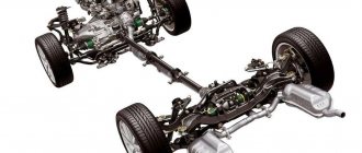
Chassis design features
The VAZ-2114 car is front-wheel drive. The power unit and gearbox are located in the engine compartment. Clutch drive is cable, mechanical. The gears in the box are controlled by a handle located in the cabin through a rocker mechanism.
Front suspension type: independent, telescopic. The front suspension struts are the main supporting elements in which the rotating elements are assembled. The strut assembly includes a spring that rests on the upper and lower support cups. The upper part of the rack is attached to the body with three bolts, and the lower part is attached to a brace, attached to the body spar by two brackets.
At the bottom of the strut, the bracket connects to the hub steering knuckle.
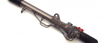
The wheel is turned by a steering rod connected to the steering rack. The rod turns the strut assembly, while at the top it turns on a support bearing, and at the bottom - on a ball joint. The anti-roll bar links the suspension on both sides and ensures its synchronous operation.
Block head and timing device
All front-wheel drive cars of the VAZ family, be it 2109, 2110 or 2114, have one cylinder head, common to all cylinders. They are mounted to the block using ten screws. During installation, a metal gasket is placed under it. This gasket is for single use and cannot be reused. There are five camshaft bearings at the top of the cylinder head.
The camshaft of the engine of the VAZ-2109 car has the index 21083. Some engines are equipped with 2110 or 2111 shafts; their design is slightly different from 21083, which allows for an increase in engine power. The shaft is cast from cast iron, there are five supports and eight cams on it that open the valves. It is driven by a toothed belt from the crankshaft pulley. The shafts can be correctly installed relative to each other using the alignment lug on the rear timing belt cover and the marks on the drive gears and flywheel.
Seats are pressed into the cylinder head, as well as valve guides. On the inside of the bushings there are grooves for supplying lubricant; the bushings are closed on top with oil deflector caps.
The valves are made of steel, and the intake head is made of heat-resistant steel. They are mounted obliquely in one row. The inlet valve has a larger diameter than the outlet valve. The gaps between the valves and camshaft cams are adjusted using shims that have increased wear resistance.
Pushers are metal cups moving in the cylinder head holes. To improve wear resistance, the surface in contact with the ends of the valve stems is cemented.
Pros and cons of the VAZ-2114
The period of the early 2000s was marked by the appearance of the VAZ-2114 on the market and during this period, approximately until 2006, it was considered prestigious to buy this car not only in Russia, but also in foreign countries. After six years and a massive influx of imported cars into the trade, the car that had taken the first step in the development of the domestic automobile industry began to be casually called a “scraper,” or even more roughly, a “pelvis.” The good news is that the percentage of such people is very small and the “hard worker” car continues to work to this day and helps out all segments of the population.
A huge plus about this car is that it can withstand all aggressive attacks both from its operation on poor-quality road surfaces and from natural conditions.
As with any machine, even a very expensive one, minor repairs are inevitable and maintenance is also necessary, but the price of these costs is offset by the honest return of all its energy. The VAZ-2114 car is reliable and there is nothing in its components that can break down critically; it can be repaired both in the city and in the wilderness, being far from super car services.
The machine is not complicated in design and is as simple and reliable as a coal-fired iron.
The last car, 2114, came off the assembly line, painted white, and the plant assemblers saw it off with tears in their eyes. It's sad, but it's a fact!
Body structure of Lada Samara 2114
The body of Samara is worth a closer look. It itself is all-metal, welded, load-bearing structure. Some body elements, for example, non-removable ones, are connected to each other by resistance welding, and in those places where access is partially limited - by semi-automatic electric welding in an inert gas environment. The manufacturer sealed body elements such as panel joints or welds with mastic. In general, the issue of protection (anti-corrosion) of the body of the Lada Samara 2114 should arise already when purchasing a car. Yes, the manufacturer provides underbody protection for a period of 5 years, but the car enthusiast should not forget that not all Lada parts are processed during assembly. In any case, there are places that are inaccessible for protection. Moisture, dust, dirt, snow and road treatment chemicals when they come into contact with metal have a detrimental effect on them.
Therefore, it is imperative to carry out anti-corrosion protection. It is worth noting that when selling a Samara 2114, the treated body is valued at much more expensive. Passive and active - these are two types of protection for the body of your car. Passive protects the metal surface from atmospheric influences, and active creates a thin anti-corrosion layer on the metal. Passive mastic is often used to preserve the bottom, wings, and sometimes shock absorber niches. It is worth noting that mastic should only be applied to a clean, dry surface in a thick layer before starting active driving.
Replacing the timing belt on a VAZ 2113-VAZ 2115
Removal
1) First, remove the plastic cover that covers the belt from dirt, various types of water and lubricants. The cover is removed as follows: take a wrench or socket wrench and unscrew the three bolts securing the cover (in the bottom photo the bolts are already unscrewed). Two bolts are present on the side and hold the cover in place, and one is located in the central part. By unscrewing them, you can remove the cover from the car engine.
2) Now turn off the power to the car by disconnecting the negative terminal from the battery. Then remove the alternator belt - read the article for details: “Replacing the alternator belt on a VAZ.” Set the piston of the fourth and first cylinders to TDC (top dead center). Simply put, place both pistons completely straight and without angles up. The publication will be useful to you: “Installing the piston of the fourth cylinder at TDC on a car.”
3) Then take a “13” wrench in your hands and use it to slightly loosen the nut securing the tension roller. Loosen until the roller begins to rotate. Then turn the roller by hand so that the belt loosens. Grasp the belt and carefully remove it from the rollers and pulleys. You need to start from the top, with the camshaft pulley. It will not be possible to remove all the pulleys, so only release the belt at the top.
4) Next, remove the front right wheel (removal instructions are available here: “Correct replacement of wheels on modern cars”). Now take a socket wrench or any other wrench that can unscrew the bolt securing the generator drive pulley (the pulley is indicated by the red arrow).
Note! The bolt is unscrewed with the help of a second person (assistant) and a mounting spatula (or a thick screwdriver with a straight blade). From the left side (in the direction of travel of the car) of the clutch housing, remove the plug marked in red. Then a spatula or screwdriver is inserted between the teeth of the flywheel (the teeth are indicated in blue) - the flywheel is kept from turning. You will have to use force, the main thing is not to overdo it. After unscrewing the bolt, remove the pulley and set it aside!
5) Now you will have excellent access to the crankshaft pulley and belt. At the last moment, the belt is removed from the lower pulley. It has now been completely removed.
Note! Although this does not apply to 8-valve cars of the Samara family, for general information we will explain: do not have the habit of turning the camshaft and crankshaft pulleys when the belt is not installed. Otherwise, you will mess up the valve timing (they are easy to adjust; you just need to align the flywheel and pulley to the marks). Turning the pulley, for example, on a 16-valve Priora, will cause the valve to meet the piston group and they may be slightly bent.
Installation
1. Carry out in the reverse order of removal, observing some nuances:
- firstly, we recommend that you clean the pulleys and tension roller from dirt and various types of grease that get on them over time;
- After cleaning, degrease the pulleys and tension roller using white spirit;
- start installation.
Install the belt first on the pulley from the bottom, moving to the top. As you put it on, it will sag, so pull it with your hands and make sure that it stands up straight and the pulleys are not distorted. After installation, make sure the marks match, then proceed to install the tension roller. Install the belt onto the tension roller (see photo 1), then climb down and reinstall the generator drive pulley. Be sure to ensure that the hole on the pulley, indicated by letter A, lines up with the mounting sleeve, indicated by letter B in the second photo. If you have a torque wrench (a very convenient thing that allows you to tighten bolts and nuts to a certain torque without overtightening them), tighten the bolt securing the generator drive pulley. The tightening torque is 99–110 N m (9.9–11.0 kgf m).
Next, proceed to adjusting the timing belt on the car: insert two drills or self-tapping screws into the two holes present on the tension roller (the holes are indicated by arrows in photo 1). In a good way, the adjustment is made with a special key. however, not everyone has one, so we are looking at an alternative method of tensioning. Insert two screws and insert a screwdriver between them (photo 3), then turn the roller counterclockwise. With the belt fully tensioned, tighten the nut securing the roller fully and fully (photo 3). Make sure that the steps have been carried out correctly: by hand, turn the belt exactly in the middle part between the pulleys with a force of 1.5-2 kg. If it turns approximately 90° (photo 4), then the belt is adjusted correctly. Otherwise, repeat the adjustment.
Note! An overtightened belt will lead to failure of the roller, belt and pump. A weak, under-tightened belt, while driving at high speeds, will jump off the pulley teeth and the adjustment of the gas distribution phases will be disrupted - the engine will not work properly.
2. Having installed the parts in place, be sure to check the alignment of the marks and check the belt tension.
