Principle of operation
The entire filling of the injection engine is electronic, there are many sensors. And if one fails, problems begin - the engine “troubles”, operates unstably, or even stalls completely.
Now briefly about how the injection engine control system works. First, the system needs to know what the temperature is in the manifold (intake) at a certain point in time. This is necessary to accurately calculate the mass of air located in the collector itself.
Secondly, do not forget that during each stroke of operation, air is sucked into the combustion chambers. Over the entire cycle, the engine consumes a certain amount of air - a volume equal to that of all four cylinders. So, everything is quite simple - there is data on the volume of the cylinders, the air density and temperature are known. There is only one thing left: to calculate the mass of air that enters each cylinder.
What is an absolute pressure sensor used for?
This device has two names, the first you already know, and the second - MAP sensor. But now let’s talk about why all those measurements that were described in the previous section are needed. It is worth mentioning that in injection injection systems, measuring the amount of air is carried out in too complex ways. Because there are no simple options for carrying out such measurements.
It is worth noting that only two device designs are used. There is an absolute pressure sensor (Lanos and domestic Priors work on them), there are also differential pressure sensors (on Japanese and American cars).
Why does the control unit need to know how much air the motor consumes? Everything is very simple - not pure gasoline is supplied to the combustion chambers, but mixed with air (proportion 14 to 1). Therefore, it is necessary not only to prepare such a mixture, but also to make the motor work ideally on it. The MAP sensor allows you to calculate the amount of air consumed and clearly formulate impulses to control the injection nozzles.
Measurement error
It is worth noting that the error is very high if the calculation is made using temperature and pressure. The fact is that depending on the technical condition of the cylinders and pistons, camshaft and valves, air consumption changes. It is for this reason that minor adjustments need to be made. But the absolute air pressure sensor will not be able to work independently. Oxygen sensors are installed in the exhaust manifold, which analyze the composition of the exhaust gases. Based on the data received from the lambda probes, the electronic control unit calculates the exact air consumption and makes the necessary adjustments.
S+S Regeltechnik product range
Constant work on improving the devices allows S+S Regeltechnik to present an extensive range of devices.
List of PREMASGARD absolute pressure transducers:
- Converters for gases and liquids;
- Converters for atmospheric air;
- Converters for air.
List of differential pressure switches and differential pressure monitoring relays PREMASREG:
- Air pressure switch.
List of devices for measuring volume flow PREMASGARD and PREMASREG:
- Measuring pressure transducer (volume flow);
- Volume flow measuring transducer / volume flow control relay.
Reliable, high-quality equipment from S+S Regeltechnik ensures control and stability of measurements. The presented pressure sensors are a reliable assistant for your enterprise.
Where is it installed
The MAP sensor is mounted exclusively on fuel-injected vehicles with internal combustion engines. There is a flexible pipe from the sensor fitting to the engine intake manifold. With its help, the sensor and motor are connected. Please note that the MAP sensor is always installed, even if there is no mass air flow sensor. Especially on cars that use a turbocharger. The sensor measures the excess pressure of the air, which is pumped by the compressor. The most common malfunction of the absolute pressure sensor will be discussed below.
Video on the topic
A large number of electronic devices are responsible for the full operation of injection engines, including the absolute air pressure sensor in the intake manifold. The device may not be a major one, but its unstable operation will definitely lead to either excessive fuel consumption or the complete inability of the vehicle to move. Based on this, knowledge about what an absolute pressure sensor is, what it is responsible for, what the symptoms of its breakdown are and how to eliminate them are simply necessary for a real car enthusiast.
Differential sensors
There are also differential sensors; the essence of their operation will be briefly described below. They are used to measure the amount of gas (air). The difference from the previous type is that the design has not one, but two fittings. The first is connected to the intake manifold, through which the pressure in the fuel system is measured. But the second fitting measures atmospheric air parameters. The difference of these two parameters is supplied to the electronic control unit. In addition, the sensors allow for better fuel combustion - part of the exhaust gases are returned to the intake system. Thanks to this, much less harmful compounds are released into the environment.
Types and verification
Please note that the manifold absolute pressure sensor can operate in different modes. Thus, some Ford cars use sensors that operate by changing the frequency of the generated voltage. Other types of devices use a method of comparing readings.
It is also worth noting that you can only verify that the sensor is faulty if you carry out complex diagnostics using an oscilloscope. It will be necessary to measure several parameters and analyze the quality and level of the output signal.
And now about what kind of breakdowns occur with such a device as an absolute pressure sensor. “Lanos” or domestic “ten” – it doesn’t matter, the symptoms of the malfunction are the same on all cars.
Motor tester-cylinder pressure sensor. Guide - part 1
To obtain an oscillogram of the pressure in the cylinder, it is necessary to warm up the engine to operating temperature, install a pressure sensor in the cylinder under study instead of an unscrewed spark plug, and install the high-voltage wire of this spark plug on a spark gap. In the case where the engine is equipped with a single ignition module for all cylinders (some Opel, Peugeot, Renault engines), you can remove the module and install additional high-voltage wires between its terminals and spark plugs, while observing safety precautions. If possible, disconnect the connector from the injector of the cylinder being diagnosed to prevent fuel supply. It is better to use external synchronization when taking an oscillogram, from the sensor of the first cylinder. Start the engine and take an oscillogram at idle speed.
IMPORTANT:
For a classic ignition system (coil with distributor), a gap of 5 mm on the spark gap (and a little more) will not affect the performance of the engine (except for a disconnected cylinder). But for the DIS ignition system, a gap on the spark gap of more than 5 mm can disable the cylinder paired with it (1 coil - 2 cylinders). In this case, in the best case, distortions will appear (for example) on the Px record (2 cylinders do not work instead of 1), and in the worst case, the ignition coil (or switch) may fail. The fact is that in the DIS system there is an idle and a working spark (depending on which cylinder has a compression phase or a bypass phase), with a large gap on the spark gap we create conditions when two working sparks actually occur (the total gap is too large), and there is a real chance disable the high-voltage engine system.
It is necessary to pay attention to the fact that the pressure reading at the moment of compression of the mixture differs from the values measured by a mechanical compressometer by approximately two times. If a mechanical compression gauge shows 12 atm, then this sensor will show a pressure of about 6 atm. Measurement with a mechanical compression meter takes place with the throttle valve fully open. And the graph shown corresponds to idle speed, when the throttle valve is almost closed and less air enters the cylinder. The maximum pressure reaches the values measured by a mechanical compression gauge at high speeds when the throttle valve opens. If you take measurements with a pressure sensor when cranking with the starter and with the throttle open, the readings will be the same.
And so We removed the signal.
4
Sensor failures
Much depends on what software (firmware) is used by the electronic control unit. If the manifold absolute pressure sensor fails, then the most favorable outcome is to switch the ECU to emergency mode. The engine begins to operate at average parameters, which, of course, cannot be called ideal. Gasoline consumption will be higher, and slight detonation may even occur.
But the saddest outcome is a complete disruption of operation, the inability to start the engine. It is worth noting that the absolute pressure sensor in the intake manifold is a very reliable device that rarely breaks down. Most often, the flexible hose that connects the fitting and the intake manifold is destroyed. There are two options: the tube either breaks or becomes clogged. In the first case, replacement will help, and in the second, you can simply clean it.
But if something happened to the filling of the sensor, you should not even try to repair it. The fact is that this device is very complex in its design, and interference will lead to destruction. It is much easier to purchase a new element and install it. However, in modern cars most of the devices are of a non-removable type, so if they fail, all that remains is to replace them completely.
Home Do it yourself Electrical equipment Malfunctions in the absolute pressure sensor: main symptoms Malfunctions in the absolute pressure sensor: main symptoms Absolute pressure sensor Many drivers have a problem such as too much fuel consumption. In search of the cause, you can disassemble and reassemble the entire car, but very often the culprit is a small-sized sensor of the electronic control system for the operation of a gasoline engine - the absolute pressure sensor. If it breaks down completely, which does not happen very often, the car may not start or drive at all. However, with partial malfunctions, the consequences can be very diverse, so increased fuel consumption is only one of them.
Why is a pressure sensor needed?
It is known that for normal engine operation it is necessary to prepare a high-quality combustible mixture - air and fuel in certain proportions. In carburetor engines, this problem was solved by jets in the carburetor body, their throughput regulated the proportions of air and gasoline, and the throttle valve dosed the supply of the finished mixture into the combustion chamber.
An injection engine allows for much wider use of the ability to adjust and more accurately maintain the proportions of the mixture, and changing them quickly, depending on the operating mode and needs of the engine. The fuel issue is clear; the injector and the entire fuel system can dose it quite accurately. To correct air flow in engines, an absolute pressure sensor is used, the signs of malfunction of which we will look at today, or an air flow sensor. Some motors may use both sensors.
Signs of sensor malfunction
- When cold the car starts up fine, but when hot it either needs to be revved up or it stalls immediately.
- The idle speed is in the range of 900 - 1100. In this case, the computer may try to normalize the speed to normal 750, the engine does not operate evenly
- Consumption increases
- Acceleration may occur with stuttering
If you notice one or more of the symptoms described above, we advise you to contact a specialist and have your car diagnosed.
Renault Logan, like any modern car, is equipped with a large number of different sensors to ensure the normal operation of the engine and all its components. Therefore, car owners from time to time have to deal with the failure of one or another regulator. Read more about how, pressure levels, lambda probe and other controllers on Renault Logan.
What types of pressure sensors are there?
Depending on the design of the engine, there may be two, three or more sensors that control the supply and air pressure into the system. For example, in engines with a turbine, another sensor may be installed that monitors the compressor pressure. In principle, the design of these devices is identical - they are designed to measure pressure and send data to the electronic engine control unit.
The sensor that interests us measures the so-called absolute pressure, that is, it shows the pressure value not relative to atmospheric pressure, but relative to complete vacuum. Depending on the principle of operation of the device, it can be designed according to two schemes: a device based on a thin film, which reacts to changes in pressure and generates a certain electrical potential transmitted to the ECU; a more accurate and modern sensor design system is micromechanical.
Features of air pressure and temperature sensors from S+S Regeltechnik
Using modern air pressure and temperature sensors from S+S Regeltechnik, you can monitor and control differential, elevated, absolute, relative and reduced air pressure. If necessary, the devices can also be used for other liquid or gaseous media. A progressive system using the piezoresistive measuring principle will allow you to guarantee extremely accurate data in the range from 50 Pa to 300 bar at temperatures from -40°C to +100°C.
The company's product range includes PREMASREG 1160 and PREMASGARD 1160 pressure sensors, capable of measuring excess pressure and displaying volume flow based on vacuum and differential pressure data. A comfortable and practical appearance is ensured by the patented S+S “Thor” design. It meets modern standards of strength and reliability, while ensuring the simplest possible installation process and further maintenance.
Operating principle and design of the device
The design of the device includes two chambers - vacuum and atmospheric. It is clear that the first chamber contains a vacuum, and the second chamber is directly connected to the intake manifold. In addition, the device body contains four strain gauges, which are attached to the diaphragm, and a silicon chip. Pressure acts on the diaphragm, and under its action it moves the sensitive elements, changing their resistance, as a result of which the silicon chip supplies a pulse of a certain value to the ECU. The strain gauges are connected in a bridge circuit to increase the impulse, and the voltage across the sensor can vary from one to five volts.
It is on the basis of the received voltage that the electronic control unit draws a conclusion about the pressure in the intake manifold. Higher pressure means higher voltage and vice versa. Depending on the design of the sensor, it can supply both an analog and digital signal, but for this it is necessary to integrate a special analog-to-digital signal converter circuit into the sensor body.
Intake manifold pressure sensor
The Manifold Air Pressure Sensor (MAP sensor) is one of the sensors used in the electronic control system of a gasoline engine. The data provided by the sensor serves to calculate air density and determine its mass flow, which in turn allows optimizing the processes of formation and combustion of the fuel-air mixture. The intake manifold pressure sensor acts as an alternative to the air mass meter. Some engine management system designs use an intake manifold pressure sensor in conjunction with an air flow meter.
In turbocharged gasoline engines, a charge pressure sensor is installed in addition to the pressure sensor in the intake manifold. The boost pressure sensor is installed between the turbocharger and the intake manifold and serves to regulate the boost pressure according to the needs of the engine. For example, a TSI twin-charger engine has as many as three pressure sensors: in the intake manifold, the charge sensor and in the intake manifold. The pressure sensors are identical in design. Turbocharged diesel engines only use a boost pressure sensor.
The intake manifold pressure sensor measures absolute pressure, i.e. air pressure in the manifold relative to vacuum. Therefore, another name for the sensor is an absolute pressure sensor.
Currently, two technologies are used for the production of sensors: micromechanical and thick film. Micromechanical technology is more progressive because provides higher measurement accuracy. Most modern pressure sensors are built using micromechanical technology.
The basis of a micromechanical pressure sensor is a measuring element, which consists of a silicon chip, a diaphragm and four strain gauges on it. The sensitive diaphragm of this sensor is manufactured using micromechanical technology. On one side of the diaphragm there is a chamber with a vacuum, on the other side the diaphragm is affected by air pressure in the intake manifold. Depending on the design of the sensor, pressure may be applied directly to the diaphragm or through a protective gel layer. The sensing element is placed in a housing, which, in addition to the pressure sensor, can also house an independent air temperature sensor.
Under pressure, the diaphragm bends. Due to mechanical stretching of the diaphragm, strain gauges change their resistance. This phenomenon is called the piezoresistive effect. The voltage changes in proportion to the resistance of the strain gauges. To increase sensitivity, the strain gauges are connected in a bridge circuit. An electrical circuit built into the chip amplifies the bridge voltage, which at the sensor output ranges from 1 to 5V. Based on the output voltage, the electronic control unit estimates the pressure in the intake manifold. The higher the voltage, the greater the air pressure.
When the engine is not running, the pressure in the intake manifold is equal to atmospheric pressure. When starting the engine, a vacuum (vacuum) is created in the intake manifold due to the closed throttle valve and the pumping movement of the pistons. When the engine is running with the throttle valve open, the pressure in the intake manifold is almost equal to atmospheric pressure.
The intake manifold pressure sensor can be analog or digital. An analog sensor produces an analog voltage signal. A digital sensor has additional circuitry that converts an analog signal to a digital signal.
In a thick-walled pressure sensor, the measuring element consists of a thick-walled diaphragm. There are four strain gauges located on the diaphragm, with the help of which the deformation of the diaphragm is assessed.
Symptoms of sensor failure
The not too intricate design of the sensor in new cars can be supplemented with a layer of special gel, which serves as a kind of protection for the sensitive element, which somewhat extends its service life. However, the sensor may fail, as indicated by the following symptoms:
- Gasoline consumption is increasing. This may be due to the fact that the sensor does not work at all or produces incorrect data from the ECU, which assumes that the pressure in the manifold is stable and continues to supply fuel in larger quantities than is actually necessary.
- The dynamics disappear against the backdrop of increasing consumption, and if acceleration does not improve after the engine has fully warmed up, most likely you need to go for diagnostics.
- Due to the constant overflow of gasoline in the throttle valve area, a persistent fuel smell may persist.
- Floating or uncontrolled idle speed.
- Dips in transition modes, when starting from a standstill, changing gears and changing the throttle.
How to check and replace DBP
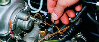
In order to find out where the sensor is located, you need to find a fitting on the intake manifold, from which a tube goes to the fitting of the sensor itself. By the way, the cause of the listed troubles can be a clogged or broken hose, and the device itself can be mounted either on the engine shield or on the wheel arch. Checking the functionality of the sensor is carried out only on special diagnostic equipment or using an oscilloscope.
The device cannot be disassembled and cannot be repaired. The price of a new sensor is within a thousand rubles, depending on the make of the car. When replacing the sensor, it is necessary to take into account that each modification of the device may have its own pinout, since it has three contacts - ground, signal and power, and the replacement process itself is simple and will take several minutes. Successful diagnosis and effective repair to all!
