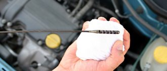
Car instructions are written to be followed. The fact that the value of optimal tire pressure is not only in the vehicle’s operating manual, but is also indicated on a plate attached to the driver’s door and duplicated on the gas tank hatch indicates the importance of monitoring this indicator.
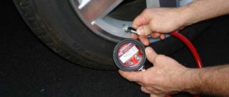
Checking the pressure twice a year when changing winter tires to summer tires is not the best option for car care. This should be done at least once a week, or better yet, daily before leaving the car; for this you will need a pressure gauge to measure the tire pressure.
Neglecting a simple procedure results in unpleasant consequences for both the car and the driver. What are the risks of driving a car with poorly inflated tires?
- Road grip deteriorates.
- For tires, lack of pressure is detrimental; they wear out faster, especially around the edges.
- Fuel consumption increases by 540 liters for every 20,000 kilometers traveled. For those drivers who spend a lot of time behind the wheel, additional refueling will not be cheap.
- The vehicle's stability decreases and it becomes more difficult to control.
- A wheel with a poorly inflated tire may spontaneously dismount.
- The braking distance increases.
And that is not all. A worn tire can burst if the car hits an obstacle, and this is already an emergency situation.
Things are no better if the tires are overinflated.
- The car is more difficult to drive.
- Driving with overinflated tires is uncomfortable.
- The suspension wears out faster.
- Lower grip.
Tire pressure needs to be monitored.
Regulations for checking pressure gauges: terms and conditions
Checking the readings of working instruments with their subsequent sealing, in accordance with the current GOST, is carried out at least once a year. In addition, the enterprise must carry out a scheduled inspection with a control pressure gauge at least once every six months. Each such check must be accompanied by a corresponding journal entry.
If the necessary control device is not available, you can check it with a sealed working pressure gauge. The main thing is that its scale and accuracy class coincide with the pressure gauge being tested.
The technical condition of tires and wheels is checked in the specified order
- Inspect the vehicle's wheels. Assess the compliance of the disks and methods of their fastening with the vehicle structure. If it is necessary to provide access to the wheel fastening elements, remove the decorative protective caps of the disks. When installing disks on a vehicle that are not provided for in the manufacturer’s documentation, make sure that the outer edge of the disk does not protrude beyond the dimensions of the vehicle, as well as that the inner edge of the disk does not touch the elements of the braking system, steering and suspension at maximum steering angles. Visually check the reliability of the wheels and the presence of all fasteners. Inspect the disks and rims of the wheels for damage, cracks, or incorrect installation of the locking rings.
- Inspect the vehicle tires. Based on their markings, determine the compliance of the installation of tires on the axles of the vehicle, the size and design of the tires with the documentation of the vehicle manufacturer. When installing tires not specified in the documentation, make sure that the sidewalls of the tires located on the outside do not protrude beyond the dimensions of the vehicle, and that there is no contact with parts of the tires located on the inside, elements of the braking system, steering and suspension at maximum steering angles. , as well as the treadmills touching the tires of the body elements, chassis and tail at maximum upward travel of the suspension. Make sure there is no damage to the tires, exposing the cord, or any tread separation. If the vehicle has studded tires, check the presence of such tires on all axles and on the spare wheel, as well as the installation of the “Studded” identification sign.
- Check tire pressure. The check is carried out using a tire pressure gauge that corresponds in its measurement range to the maximum pressure indicated on the tire. If the maximum tire pressure is specified in psi, you must convert its value to kilopascals (1 psi = 6.895 kPa). The value of the measured tire pressure must not exceed the maximum permissible indicated on the tire and must correspond to the standard values specified in the vehicle’s operational documentation.
- Determine the amount of tire tread wear. The maximum tread wear is considered to be such wear at which the residual height of the tread protrusions has a minimum permissible value on an area whose width is equal to half the width of the tread tread, and the length is 1/6 of the tire circumference in the middle of the tread or (in case of uneven wear) on the total area the same size. The length l of the zone should be no more than 1/6 of the circumference.
The width of the zone b2 is greater than or equal to 0.5b1.
The remaining tread height should not be measured at the locations of the ledges at the base of the tread pattern elements and half-bridges in the area where the grooves intersect.
For tires that have a solid rib in the center of the treadmill, the tread pattern height is measured along the edges of this rib, for all-terrain tires - between the lugs in the center or in places least distant from the center of the treadmill, but not along the ledges at the base of the lugs and not along half-bridges.
The remaining tread depth can be measured with a depth gauge equipped with a caliper, as well as with a special template - a tread depth gauge.
On tires with wear indicators, the maximum permissible tread depth is determined by the appearance of the indicators.
A wear indicator is a design element of a tire's tread that indicates the limiting condition of its tread in terms of tread wear. Wear indicators are usually located in the transverse plane of the treadmill in six radial sections. The locations of the indicators are indicated on the sidewall with various icons, mainly the abbreviation TWI (Tread Wear Indicator).
How to check a gas pressure gauge
In general, the test consists only of comparing the data of the pressure gauge being tested with the readings of the control device or calculating the current gas pressure, then measuring it using a pressure gauge and comparing the data. To do this, you only need a control pressure gauge and a thermometer. If we describe this procedure in more detail, it looks like this:
- install the pressure gauge sensor into the container through a special fitting;
- when the pressure value is recorded, remove the pressure gauge and install a control device in its place;
- After comparing the readings of the two instruments, check the accuracy of the instrument readings;
- if the instrument readings do not coincide with the reference pressure gauge, it is necessary to adjust it so that under the same operating conditions the instruments show the same pressure values;
- there are adjusting bolts on the pressure gauge body, with the help of which adjustments need to be made;
- with an electronic analogue the actions are the same, only you need to take into account that this device has inertia, so the readings must be held for 8 to 10 s.
If there is no reference device, you must first calculate the working pressure using the formula P2=T2•P1/T1:
- this will require a vessel of a volume that is known or can be measured, containing air at normal atmospheric pressure and room temperature;
- the vessel is hermetically sealed and gradually heated;
- then the pressure inside the vessel is simply calculated using the formula, where T1 and T2 are the initial and final air temperatures in the vessel, and P1 is the atmospheric pressure.
- if the instrument readings do not coincide with the calculation, then it is necessary to adjust it to the data obtained during the calculation.
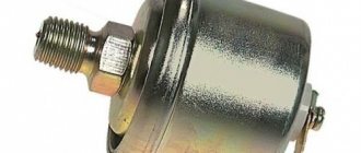
A pressure gauge is a device whose purpose is to measure pressure levels. And the need to measure a motorist’s pressure may arise in different cases. You can find out more about how car pressure gauges are checked at home and what requirements apply to these devices below.
Digital pressure gauges
These devices have more functions and are more convenient to use.
Wester MTG-100 – with built-in hammer and seat belt cutter
Wester MTG-100 determines tire pressure with high accuracy: error - 0.06 ATM. The measuring range is from 0.21 to 6.9 bar - sufficient for a car or small truck.
All received information is displayed on a digital indicator. The car pressure gauge is powered by two AG8 batteries. The built-in flashlight requires AAA batteries.
Advantages:
- reliable and accurate work;
- compactness and light weight;
- built-in hammer;
- low price.
Flaws:
- small digital display screen.
Pressure gauge with good price/quality ratio.
Daewoo DWM7 – with shockproof housing
The Daewoo DWM7 pressure gauge was assembled in Korea, so there is no need to worry about the build quality. Ergonomic bright body - rubberized. It is comfortable to hold in your hands - it does not slip and does not break if dropped. If gasoline or oil gets on the body, nothing will happen to it.
The maximum pressure that the pressure gauge can measure is 6.9 ATM. The result is displayed on the backlit display. If there is not enough light, a built-in LED flashlight is available to the car enthusiast. The Daewoo DWM7 requires 4 LR44 batteries to power it.
Advantages:
- 4 measurement systems;
- attractive appearance;
- weight – 56 g;
- small error in air pressure measurement.
Flaws:
- Batteries run out quickly, especially in cold weather.
A good pressure gauge with a low price.
Jock M10 – with three measurement scales
The M10 pump is assembled in China, but the quality of the device does not suffer from this. The tire pressure gauge measures tire pressure in three units of measurement. In bars, its operating range is 0.15-7. Suitable for both trucks and cars.
The LED display on which the information is displayed is backlit, so you can measure pressure even in the dark. The round-shaped case made of black plastic has a light weight - 70 g. The pressure gauge is powered by three LR44 batteries.
Advantages:
- easy to use;
- economically consumes battery energy - automatically turns off 1.5 minutes after measurement;
- built-in flashlight in the elongated part of the body.
Flaws:
- does not work at temperatures below 0 degrees.
A good pressure gauge model for warm regions.
Requirements for pressure gauges
First, let's look at the requirements for pressure gauges according to GOST:
- Installation of the device in accordance with GOST can be carried out on the vessel fitting up to the shut-off valves.
- The main requirement according to GOST, which must be presented, concerns such a nuance as the error of the pressure gauge. The accuracy class must be at least 2.5 if the operating pressure level is below 25 kg/cm2. If the pressure is higher, then the accuracy class should be equal to 1.5.
- Any device according to GOST is equipped with a scale so that the measurement limit of the required parameter is located in the second third of the scale.
Checking pressure gauges
Verification - determining the errors of a measuring instrument and establishing its suitability for measurement. If the error of a measuring instrument is higher than permissible, it is unsuitable for further measurements. When calibrating pressure gauges, reference instruments provide initial readings with which the readings of the instruments being verified are compared, i.e., a direct comparison of the instrument being verified is made with the reference instrument. The three most common types of reference gauges are: U-tube gauges, deadweight gauges, and gauge strain gauges.
Using a U-shaped pressure gauge for verification
U-tube pressure gauges are simple, accurate instruments for measuring pressure. The measured pressure value in a U-shaped pressure gauge is balanced and determined by a column of working fluid equal to the sum of the columns in both bends of the tube. The most common liquids used in pressure gauges are water, mercury and instrument oil. The range of pressures measured by a pressure gauge is determined by two factors: the height of the pressure gauge tube and the type of fluid in the tube. Differences in liquid weight result from differences in the pressure created by each liquid. The pressure measurement result is usually expressed in millimeters of water or mercury.
Verification rig with U-shaped pressure gauge
1 - calibrated device, 2 - U-shaped pressure gauge, 3 - flexible tube; 4 - tee A flexible tube and tee are used to connect the pressure gauge to the device being tested and the pressure source, which in the example shown above represents the instrumentation compressed air system. The instrument air pressure regulator regulates the pressure applied during the calibration process. Since the tube attached to the air regulator is connected to the U-shaped pressure gauge and to the instrument, the same pressure is applied to both instruments.
Using a deadweight pressure gauge for checking
Deadweight pressure gauges are exemplary instruments that are used to measure pressure expressed in basic units: force and area. The formula used to determine pressure (pressure = force/area) is actually a description of the operating principles of a deadweight tester. The force in deadweight testers is provided by weights in the form of metal disks. The area is the area of the piston. The principle of operation of deadweight piston pressure gauges is based on balancing the force developed by the measured pressure on the piston with the force of gravity of the load loading the piston.
A deadweight tester can be used in testing installations as a reference measuring instrument and as a source of pressure. In addition to providing accurate pressure readings, deadweight testers also create or increase pressure using a press, which is part of the deadweight tester design.
Basic elements of a standard deadweight tester
The figure above shows the main elements of a standard deadweight tester. They include the hydraulic press, the hydraulic press handle, the fluid reservoir, the pipe, and the cylinder body, which contains the piston and cylinder. A weight tube holder is attached to the piston, which serves as a support for the weight tube. The picture also shows a set of disks of different sizes. Verification installation with deadweight piston pressure gauge.
The reservoir contains a liquid, which is based on either oil or water. In most cases, the type of fluid used in a pressure gauge is indicated either on the gauge body or in the instrument manual provided by the manufacturer. The press is used to pump liquid into the cylinder.
The movable piston is located in the cylinder. Liquid is pumped into the cylinder until the piston hangs. Pistons are labeled according to their surface area. Deadweight testers are often supplied with multiple pistons. Changing the pistons allows the device to be used for a wider pressure range. The weight tube holder is attached to the top of the piston. The weight tube sits on a holder. The tube is hollow, open at one end. At the lower end of the tube there is a flange on which the disks rest.
With the help of disks, a known force, determined by the mass of the disks, is imparted to the deadweight pressure gauge, to which the device being verified is connected. Each disk has its mass indicated. The engraving on the body indicates the pressure achieved by the disk or disks representing a given mass and the piston of a given area.
The pipe is part of the deadweight pressure gauge to which the device being tested is connected. This connection allows the pressure created in the reference device to be applied to the device being tested.
When using a deadweight pressure gauge as a reference instrument, the device under test is connected to the pressure gauge connection, and the pressure to be generated is determined from the diagram on the pressure gauge body. To obtain the required pressure, the desired piston or disc(s) is selected. Once the piston is installed, the weight tube is installed on the holder and then the discs are added.
Verification installation with a deadweight pressure gauge 1 - device to be calibrated, 2 - pipe, 3 - load tube, 4 - removable disks (weights)
Deadweight testers are typically used to measure pressures above 15 psi. Pressure in a deadweight tester is created using a hydraulic press, which increases the amount of fluid in the pressure gauge body. This fluid holds both the piston and the discs. The discs and piston remain in place as long as the pressure exerted on the fluid in the gauge body is less than the force exerted by the discs on the weight tube. But as soon as the fluid pressure becomes equal to the force exerted by the stacked disks, the piston and disks rise and freeze. At this point, the pressure indicated by the instrument under test is compared with the deadweight gauge reading, which represents the total force exerted by the disks and deadweight holder on the piston. For example, if two discs representing 5 and 20 psi were installed on the piston, the deadweight gauge would read 25 psi plus another 5 psi when taking into account the piston and tube holder, i.e. 30 psi. Each piston and holder has its own mass, indicated in the weight plate on the device body.
Using a standard deformation pressure gauge for verification
The principle of operation of exemplary deformation pressure gauges and pressure-vacuum gauges is similar to working pressure gauges and vacuum gauges. A distinctive element of the design of exemplary devices is the zero corrector and arrester. They are very sensitive, high-precision instruments, specially designed for checking working pressure gauges. Strain gauges differ from U-tube gauges and deadweight gauges in that they must be periodically calibrated to maintain their accuracy. Deadweight piston pressure gauges are usually used to verify standard deformation pressure gauges. The process of calibrating a standard deformation pressure gauge is essentially similar to the process of calibrating any pressure gauge.
Verification installation with an exemplary deformation pressure gauge 1 - calibrated device; 2- instrument air pressure set point; 3 - standard pressure gauge
The reference pressure gauge and the device being tested are connected to the same instrument air pressure set-point so that the same pressure is applied to each device. As a result of calibration, the readings of the working instrument must coincide with the readings of the reference pressure gauge at each point on the instrument scale.
Verification installation with a standard deformation pressure gauge and a deadweight pressure gauge as a pressure source 1 - standard pressure gauge; 2 - device to be checked
In a testing installation with a standard deformation pressure gauge, in which the pressure source is a deadweight pressure gauge, the reference pressure gauge and the device being verified are connected to the connection of the deadweight pressure gauge in order to ensure that the same pressure is applied to each device. In this case, the deadweight gauge functions as a pressure press rather than as a working standard. A reference pressure gauge provides known input values with which the readings of the device being tested are compared.
Portable testing unit 1 - standard deformation pressure gauge, 2 - air pressure regulators, 3 - manifold with fittings
Calibration can be carried out in production conditions or in the instrumentation workshop. A portable pneumatic calibration machine, such as the one shown in the figure above, can be used to calibrate instruments on site. In addition to the portable testing unit itself, the portable set also includes pressure regulators and a manifold with fittings to which the device being tested is connected. A regulated air source is connected locally to a portable, portable verification unit to create the pressure necessary to perform the verification.
Calibration Features
Next, we invite you to learn about calibrating the device.
The device calibration procedure itself can generally be divided into several main steps:
- Diagnostics of parameters, which we will discuss below, using a known standard or input data.
- The next step will be to adjust the device until the obtained indicators become equal or proportional in accordance with the existing input data.
As for calibration itself, this procedure includes many checks and adjustments. When the device is fully calibrated, this will mean that it will be able to obtain the most accurate values of the parameters that you measure.
Now let's briefly talk about the equipment that may be needed for calibration. The basic equipment that will be required should include a so-called reference device, a source of operating pressure that can be adjusted as needed. You will also need elements to connect the device to a pressure source and a reference device and several tools that will be useful for adjusting the device. The purpose of measuring devices is to transfer the sizes of physical units from standards to working devices.
As for working measuring instruments (measuring devices), their purpose is to carry out measurements in industry. According to their accuracy class, they can be divided into technical and laboratory. Since not every car enthusiast has such devices, taking measurements can be problematic.
How to check using the flow method?
You can make calculations using tables of values, but the result will not be accurate.
Therefore, the best option would be to carry out calculations on site, taking into account the speed of water flows, the material of the system pipeline, and other properties of the pipeline.
The simplest formula for calculating the fluid consumed will be:
Q=П*d^2/4*v , where:
- Q is the water flow rate we are interested in (liters per second).
- v —flow velocity (m/s).
- d – pipe diameter (in cm).
- P - "Pi number" - a constant from mathematics, approximately 3.14.
For example, there is: d=4, v=2. In this case: Q=3.14*4^2/4*2=3.14*8=25 liters per second.
This formula can be used when searching for other unknowns. In the case when the diameter along with the water flow rate is known, its speed can be determined. Or, if the speed is known and the flow rate is known, the diameter can be calculated.
All about verification
Now let's talk about how pressure gauges are checked, the timing and frequency of the devices being checked, and what rules should be followed.
If calibration of pressure gauges is carried out in laboratory conditions, then according to the rules it includes the following steps:
- visual diagnostics;
- setting the scale needle to the zero mark;
- diagnostics of the position of the arrow on this mark;
- The verification methodology includes identifying the main error.
Frequency and timing
As for frequency, at enterprises it is usually entered into the appropriate audit log. But since ordinary car enthusiasts usually do not keep a log of control checks of pressure gauges, this information can be recorded separately in a notebook. The frequency of diagnostics may vary depending on the device manufacturer; according to the rules, on average it can range from 12 to 60 months (the author of the video is the Avtozvuk.ua channel - Avtozvuk Database).
Why check tire pressure?
As I already said, the correct pressure in the tires of a car means good grip of the tires on the road, and good grip on the road means the safety of the driver and his passengers. As a rule, or most often, drivers do not pay attention to tire pressure, determining it “by eye”. But as statistics show, many pay a high price for such a careless attitude... By the way, not only safety, but also fuel consumption, as well as tire wear and service life depend on tire pressure, although if safety is not an argument, then it is unlikely fuel consumption and tire wear will force someone to monitor the tire pressure.
Insufficient tire pressure will lead to poor handling and will also increase braking distance. It’s also not good to overinflate the wheels; although this improves handling, it increases the braking distance and seriously damages the suspension. You will feel all the holes and bumps in the cabin. The correct pressure is indicated by the manufacturer in certain places (glove compartment, doorway, gas tank cap, etc.), most often for passenger cars the correct pressure is considered to be 2.0-2.2 atmospheres.
Types of modern DBP
DBPs differ in the type of output signal and purpose (applicability).
Based on the type of output signal, devices are divided into two groups:
In the first case, the sensor generates an analog signal (it is taken directly from the strain gauges), which is sent to the electronic unit, where it is processed. These are the simplest sensors in design, which are practically not used in new cars, since only certain electronic engine control units are suitable for working with them.
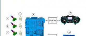
Design of an absolute air pressure sensor with integrated evaluation circuit
In the second case, an evaluation circuit is integrated into the sensor itself, which measures and converts the analog signal from the piezoresistors into digital form - this signal is sent to the electronic unit. The basis of this type of DBP is made up of special microcircuits that contain both a sensor element and an evaluation circuit. This type of sensor is most often installed on new cars, since it is suitable for most controllers with the appropriate input.
A separate group consists of the so-called T-MAP sensors - integrated temperature and DBP sensors. In addition to the MEMS sensor, they contain a temperature sensor based on a conventional thermistor; such a device measures pressure and temperature, which makes it possible to more accurately determine the amount of air entering the cylinders and make adjustments to the operation of many auxiliary systems (including the intercooler for engines equipped with a turbocharger, and others).
Based on applicability, DBPs are divided into two large groups:
- For atmospheric engines - measure pressure within 0-1 atmosphere;
- For turbocharged engines, pressure is measured in the range of 0-2 atmospheres or more.
There are also sensors for measuring pressures up to 5-6 atmospheres; they are most often used not in the intake manifold (since such pressure is rare in engines), but in the pneumatic system of cars.
The sensors are also available for supply voltages of 12 and 24 V, and for their connection various types of electrical connectors can be used (usually with blade contacts for individual connectors or group blocks, but there are also options for pin blocks).
Low pressure
DIY low pressure tires
1. Increased side wear
wheel faults, deformation of the tread sole inward.
2. Increased fuel consumption due to increased rolling resistance.
3. Increased wear of suspension parts due to increased torsional loads.
4. Increased load on the gearbox and drives.
5. Deterioration in car handling due to the tendency for the tire to deform (tendency for the car to “steer”, “yaw”, etc.).
6. Increased braking distance due to decreased traction with the road or loss of vehicle control when braking.
7. Increased risk of valve damage due to “rotating” the disk on a weak tire (for tube tires).
8. Increased risk of the wheel “dismounting” under strong lateral loads, with a corresponding loss of vehicle control.
9. Increased risk of aquaplaning.
High pressure
1. Increased wear in the center of the tread sole.
2. Increased load on the suspension and car body due to increased rebound characteristics of the wheel - the ball effect. The ride is not very comfortable due to the fact that the wheel “catches” every pebble or hole.
3. Deterioration of vehicle controllability due to a decrease in the contact area with the road surface.
4. Increased braking distance and tendency to skid by reducing the contact area with the road surface.
5. Increased risk of puncture or damage, as well as “explosion” of the wheel.
Types of pressure gauges, their pros and cons
Pressure gauges for measuring tire pressure differ in their operating principle. There are two main types, which have their own advantages and disadvantages:
Mechanical devices
This is the older generation, gradually being replaced by modern electronic innovations. Their operation is based on the action of air on a coordinated system of rods, gears and springs. The readings are displayed on a special scale. This group of devices includes pointer and rack-and-pinion pressure gauges.
Pointer - gear type with a scale and arrow. Some models are equipped with a valve to release excess air, which increases their convenience. When choosing a pointer pressure gauge, you need to pay attention to the accuracy class of the device indicated in the passport. The higher it is, the smaller the measurement error.
Switch
Rack and pinion
The main advantages of devices of this type are:
- accessibility and ease of use;
- relatively low price;
- reliable operation;
- good accuracy of readings.
The disadvantages include the following:
- limited maximum readings;
- increase in measurement error when approaching the maximum values for the model;
- sensitivity to dampness and temperature;
- the need to double-check the results.
Electronic devices
An electronic pressure gauge for measuring tire pressure differs from mechanical analogues in the greater accuracy of the readings given. These devices are equipped with a liquid crystal display from which measurement results can be easily read. Many modern devices additionally have the ability to measure wheel temperature.
Read more: Throttle body 405 engine
The advantages of this class of devices include the following:
- high measurement accuracy;
- compactness, convenience and lightness of the device itself;
- equipped with additional functions (display backlight, flashlight, tread depth measurement, several units of measurement).
Digital pressure gauges for measuring tire pressure also have a number of disadvantages:
- high price;
- the need to monitor the battery charge;
- in the cold, the performance of the LCD screen deteriorates;
- at air temperatures below zero, the error increases.
Pressure control systems
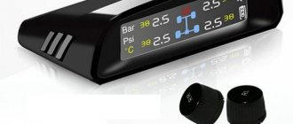
An alternative to traditional pressure gauges are modern devices and systems for monitoring tire pressure. These include:
Electronic sensors with radio transmission. They are installed on a nipple and display readings on the on-board computer using a radio signal. They are very easy to use, have high accuracy, control the temperature of the wheels and correlate pressure indicators with it, giving visual and audio signals. However, expensive and subject to risks of theft and vandalism
Indicator caps. Installed on nipples, information is provided visually using multi-colored retractable disks. Convenient, accurate, but not protected from vandals
Additional software extension for the ABS system. Controls the dependence of the radius of the wheels on the air pressure in them. Information about discrepancies between parameters and acceptable values is displayed and an audible signal sounds.
How is blood pressure measured?
Relationships between the most popular pressure units:
- 1 bar = 0.98692 atm = 1.0197 atm (kgf/cm²) = 10 5 Pa = 14.504 psi;
- 1 atm = 1 kgf/cm² = 0.96784 atm = 0.980665 bar = 14.223 psi;
- 1 atm = 1.01325 bar = 1.033 atm = 14.696 psi.
Even our small sample demonstrated that each manufacturer measures pressure differently. For example, the reference pressure gauge is marked in bars, the IMG Steel Tire Gauge V720 device (No. 10) is marked in kg/cm² and psi, Autostop (No. 1) prefers atmospheres (atm - physical atmosphere), and the creators of the Heyner AeroStop device (No. 9) They clearly believe that kg/cm² and bar are the same thing, and therefore one scale for two is enough for them.
- Advice:
take the time to clarify what the pressure in the tires of your car should be, without confusing bars with atmospheres. Then, once you select the appropriate pressure gauge, make sure you interpret its readings correctly. It’s easier to communicate on this topic with electronic products: they usually quickly jump from one system of units to another - just press a button.
Contents
Tips for choosing a tire pressure measuring device
What should you look for when buying a pressure gauge? Which pressure gauge is best for measuring tire pressure? It all depends on personal preferences, driving experience and use of devices that measure tire pressure, and the amount you are willing to spend on the purchase. You can choose the optimal device for yourself if you follow a certain plan:
- Decide what type of device you need - mechanical or electronic. Many motorists, given the reduced accuracy of electronic pressure gauge readings at sub-zero temperatures, prefer to have both types of devices in their car.
- Units of measurement also play a role in ease of use. Here again, electronic devices have the upper hand, being able to change units at the simple press of a button.
- Select the accuracy class of the device. Pressure gauges of class 1 have the least accuracy (1-0.5), class 2 is medium (0.50-0.1), class 3 is the most accurate (0.02-0.05).
- Pay attention to the strength of the case, compactness, ease of reading, the presence of an excess air release valve and other additional functions. Typically, electronic devices are inferior in strength to their analogues.
Each type of pressure gauge has its own strengths and weaknesses. When choosing, take into account the desired measurement accuracy, the units in which the manufacturer of your car indicated the pressure standards in the reference table, as well as the features of your vehicle.
For example, for bicycles, especially for road ones, devices with large maximum readings are needed. Passenger car owners are more free to choose. A pressure gauge for measuring pressure in truck tires must be reliable and have high strength characteristics.
A pressure gauge is a device for determining tire pressure (readings in atmospheres). It is widely used by motorists (motorcyclists) when operating vehicles, because pressure deviations from the norm are fraught with various consequences for both the car and those sitting in it. Therefore, it is important to know how to choose the right tire pressure gauge. After all, each of them has its own characteristics, advantages and disadvantages.
Pressure gauges are divided into three types:
- Mechanical (analog). The device is distinguished by its extreme simplicity of design, reliability and convenience. The dial has a scale indicating pressure in real time. Pros:
- low cost of the device;
- accuracy of readings;
- readings are fast.
- the device is sensitive to moisture and cold;
- Rack and pinion.
Less common compared to the previous device. The appearance is similar to the rod (stand). The principle of operation is simple - the spring compresses under pressure, thereby taking measurements. Pros: Read more: What kind of carburetor for Niva 2121 - relative reliability;
- affordable price.
- The device is easy to break.
- poor adaptation to sub-zero temperatures, which reduces the accuracy of pressure measurement;
- high price.