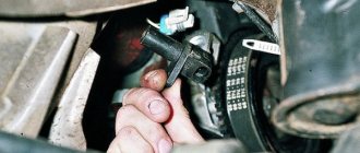
Car diagnostics can be carried out in almost every car service center; the only question remains about the quality of the diagnostics performed. Every day the world of automobile manufacturers is developing at an accelerated pace, new technologies, ideas, materials are appearing, the model range is expanding and new functions appear for comfortable driving. All these innovations also require maintenance and high-quality diagnostic equipment. In this regard, the capabilities of car services and equipment for car diagnostics are also expanding. A modern car service center must keep up with the times and modernize its work and equipment to provide quality car repair and diagnostic services.
One of the most dynamically developing sectors of the automotive industry is the development of new engines and their control systems. Speed, throttle response, efficiency, ease of control - all these qualities of modern engines equipped with the latest control systems can evoke only the most positive emotions in the motorist. But over time, owners are faced with the problem of maintaining such devices, and here one can only complain that they have not yet come up with an engine that does not require maintenance at all.
Manufacturers are also trying to simplify the maintenance system as much as possible; the procedure for changing oils and filters has been greatly simplified, but the main difficulties arise when failures occur in the engine control system and the old proven methods no longer work in modern cars.
In order to plug this gap in automotive service, a new specialty has appeared at car services - diagnostics of engine control systems. With the advent of this specialty, which motorists and carburetor specialists began to actively study, the heads of car service centers faced the urgent question of equipping workplaces for diagnosing injection engines. If car services as part of large companies that have dealer agreements with various manufacturers can pre-train their personnel in factory training centers, then small car services are often forced to start this business from scratch.
Firstly, all equipment for diagnosing car engines can be divided into several groups, each of which performs its own range of tasks.
- Engine control unit scanners
This group of diagnostic equipment is a set of devices designed to establish communication with vehicle control units, read and erase errors, read current values of sensors and internal parameters of the control system, check the functionality of actuators, adapt the control system when replacing individual vehicle components or during major overhauls. engine repair.
According to the majority of car services involved in car diagnostics, it is not advisable to purchase various professional diagnostic scanners, so usually the services have several semi-professional but universal scanners for diagnosing cars of various brands with a fairly wide range of data assessment capabilities, and the lack of information through these scanners is compensated by the use of other equipment for car diagnostics.
- Measuring instruments
This group of equipment compensates for the functional shortcomings of diagnostic scanners and rechecks their operation to obtain more accurate indicators of on-board computer sensors
- Testers for actuators and engine components
To obtain more accurate data when diagnosing a car, in addition to the listed equipment, car services also use specialized devices. Let's talk about the main ones.
Pressure meters
In this group of devices, one representative of which - the compression gauge - has long been loved by all car services, there is a significant addition. First of all, this is a fuel pressure tester, which was not available in car service centers designed to repair carburetor cars.
Also gaining great popularity is a valve-piston group leak tester, which makes it possible to more accurately determine the location and nature of a leak in the combustion chamber, compared to a compressometer, a vacuum gauge, which allows one to evaluate the correct operation of the engine intake system, and a catalyst backpressure tester, which allows one to evaluate the throughput of the catalyst.
Specialized car testers. When repairing contact ignition systems, a specialized automotive tester was often sufficient to find faults in the system. Given the predominance of electronic ignition systems, its capabilities for diagnosing them are clearly insufficient; automotive oscilloscopes and motor testers, which have much greater capabilities in comparison, come to the fore.
Proposals from professionals
If you don’t know where to get engine diagnostics done efficiently, quickly and at an affordable cost, then contact Vostok Auto. We have extensive experience in servicing cars of all famous and forgotten brands.
- Vostok Auto has been working in the car service market for many years and is one of the pioneers in this area in Moscow.
- Our team includes only professionals in their field - an experienced diagnostic electrician, a diagnostic engineer with higher education and a teacher-professor at MADI. Each of them knows the car from the “bones” to the last wiring, understands the processes occurring in the engine, which is very important for the correct choice of method of “treating” the car.
- Our technicians get to the bottom of the problem and give life to even the most hopeless machines with complex faults.
- Engine diagnostics, the price of which is not inflated depending on the cost of the car, is carried out using high-precision equipment, followed by “treatment” of the system.
- Modern diagnostic equipment: scanners, motor testers, smoke machines, oscilloscopes - we have it all in our arsenal.
Strobes
Although installing the ignition in most injection engines is not possible, test values for ignition systems still exist, and timely determination of the discrepancy between the calculated and actual ignition timing angles often helps determine the nature of the malfunction when diagnosing a car. But to check the ignition timing in injection engines, it is necessary to use stroboscopes equipped with flash delay adjustment, since these engines usually do not have a separate mark for setting the ignition timing.
Computer engine diagnostics and its necessity
There can be many reasons for inspecting a car, and a full diagnosis of an injection engine should affect all interconnected systems. It is this approach that allows you to correctly determine the “sore” point and identify faults in each block separately.
Engine diagnostics is necessary in the following situations:
- After purchasing a used vehicle, since new units come with a warranty from the manufacturer.
- Before going on a trip.
- Also if there is excessive noise, engine malfunction or strange behavior of the car.
High voltage arrester
This diagnostic equipment allows you to check the operation of the vehicle's ignition system under a load close to the real one.
All these devices can be used as equipment for diagnosing cars of various types and models, but in any case, the most important tool is a live car service specialist who, based on experience, is able to correctly analyze the information received and evaluate the instrument readings to draw conclusions about car diagnostics and identify causes. malfunctions. Take care of your cars and diagnostics will bring only positive news!
Superficial inspection of the internal combustion engine, measuring compression and fuel pressure
So, before starting work, you should carefully inspect the engine and engine compartment. Wiring elements, fuel hoses, pipes, etc. deserve special attention.
Then you need to check the condition of the air filter, as well as the fuel filter. If the filters are clogged, then this may cause the unit to malfunction. At the same time, the level of technical fluids (engine oil, antifreeze, antifreeze, brake fluid, etc.) is checked.
Next, you need to warm up the engine to operating temperatures. Then you should let off the gas. If gray, gray, blue or white smoke is visible from the exhaust pipe, then this may indicate various problems (impaired mixture formation, problems with the combustion of the fuel charge, coolant or engine oil getting into the combustion chamber, etc.).
Experienced specialists always check the crankcase ventilation system. For a quick on-site check, simply disconnect the crankcase ventilation system pipe and then insert a small piece of clean cloth into the pipe. Then the engine is started and accelerated.
If oil flies from the pipe or smoke is clearly coming out, then this may indicate problems with the piston rings or a problem with the ventilation system itself. Also, as part of diagnostic procedures, it is necessary to measure compression and fuel pressure.
To measure compression, you will need to unscrew the spark plugs on gasoline engines or the glow plugs on diesel engines. At the same time, a visual inspection of the candles themselves is also carried out. If the compression is below the permissible norm, then there is a high probability of CPG wear, valve burnout, stuck rings, etc.
As for the power system, then on many gasoline units you can measure the fuel pressure in the fuel rail. This measurement allows you to determine fuel pump malfunctions, clogging of fuel filters, and breakdowns of the pressure regulator.
Troubleshooting in an injection engine.
The start of the tire season is coming soon, get ready with us. We already have seasonal PROMOTIONS. We have a variety of tire mounting kits available at competitive prices.
To troubleshoot an injection engine, use the equipment on our website at the following link:
To find and localize a fault in an injection engine in a car service center, first of all, it is necessary to imagine the algorithm of operation of the engine control system. An introductory overview of injection and ignition control systems is given in the “Systems” section. At first glance, it may seem that, despite the huge variety of varieties and modifications, engine control circuits are similar to each other, and this is true.
But unlike the domestic automotive industry, which has been producing cars with the same engines virtually unchanged for decades, foreign automakers constantly, often several times a year, make engine upgrades. Improvements primarily affect its control system. This is due to the fact that changes are first made to the periphery of the engine while maintaining the main operating pattern. Sensors and actuators change, and new devices can be added. As a result, the engine control unit (ECU) is changed. Depending on its periphery, the same engine can be equipped with control units of different catalog numbers. And if the mechanics of an engine are well known, then it may turn out that it is precisely its modified control system that leads to difficulties in correctly diagnosing the engine as a whole. It would seem that in such a situation it is important to determine: is the ECU working? In fact, it is much more important to overcome the temptation to think about this topic. It is too easy to doubt the serviceability of the ECU, because little is actually known about it.
On the other hand, there are simple diagnostic techniques that, due to their simplicity, can be applied equally successfully to a wide variety of engines with different control systems. This versatility is explained by the fact that these techniques are based precisely on the similarity of control systems. It is necessary first to check the basic functions that are common to the vast majority of engine control systems. This check is instrumentally available to any garage. It is unjustified to ignore it, citing the use of a scanner. The fact that a scanner greatly facilitates troubleshooting is a common misconception; it would be more accurate to say that yes, it makes it easier to find some faults, but does not help in identifying others and makes it difficult to find third faults.
In fact, the scanner indicates from 40% to 60% of faults (see advertising materials for scanners), i.e. about half. And in every second case, the scanner either does not track the malfunction or indicates non-existent ones. Unfortunately, we have to admit that this alone is enough for another diagnostician to reject the ECU. About 30% of the ECUs we receive turn out to be serviceable, and most of these requests are the result of an erroneous conclusion that the ECU has failed. The following text refers to a situation where the starter works but the engine does not start. This case was chosen to show the complete sequence of checks. For other situations, it is reasonable to apply the shortened version, following the sequence of actions. The methods for finding faults outlined below are aimed, first of all, at looking for faults according to the principle of the “presumption of innocence of the ECU”. In other words, if there is no direct evidence of ECU failure, then a search for the cause of the malfunction should be undertaken, assuming the ECU is serviceable. There are only two direct proofs: either the ECU has visible damage, or the problem goes away when the ECU is replaced with a known good one (well, or it is transferred to a known good one, the vehicle along with the unit). However, since the meaning of such a search is to move from simple to complex, i.e. in the end, again to the ECU, then the search should not be carried out arbitrarily, but (following general common sense considerations) through sequential checks of the functions of the engine control system. These functions, in turn, are clearly divided into functions that enable the ECU to operate and functions performed by the ECU. It is clear that support functions must be checked first, then execution functions. Each of these types can be presented in a list in descending order of importance for the operation of the control system as a whole. Diagnosis is successful only when it points to the most important of the lost functions, and not to an arbitrary set of them. This is an important point, because The loss of one provisioning function may result in the inability of several execution functions to operate. The latter will not work, but will not be lost at all; their failure will occur simply as a result of cause-and-effect relationships. That is why such faults are usually called induced. With an inconsistent search, the induced faults mask the true cause of the problem (very typical for diagnostics with a scanner). It is clear that attempts to deal with induced faults head-on lead to nothing; rescanning the ECU gives the same result. Well, the ECU “is a dark subject and is not subject to scientific research,” and, as a rule, there is nothing to replace it for testing - here are schematic sketches of the process of erroneous rejection of the ECU. So, the universal algorithm for finding engine electrical faults is as follows:
— visual inspection, checking the simplest common sense considerations;
— ECU scanning, reading fault codes (if possible)
— ECU inspection or check by replacement (if possible)
— checking the functions of ensuring the operation of the ECU;
— checking the ECU execution functions.
Where to begin?
An important role is played by a detailed survey of the owner about what external manifestations of the malfunction he observed, how the problem arose or developed, and what actions have already been taken in this regard. You should pay attention to questions about the alarm system (anti-theft system), because The electrics of additional devices are obviously less reliable due to simplified installation methods (for example, soldering when connecting additional wiring, as a rule, is not used). In addition, it is necessary to establish exactly which vehicle is in front of you. Eliminating any serious electrical fault requires the use of an electrical circuit. Electrical circuits are compiled into special computer databases and are now very accessible (link), you just need to choose the right one. Usually, if you ask the most general information about a car (note that electrical circuit databases do not operate with VIN numbers), the database search engine will find several types of model and car, and additional information will be required, which the owner can provide. For example, the name of the engine is always written in the registration certificate, and the car is always written in letters before the engine number. Inspection and common sense considerations.
Visual inspection plays the role of the simplest remedy. Note that this does not at all mean that the problem is simple, the cause of which may be found in this way. During the preliminary inspection the following should be checked:
— presence of fuel in the gas tank;
— lack of a plug in the exhaust pipe;
— whether the terminals of the battery are tightened and their condition;
— no visible damage to the electrical wiring;
— are the engine wiring connectors well inserted (must be latched);
- previous actions of others to overcome the problem;
- authenticity of the ignition key - for vehicles with a standard immobilizer.
Reading fault codes.
Scanning the ECU or activating self-diagnosis of the vehicle will allow you to quickly identify simple problems, for example, by detecting faulty sensors. The peculiarity here is that the ECU often doesn’t care: the sensor itself is faulty or its wiring is broken. Actuators (for example, relays controlled by the ECU) are checked by the scanner in the forced load mode. Here again, it is important to distinguish a defect in the load from a defect in its wiring. The situation when multiple codes are being scanned should be truly alarming. In this case, it is very likely that some of them relate to induced malfunctions. Indications of an ECU malfunction (for example, when there is no communication or the title is not readable) most likely mean that the ECU is de-energized. If you don't have a scanner, most of what it checks can be done manually (see Function Testing sections). Of course, it will be slower, but with a sequential search, the amount of work will be less than the scanner does. Inspection and testing of ECU.
In cases where the ECU is easy to access and the ECU itself can be easily opened, the ECU should be inspected. Here's what you might see in a faulty ECU:
— breaks, detachment of current-carrying paths, often with characteristic scorch marks;
— swollen or cracked electronic components;
— burnouts of the printed circuit board up to through ones;
- water;
- sours of white, blue-green or brown color;
As already mentioned, you can reliably check the ECU by replacing it with a known good one. It is very good if the service has a test ECU. However, one must take into account the risk of damaging it, because often the root cause of a burned-out ECU is a malfunction of external circuits. Therefore, the need to have test ECUs is not obvious, and the technique itself should be used with great caution. In practice, it is much more productive in the initial phase of the search to consider the ECU to be serviceable only because its inspection does not convince otherwise. However, inspection of the ECU can be neglected at first. Sometimes it is enough to inspect the installation site. It is not so rare that it turns out to be flooded with water, which is detrimental to a leaky ECU. Note that ECU connectors also come in both sealed and simple versions. The connector must be dry (it is acceptable to use a water-repellent agent, for example, WD-40).
Checking support functions.
ECU functions include:
— power supply to the ECU as an electronic device;
— immobilizer transponder response – if there is a standard immobilizer;
— starting and synchronizing the ECU from the crankshaft and/or camshaft position sensors;
— information from other sensors.
Check for blown fuses.
Check the battery voltage in the starter operating mode (as a rule, at least 9V is allowed). Check the resistance between the negative terminal of the battery and body ground; and engine weight.
Difficulties in checking power usually occur when they try to do it without having a diagram for connecting the ECU to the wiring. With rare exceptions, there are several +12V voltages present at the ECU harness connector (the latter should be removed during the test) when the ignition is on. More often this is a connection to the battery (“30”) and to the ignition switch (“15”). “Additional” power can come from the main relay (MAIN RELAY). In the event that the main relay must be turned on by the ECU itself, apply ground potential to the ECU harness connector contact corresponding to the relay winding and observe the appearance of additional power. The wires connecting the ECU to ground must be intact, of which, as a rule, there are also several. It is inconvenient to establish their integrity with a continuity tester, since such a test does not monitor resistances of the order of tens of ohms (rarely does anyone look at the tester indicator when testing); it is better to use a test lamp.
If the vehicle is equipped with a standard immobilizer, after turning on the ignition, code messages must be exchanged between the ECU and the immobilizer transponder. The success of this exchange is judged by the indicator on the dashboard (should go out, not to be confused with the “check engine” lamp). If the immobilizer indicator is missing, the exchange should be observed on the ECU K-line (or diagnostic connector) with an oscilloscope. The most common problems here are poor contact at the connection point of the immobilizer ring antenna (located around the ignition switch well) and the owner making a mechanical duplicate of the key that does not contain an identification mark. Injection and ignition control requires the ECU to run as a control pulse generator; and synchronization of generation with engine mechanics. Therefore, the role of rotation sensors (we will use this term for brevity) is paramount. If the ECU does not receive pulses of the required amplitude-phase parameters, it will not work as a generator. Information about these parameters is contained in the databases (see databases). The amplitude of the pulses can be measured with an oscilloscope, the correct phases are checked using the installation marks of the timing belt (chain).
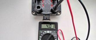
Inductive-type rotation sensors are checked by measuring their resistance (usually 0.2...0.9 Kom - see database). It is convenient to check Hall sensors with an LED probe. Other sensors play a secondary role compared to rotation sensors, so here we will only say that, to a first approximation, their serviceability can be checked by monitoring the change in voltage on the signal wire following a change in the parameter that the sensor measures. If the measured value changes, but the voltage at the sensor output does not, it is faulty. Many sensors are tested by measuring their electrical resistance and comparing it with a standard value (see bases). Checking execution functions.
ECU execution functions include:
— main relay control;
— control of the fuel pump relay;
— ignition control;
— nozzle control;
— control of the idle speed stimulator (IDLE ACTUATOR - sometimes it’s just a valve);
— control of additional relays;
— lambda regulation;
— management of additional devices;
Control of the main relay, if its operation as a supporting function has been checked, can be established by measuring the voltage at the ECU connector pin to which this relay supplies voltage (i.e., by consequence). The specified voltage should appear after turning on the ignition. Of course, such a check assumes the integrity of the wiring. Another way to check is with a low-power test lamp (no more than 1 W), connected between +12V and the ECU control contact. Please note: the lamp must be fully illuminated after the ignition is turned on. Checking the control of the fuel pump relay should take into account the logic of the fuel pump. On some vehicles, the winding of this relay is powered from the main relay contact.
In practice, the entire ECU-relay-fuel pump channel is often checked by the characteristic buzzing sound of preliminary fuel pumping within 1...3 seconds after turning on the ignition. However, not all cars have such pumping, which is explained by the developer’s approach: it is believed that the absence of pumping has a beneficial effect on engine mechanics due to the advanced start of the oil pump. In this case, you can use a test lamp (power up to 1 W), as was described in checking the control of the main relay (adjusted for the logic of the fuel pump). This technique is more correct, because, for example, if there is initial pumping, then the fuel pump will not necessarily work when you try to start the engine. The fact is that the ECU can contain up to three functions for controlling the fuel pump relay “on one wire”. In addition to pumping, there may be a function to turn on the fuel pump based on the starter activation signal (“50”), as well as based on the signal from the rotation sensors. Accordingly, each of the three functions depends on its support, which actually forces them to be distinguished.
Note that breaking the fuel pump relay control circuit is a common method of blocking for anti-theft purposes and is used in a number of security systems. For safety reasons, some car models use an automatic fuel pump wiring disconnector (located in the trunk), which is triggered by impact. To restore the operation of the fuel pump, you need to manually reset the breaker. Ignition control is usually checked by the consequence - the presence of a spark. This can be done using a known-good spark plug, connecting it to a high-voltage wire removed from the engine spark plug (it is convenient to place the test plug in the mounting ear of the engine). To avoid damage to the coil, switch or controller, do not check the spark from the high-voltage wire to ground without a connected spark plug! If there is no spark, you should check the presence of supply voltage on the ignition coil (“15” wire on the wiring diagram) and control pulses coming to “1” contact of the coil from the ECU or switch. The presence of pulses on the coil should be checked using a test lamp, and on an ECU working with a switch, using a pulse indicator (not to be confused with an LED probe) or an oscilloscope when the engine is rotated by the starter. Note that a faulty switch can block the operation of the ECU, so the test can be carried out with the switch disconnected - using a pulse indicator (an oscilloscope is often not applicable in this case). The operation of the injectors begins to be checked by measuring the voltage on their common power wire with the ignition on - it should be close to the voltage on the battery. Sometimes this voltage is supplied by the fuel pump relay, in which case the logic of its appearance repeats the logic of the operation of the fuel pump of a given vehicle. The integrity of the injector winding can be checked with a tester (databases provide information on nominal resistances).
You can check the presence of control pulses using an LED probe, or more correctly, a 12V low-power light bulb, connected instead (or in parallel) to any of the injectors. When the starter is turned on, the probe should flash. However, if there is no voltage on the common power wire of the injectors, such a test will not show pulses, even if they exist. Then you should switch from this wire to the “+” of the battery - the probe will show pulses, if any (we assume that the control wire is intact). It should be borne in mind that there are malfunctions (ECU) when, as a result of the presence of a constant minus (instead of periodic control pulses), the injectors remain open all the time, and when the gas pump is running, so much gasoline is poured in that, during long-term attempts to start, the engine mechanics can be damaged . Check whether the oil level is increasing (due to the fact that gasoline flows through the cut in the piston rings into the engine crankcase).
When checking control pulses on coils and injectors, it is important to monitor the situation when pulses are present, but within their duration the load does not switch directly to ground. There are cases (ECU malfunctions) when switching occurs through the resistance that appears. This will be indicated by a relatively reduced brightness of the flashes of the control lamp or a non-zero potential of the control pulse (checked with an oscilloscope). The lack of control of at least one injector or coil, as well as a non-zero potential of control pulses, will lead to uneven operation of the engine, it will shake. The operation of the starting injector is checked in exactly the same way. The condition of a cold engine can be simulated by opening the connector of the coolant temperature sensor (hereinafter referred to as engine temperature for brevity). An ECU with such an open input will take a temperature of approximately -40 degrees. Celsius. The idle speed booster control, if it is just a valve, can be checked by hearing its characteristic buzzing sound when the ignition is turned on. A hand placed on the valve will feel a vibration.
If this does not happen, you should check the resistance of its winding (windings, if it is three-wire). Typically, the winding resistance ranges from 4 to 40 ohms (see databases). A common malfunction of the idle air valve is its contamination and, as a result, complete or partial jamming of the moving part. It can be checked using a special device (pulse width generator), which allows you to smoothly change the current value and, thus, visually observe the smoothness of its opening and closing on the removed valve. If the valve jams, it must be washed with a special cleaner, and in field conditions it can be used with acetone or solvent. Note that a malfunctioning idle air valve is the cause of difficulty starting a cold engine. A case worth mentioning is that, according to all electrical checks, the idle valve. looked serviceable, but unsatisfactory x.x. was called by him. In our opinion, this can be explained by the sensitivity of some control systems to weakening of the valve return coil spring due to aging of the spring metal.
All other idle speed drivers are checked with an oscilloscope using sample diagrams from the databases. When carrying out measurements, the exciter connector must be connected, because otherwise, there may be no generation at the corresponding unloaded ECU outputs. Oscillograms are observed by changing the crankshaft speed. Note that throttle positioners, designed as a stepper motor (with a rod) and playing the role of an idle speed stimulator (for example, in mono injection) tend to become unusable after long periods of inactivity. Don't buy them on sale! A number of engine control systems are particularly sensitive to idle programming. This refers to systems that, without being programmed for idle speed, prevent the engine from starting. For example, the engine may start relatively easily, but without accelerating it will immediately stop (not to be confused with blocking by a standard immobilizer). Or cold starting of the engine will be difficult, and there will be no normal idle. The first situation is typical for self-programming systems with given initial settings. It is enough to maintain engine speed with the accelerator for 7...10 minutes, and i.e. will appear. After the next complete shutdown of the ECU, for example, when replacing the battery, its programming will be required again. The second situation is typical for ECUs that require initial parameters to be set by a service device. The specified settings are saved during subsequent complete shutdowns of the ECU, but are lost if the idle booster connector is disconnected while the engine is running. This is where the list of basic engine electrical checks actually ends. Checking execution functions II.
As can be seen from the text above, the motivators is no longer decisive for starting the engine (remember, it was conventionally assumed that the starter was working, but the engine did not start). However, issues of operation of additional devices and relays, as well as lambda regulation, sometimes cause no less difficulties in diagnostics and, accordingly, also sometimes lead to incorrect rejection of the ECU. Therefore, in this regard, we will briefly highlight important points that are common to the vast majority of engine control systems. Here are the main points that you need to know so that the logic of operation of additional engine equipment becomes clear:
— the gas tank ventilation system is designed to remove vapors intensively generated due to heating of gasoline pumped through a hot injector ramp. These vapors are discharged into the power supply system, and not into the atmosphere for environmental reasons. The ECU meters the fuel supply taking into account the vaporous gasoline entering the engine intake manifold through the gas tank vent valve.
— the exhaust gas recirculation system is designed to reduce the combustion temperature of the mixture and, as a result, reduce the formation of nitrogen oxides.
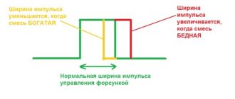
— lambda regulation acts as exhaust feedback so that the ECU “sees” the result of fuel dosing. The lambda probe or, otherwise, the oxygen sensor operates at a temperature of the sensitive element of about 350 degrees. Celsius and reacts to residual oxygen in the exhaust gases (by changing the voltage on its signal wire). If the mixture is lean, the sensor output has a low potential (about 0V); if the mixture is rich, the sensor output has a high potential (about 1V).
Control of additional relays
The control of additional relays can be checked in virtually the same way as the control of the main relays (see above), you just need to pay attention to the logic of their operation. Thus, the intake manifold heating relay is activated only on a cold engine, which can be simulated, for example, by inserting a potentiometer with a nominal value of about 10 Kom into the connector of the engine temperature sensor instead of this sensor. Rotating the potentiometer knob from high to low resistances will simulate engine warming up. Accordingly, first the heating relay should turn on (if the ignition is on), then turn off. Lack of heating of the intake manifold on a cold engine can cause difficult starting. The radiator cooling fan relay turns on the opposite way - when the engine is hot. A two-channel control design is possible - based on airflow at different speeds. It is checked in exactly the same way using a potentiometer connected to the engine temperature sensor connector (not to be confused with the temperature sensor for the indicator on the instrument panel). The ECU output is checked with a low power test lamp (see above). Note that only a small group of European cars have control of the specified relay from the ECU. The lambda probe heating relay ensures that the heating element of this sensor is turned on. The relay is triggered by signals from rotation sensors, i.e. when starting the engine, and remains on until the engine stops. Often, this relay is controlled not from the ECU, but from one of the main relays or simply from the ignition switch, or is absent altogether - then the lambda probe heater is turned on by one of the main relays, which makes it necessary to take into account their operating logic. Note that the term “phase change relay” found in the literature means nothing more than a lambda probe heating relay. Lack of heating of the lambda probe leads to unstable, uneven operation of the engine at idle and loss of throttle response when driving.
To troubleshoot an injection engine, use the equipment on our website at the following link:

