Smoke from the exhaust pipes of a diesel truck when the engine is started
Exhaust gases
(exhaust gases) - working fluid spent in the engine. They are products of oxidation and incomplete combustion of hydrocarbon fuels. Exhaust gas emissions are the main reason for exceeding permissible concentrations of toxic substances and carcinogens in the atmosphere of large cities and the formation of smog, which is a common cause of poisoning in confined spaces.
The amount of pollutants released into the atmosphere by cars is determined by the mass emission of gases and the composition of the exhaust gases.
Car exhaust gas quantity
Mainly determined by the mass fuel consumption of cars. Distance consumption is standardized and usually indicated by manufacturers (one of the consumer characteristics). In relation to the total volume of exhaust gases coming out of the muffler, we can approximately focus on the following figure - one kilogram of burned gasoline leads to the formation of approximately 16 kilograms of a mixture of various gases.
| VAZ 2110 1.5k liter | VAZ 2110 1.5i liter | Mitsubishi Colt 5-D 1.1i liter | VAZ 11113 0.75k liters | VAZ 21055 1.5D liter | |
| Consumption in “urban” mode, l/100km | 9,1 | 8,6 | 7,0 | 6,4 | 5,7 |
| Consumption, uniformly 60 km/h, l/100km | 6,5 | 6,5 | 3,7 | 3,2 | 3,8 |
- k - carburetor engine
- i - injection engine
- D - diesel engine
- The density of gasoline at +20C ranges from 0.69 to 0.81 g/cm³
- density of diesel fuel at +20C according to GOST 305-82 no more than 0.86 g/cm³
Composition of automobile exhaust gases
| Gasoline engines | Diesels | |
| N2, vol.% | 74—77 | 76—78 |
| O2, vol.% | 0,3—8,0 | 2,0—18,0 |
| H2O (vapour), vol.% | 3,0—5,5 | 0,5—4,0 |
| CO2, vol.% | 0,0—16,0 | 1,0—10,0 |
| *, about.% | 0,1—5,0 | 0,01—0,5 |
| Nitrogen oxides*, vol.% | 0,0—0,8 | 0,0002—0,5 |
| Hydrocarbons*, vol.% | 0,2—3,0 | 0,09—0,5 |
| Aldehydes*, vol.% | 0,0—0,2 | 0,001—0,009 |
| Soot**, g/m3 | 0,0—0,04 | 0,01—1,10 |
| Benzpyrene-3.4**, g/m3 | 10—20·10−6 | 10×10−6 |
* Toxic components
**Carcinogens
Methods for neutralizing exhaust gases in the exhaust system
Exhaust gas neutralization systems in the exhaust system of internal combustion engines Read more: Neutralization of exhaust gases in the exhaust system of diesel engines
1. Methods for neutralizing exhaust gases in the exhaust system
There are several ways to neutralize exhaust gases in the exhaust system of a car:
1. Oxidation of exhaust gases by supplying additional air to them in thermal reactors. Thermal reactors are installed on many Japanese and American engines. A thermal reactor is a thermally insulated volume with a special organization of the flow of exhaust gases, installed in the exhaust system of the engine and carrying out thermal oxidation of toxic components using the own heat of the exhaust gases. Thermal neutralization does not depend on the type of fuel burned, the presence of additives and allows the use of leaded gasoline in engines. It is possible to increase the temperature of the exhaust gases in the reactor by reducing heat loss by using spacers-screens, thermal insulation of the reactor vessel, using the heat of the oxidation reaction, as well as a short-term decrease in the ignition timing. The reactors are especially effective in rich mixture modes at high loads, do not fail over time, but do not completely oxidize CO and CH and do not reduce NOx, therefore they are used as additional devices in front of the catalytic converter.
2. Absorption of toxic components by liquid in liquid neutralizers. This method is not widely used due to its low efficiency and the need for frequent fluid replacement.
3.The use of catalytic converters and particulate filters (on cars with diesel engines) is currently the most relevant.
2. Neutralization of exhaust gases in the exhaust system of gasoline engines
The evolution of catalytic converters
At the end of the 60s, when the megacities of America and Japan began to literally suffocate from smog, government commissions took the initiative. It was the legislation on the mandatory reduction of toxic emissions from new cars that forced industrialists to improve engines and develop neutralization systems.
In 1970, the United States passed a law requiring that 1975 model year vehicles have emissions levels that are, on average, half those of 1960 models: 87% CH, 82% CO, and 82% NOx. by 24%.
Similar requirements have been legalized in Japan and Europe. First of all, engineers rushed to improve the power supply and ignition systems. But it was obvious that it was simply impossible to achieve such a significant improvement in the toxicity situation without the use of additional devices.
In 1975, the first exhaust gas catalytic converters appeared on American cars - then still two-component, the so-called oxidative type. They were called two-component because they could neutralize only two toxic components - CO and CH. Oxidative - because the reactions that took place were the oxidation (that is, actually the afterburning) of CO and CH molecules with the formation of carbon dioxide CO2 and water H2O.
On American cars in 1975, transistor ignition systems with high spark energy and spark plugs with a copper core of the central electrode appeared - this minimized misfires and subsequent flashes of unburned fuel in the converter, which threaten to melt the ceramics.
In 1977, an “anti-nitrogen” section was added to it, and a couple of years later they combined everything into a single housing, giving the incorrect name “three-stage” neutralizer. In fact, we are not talking about steps, but about three suppressed classes of harmful substances.
By 1990, the converter moved close to the exhaust manifold in order to quickly heat up to operating temperatures (300ºС) - thereby reducing harmful emissions during the warm-up stage.
In 1995, Emitek developed a technology for heating the catalyst with powerful electrical resistance. The “6C” (or “Emicat”) catalyst model based on this principle was installed on the BMW Alpina B12.
And finally, in 2000, a zeolite trap for hydrocarbons (CH) appeared, trapping them when the engine starts and only after heating to 220°C is it “eaten up” by the ready-to-use catalyst.
Design and principle of operation of catalytic converters
Modern catalytic converters are three-way catalytic converters.
The three-way catalytic converter is a stainless steel housing that is integrated into the exhaust system before the muffler. The housing contains a carrier block with numerous longitudinal pores, coated with a thin layer of catalyst substance, which itself does not enter into chemical reactions, but by its very presence accelerates their flow.
Chemists know many catalysts - copper, chromium, nickel, palladium, rhodium. But noble platinum turned out to be the most resistant to the effects of sulfur compounds that are formed during the combustion of the sulfur contained in gasoline. Catalysts account for up to 60% of the cost of the device. It is thanks to them that the necessary chemical reactions occur - the oxidation of carbon monoxide (CO) and unburned hydrocarbons (CH), as well as the reduction of the amount of nitrogen oxide (NOx). In a three-component neutralizer, platinum and palladium cause the oxidation of CO and CH, and rhodium “fights” NOx. By the way, rhodium, a by-product in the production of platinum, is the most valuable of this trinity.
To increase the contact area of the catalytic layer with the exhaust gases, a substrate 20-60 microns thick with a developed microrelief is applied to the surface of the honeycomb.
As a rule, the carrier in the neutralizer is special ceramics - a monolith with many longitudinal honeycomb cells, on which a special rough substrate is applied (Fig. 1). This makes it possible to maximize the effective contact area of the catalytic coating with exhaust gases - up to about 20 thousand m2. Moreover, the weight of noble metals deposited on the substrate over this huge area is only 2-3 grams!!! The ceramics are made quite fire-resistant - can withstand temperatures up to 800-850 ºС. But still, if the power supply system malfunctions and long-term operation on an over-enriched working mixture, the monolith may not be able to withstand it and melt - and then the catalytic converter will fail. This is why the use of catalytic converters with a ceramic carrier on carburetor engines is so problematic.
However, thin metal honeycombs are increasingly being used as carriers of the catalytic layer (Fig. 2). This allows you to increase the working surface area, obtain less back pressure, speed up the heating of the catalytic converter to operating temperature and, most importantly, expand the temperature range to 1000-1050ºС. The honeycomb of the Metalit neutralizers, shown in Figure 2, is made of a thin-walled (only 0.04 mm thick, not 0.15 mm like ceramics) sheet of chromium-aluminum steel, alloyed with the rare earth metal yttrium for better adhesion of the catalytic layer. This neutralizer can withstand peak temperatures up to 1300ºС.
They do this in the West, of course, not for the use of carburetors - they are almost forgotten there. It’s just that with the advent of modern engines running on lean mixtures, the demands on catalytic converters are also increasing - they must withstand more severe conditions that ceramics can no longer handle.
A simplified reaction course in the neutralizer looks like this:
CH+O2 -> CO2+H2O; NO+CO -> N2+CO2;
CO+O2 -> CO2; NO+H2 -> N2+H2O.
As a result, toxic compounds CO, CH and NOx are oxidized or reduced to carbon dioxide CO2, nitrogen N2 and water H2O (Fig. 3).
The widespread use of neutralizers has “exploded” the world market for precious metals: 35% of consumed platinum, 45% of palladium, 90% of rhodium go into automobile exhaust systems.
Warming up the catalytic converter
At first glance, it may seem that installing a catalyst solves all environmental problems. However, the temperature at which the catalyst begins to act (activation temperature) is in the range of 250–350°C. The time required for warming up can reach several minutes and depends on the type of car, how it is used and the air temperature. A cold catalyst is practically ineffective - therefore, it is necessary to reduce the time to reach the activation temperature.
By 1995, Emitek developed a technology for heating the catalyst with powerful electrical resistance. The “6C” (or “Emicat”) catalyst model based on this principle was installed on the BMW Alpina B12. The heater is mounted on a metal support inside the catalyst (Fig. 4); its power is from 0.5 to 2, sometimes 4 kW, depending on the resistance value (from 0.05 to 0.35 Ohm). For example, a 1.5 kW element heats the catalyst to 400°C in 10 seconds.
The ESIA company took a different route and proposed a starting catalyst. It is located in a special branch of the exhaust system, has smaller dimensions than the main one and, therefore, warms up faster, after which it brings the “big brother” into working condition.
To reduce harmful emissions when starting a cold engine, a hydrocarbon adsorber built into the catalyst is sometimes also used. As soon as the operating temperature is reached, the latter are “released” and oxidized by the catalyst itself. Among such devices one can name the Adcat neutralizer from Delphi or the Puma neutralizer from Corning.
Feedback
A three-component neutralizer is most effective for a certain exhaust gas composition (Fig. 5). This means that it is necessary to very accurately maintain the composition of the combustible mixture near the so-called stoichiometric air/fuel ratio, the value of which lies within a narrow range of 14.5 - 14.7. If the combustible mixture is richer, the efficiency of neutralizing CO and CH will decrease; if it is poorer, NOX will decrease.
It was possible to maintain the stoichiometric composition of the combustible mixture in only one way - to control the mixture formation, immediately receiving information about the combustion process, that is, by organizing feedback (Fig. 6). The decision was epoch-making.
A specially designed oxygen sensor was placed in the exhaust manifold - the so-called lambda probe (in the West it is customary to denote the so-called excess air coefficient with the Greek letter λ, that is, the ratio of the stoichiometric composition of the mixture to the current one). It enters into an electrochemical reaction with hot exhaust gases and produces a signal, the level of which depends on the amount of oxygen in the exhaust.
If there is a lot of oxygen left, the mixture is too lean; if there is not enough, it is rich. And based on the results of instant analysis, which is carried out by electronics, you can quickly adjust the composition of the mixture in one direction or another. The voltage at the oxygen sensor output takes two levels. If the mixture is lean, then the low-voltage signal gives a command to enrich the fuel mixture, and vice versa.
Figure 7 shows a modern three-way catalytic converter. The second oxygen sensor is needed for the latest OBD-II on-board diagnostic systems and monitors the effectiveness of neutralization.
For the first time, three-way converters with feedback and an oxygen sensor appeared on Volvo car engines in 1977. And now all cars without exception that are sold in the markets of civilized countries are equipped with them.
Oxygen sensors
The oxygen sensor (Fig. 8) - also known as a lambda probe - is installed in the exhaust manifold so that the exhaust gases flow around the working surface of the sensor. It is a galvanic current source that changes the voltage depending on the temperature and the presence of oxygen in the exhaust pipe. Its material is usually a ceramic element based on zirconium dioxide, coated with platinum. Its design assumes that one part is connected to the outside air, and the other to the exhaust gases inside the pipe. Depending on the oxygen concentration in the exhaust gases, a signal appears at the sensor output (Fig. 9). The level of this signal can be low (0.1...0.2V) or high (0.8...0.9V). There are also sensors whose output signal varies from 0.1 to 4.9 V.
Thus, the oxygen sensor is a kind of switch that informs the injection controller about the oxygen concentration in the exhaust gases. The controller receives the signal from the lambda probe, compares it with the value stored in its memory and, if the signal differs from the optimal one for the current mode, adjusts the duration of fuel injection in one direction or another. Thus, feedback is provided to the injection controller and precise adjustment of engine operating modes to the current situation, achieving maximum fuel economy and minimizing harmful emissions.
A gasoline engine requires a mixture with a specific air-fuel ratio to operate. The ratio at which the fuel burns as completely and efficiently as possible is called stoichiometric and is 14.7:1. This means that for one part of fuel you should take 14.7 parts of air. In practice, the air-fuel ratio varies depending on engine operating conditions and mixture formation. The engine becomes uneconomical.
The excess air coefficient during engine operation is constantly changing and the range of 0.9 - 1.1 is the operating range of lambda regulation. At the same time, when the engine is warmed up to operating temperature and does not develop much power (for example, idling), it is necessary to maintain as strict a balance as possible so that the three-way catalyst can fully fulfill its purpose and reduce harmful emissions to a minimum .
Lambda probes come in one-, two-, three- and four-wire types. Single-wire and two-wire sensors were used in the very first injection systems with feedback (lambda control). A single-wire sensor has only one wire, which is the signal wire. The ground of this sensor is brought out to the housing and comes to engine ground through a threaded connection. A two-wire sensor differs from a single-wire sensor by the presence of a separate ground wire for the signal circuit. Disadvantages of such probes: the operating temperature range of the sensor starts from 300 ºС. Until this temperature is reached, the sensor does not work and does not produce a signal. Therefore, it is necessary to install this sensor as close as possible to the engine cylinders so that it is heated and flows around the hottest flow of exhaust gases. The heating process of the sensor is delayed, and this introduces a delay in the moment the feedback is turned on in the controller’s operation. In addition, using the pipe itself as a signal conductor (ground) requires applying a special conductive lubricant to the threads when installing the sensor in the exhaust pipe and increases the likelihood of failure (lack of contact) in the feedback circuit.
Three- and four-wire lambda probes do not have these disadvantages. A special heating element has been added to the three-wire oxygen sensor, which is usually always on when the engine is running and, thereby, reduces the time it takes for the sensor to reach operating temperature. It also allows you to install the lambda probe at a distance from the exhaust manifold, next to the catalyst. However, one drawback remains - the conductive exhaust manifold and the need for conductive lubricant. The four-wire lambda probe does not have this drawback - all its wires serve their own purposes - two for heating, and two for signal ones. At the same time, you can screw it in as you please.
The service life of an oxygen sensor is usually 50 - 100 thousand km and largely depends on operating conditions, fuel quality and engine condition. Increased oil consumption, an over-enriched mixture and an incorrectly adjusted ignition timing greatly shorten the life of the lambda probe. As a rule, heated sensors last longer. The operating temperature for them is usually 315-320°C. The design of these sensors includes a heating element that has its contacts on the connector. The functionality of the heating element of such sensors can be checked with a regular ohmmeter. Their resistance usually ranges from 3 to 15 ohms.
A properly functioning lambda probe can say a lot about the condition of the engine and its systems. On some cars, using a sensor, you can quite accurately adjust the CO content in the exhaust gases. A faulty lambda probe will inevitably cause increased fuel consumption and a decrease in engine performance. It should be noted that not all malfunctions of the lambda probe are detected by the control unit, and if they are detected, the control unit switches to the injection control mode based on average parameters, which also leads to the results listed above. Therefore, it is recommended to carry out diagnostics at the slightest suspicion, and if a malfunction is detected, replace the lambda probe.
Conditions for normal operation of catalytic converters
These days, catalytic converters are spreading across countries and continents. They also reached the Russian hinterland. And here they are often met with... lead and crowbar. The reason is that for normal operation of the catalyst it is necessary to comply with conditions that are trivial by European standards. Let's see what kind of “trifles” these are.
Firstly, as you know, even accidentally filling the tank with leaded gasoline damages the catalyst. It is finally “poisoned” by lead - all that remains is to throw away the device.
Secondly, the catalyst works effectively only if the composition of the fuel mixture is strictly observed - 14.7 parts by weight of air to one part of gasoline. Any carburetor, even with an electronic control system, does not have such precision and speed to maintain the required mixture composition.
Thus, the catalyst is only effective in combination with an electronically controlled fuel injection system. A microprocessor has appeared on the car, which, by analyzing data on temperature, air flow through the manifold, revolutions, etc., and most importantly, signals coming from the catalytic converter, regulates the operation of the electromagnetic fuel injection nozzles. However, in the event of a spark plug failure, fuel supply interruptions, etc. the delicate balance of the composition of the working mixture is instantly disrupted - the catalyst loses its effectiveness, and in some cases forever. Therefore, the microprocessor controls the operation of the vehicle’s systems and components and reports malfunctions to the driver.
There is another problem - the catalytic converter copes well with nitrogen oxides only when there is little of them. The simplified picture is this: the higher the temperature in the combustion chamber, the more nitrogen oxides there are, and the higher it is, the greater the engine efficiency. A simple way out has been found to combat nitrogen oxides. We connected the exhaust manifold to the suction pipe, directing part of the exhaust gases back into the combustion chamber with a fresh working mixture, which reduces the filling of the cylinders and, consequently, power. It turns out that the neutralizer harms the engine.
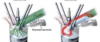
But the engine doesn’t remain in debt either. Obvious harm to the catalyst comes from the so-called valve overlap - the moment when the intake and exhaust valves are open at the same time. A draft appears, so to speak, in the cylinder: the working mixture flies out into the exhaust pipe through the open exhaust valve and poisons the sensitive catalyst. However, valve overlap helps to better fill the cylinders and increase engine power, so so far no modern engine can do without it. Here are just a few examples to show that nothing is simple in a car.
Exhaust gas neutralization systems in the exhaust system of internal combustion engines Read more: Neutralization of exhaust gases in the exhaust system of diesel engines
Information on the operation of the “Exhaust gas neutralization system in the exhaust system of the internal combustion engine”
Section: Ecology Number of characters with spaces: 40029 Number of tables: 5 Number of images: 18
Similar works
Study of the process of technical operation of fuel injectors of the distributed injection system
146575
5
12
... fuel additives, washing without dismantling the injectors using a special installation and washing on an ultrasonic stand with dismantling the injectors. 2. Study of the operation and process of technical operation of gasoline engine injectors 2.1 Design of electromagnetic injectors Let us consider the design and principle of operation of injectors using the example of a Bosch injector, as well as malfunctions that ...
Air pollution
67020
0
0
...) about 2 thousand cubic meters are released into the atmosphere. m of conventional carbon monoxide and more than 150 tons of dust. The production of cement and other building materials is also a source of dust pollution. The main technological processes of these industries - grinding and chemical processing of charges, semi-finished products and resulting products in streams of hot gases - are always accompanied by emissions of dust and...
Development of an oxidation catalyst for diesel engines
63035
16
5
...steam coming out of the muffler binds together the mechanical impurities of soot, thereby making them heavier, not allowing them to rise into the airspace. 4.2. Calculation of the consumed components for the operation of the oxidative neutralizer To carry out normal operation of the system, two main components are required that will allow the nitrogen oxidation reaction to be sufficiently complete: a) determine ...
Impact of cars on the environment
21207
0
0
... exhaust gases of carbon monoxide should contain no more than the permissible limit. The regulations on the “State Automobile Inspectorate” entrust it with monitoring the implementation of measures to protect the environment from the harmful effects of motor vehicles. The adopted toxicity standard provides for further tightening of the norm, although today in Russia they are stricter than European standards: for carbon monoxide...
The impact of exhaust gases on human health
Exhaust pipe of a passenger car
On outboard motors, exhaust gases are discharged into the water, on many models - through the propeller hub.
The greatest danger is posed by nitrogen oxides, approximately 10 times more dangerous than carbon monoxide; the share of aldehyde toxicity is relatively small and amounts to 4-5% of the total toxicity of exhaust gases . The toxicity of different hydrocarbons varies greatly. Unsaturated hydrocarbons in the presence of nitrogen dioxide are photochemically oxidized, forming toxic oxygen-containing compounds - components of smog.
The quality of afterburning on modern catalysts is such that the share of CO after the catalyst is usually less than 0.1%.
Polycyclic aromatic hydrocarbons found in gases are strong carcinogens. Among them, benzopyrene is the most studied; in addition to it, anthracene derivatives have been discovered:
- 1,2-benzanthracene
- 1,2,6,7-dibenzanthracene
- 5,10-dimethyl-1,2-benzanthracene
In addition, when using sulfur gasoline, the exhaust gases may contain sulfur oxides; when using leaded gasoline, lead (tetraethyl lead), bromine, chlorine, and their compounds. It is believed that aerosols of lead halide compounds can undergo catalytic and photochemical transformations, participating in the formation of smog.
Prolonged contact with an environment poisoned by car exhaust gases causes a general weakening of the body - immunodeficiency. In addition, gases themselves can cause various diseases. For example, respiratory failure, sinusitis, laryngotracheitis, bronchitis, bronchopneumonia, lung cancer. Exhaust gases also cause atherosclerosis of cerebral vessels. Various disorders of the cardiovascular system can also occur indirectly through pulmonary pathology. Exhaust fumes also damage the tissues of the nervous system and increase the risk of developing dementia[1].
Poisoning in confined spaces
Cases of exhaust gas poisoning are quite common, including deaths of motorists in garages, closed parking lots and inside cars (if leaked into the cabin), with poor ventilation. There have also been cases of poisoning by exhaust gases in apartments located near parking lots (inhalation of exhaust gases leads to the accumulation of toxic substances in the human body). To combat such cases, building standards for ventilation of parking lots and structures related to the operation and maintenance of vehicles are being introduced.
Ignition system
The ignition system can affect exhaust emissions in two ways:
- firstly, due to the quality of the spark produced
- secondly, by choosing the moment of spark formation
The quality of the spark will determine its ability to ignite the mixture. Spark duration is particularly important when igniting leaner mixtures. A stronger spark reduces the likelihood of misfires, which can lead to increased hydrocarbon emissions.
Rice. Effect of ignition timing on emissions and fuel consumption
It is clear that ignition timing is a critical factor and, as always, this choice is a compromise between power, vehicle performance, fuel consumption and emissions. The figure shows a graph showing the effect of ignition timing on emissions and fuel consumption. The formation of carbon monoxide depends almost exclusively on the composition of the fuel mixture and only slightly on the choice of ignition timing. Electronic and programmed ignition systems have made significant contributions towards achieving the emission levels of today's engines.
Ways to reduce emissions and toxicity
The incentive to reduce volumes is expected
interest in reducing fuel consumption (a major expense item in road transport).
- The organization of vehicle traffic
has a huge impact on the amount of emissions (not counting fuel combustion and time) (a significant portion of emissions occurs in traffic jams and in front of traffic lights [
source not specified 2249 days
]). With successful organization, it is possible to use less powerful engines at low (economical) intermediate speeds. - It is possible to significantly reduce the content of hydrocarbons in exhaust gases, by more than 2 times, by using
associated petroleum (propane, butane) or natural
gases
as fuel , despite the fact that the main disadvantage of natural gas - a low power reserve - is not so significant for the city. - In addition to the composition of the fuel, toxicity is affected by the condition and tuning of the engine
(especially diesel - soot emissions can increase up to 20 times and carburetor - nitrogen oxide emissions change up to 1.5-2 times). - Significantly reduced emissions (reduced fuel consumption) in modern designs
with injection powered by a stable stoichiometric mixture of unleaded gasoline with the installation of a converter, gas engines, units with superchargers and air coolers, and the use of a hybrid drive. However, such designs greatly increase the cost of cars. - SAE tests have shown that an effective way to reduce emissions of nitrogen oxides (up to 90%) and generally toxic gases is by injecting water into the combustion chamber
.
Selecting the moment and duration of valve opening
The effect of valve actuation timing on the exhaust composition can be quite significant. One of the main factors is the duration of valve overlap. This is the time during which the intake valve is already open, but the exhaust valve is not yet closed. The duration of this phase determines the amount of exhaust gas remaining in the cylinder when the exhaust valve finally closes. This gas has a significant influence on the reaction temperature (more exhaust gas - lower temperature), and therefore on NOx emissions. The main contradiction here is that at higher speeds, increasing the intake timing increases the power produced. On the other hand, this causes greater valve overlap at idle, which can significantly increase hydrocarbon emissions. This contradiction led to the introduction of electronic systems to control the timing and duration of valve opening.
Legislative regulation
- The quality composition
of manufactured and sold
fuel
(in Russia these are fuel standards, regional requirements, in Europe - EURO standards). - Control over the condition and adjustments
of vehicles is provided.
In Russia, it is the responsibility of the technical inspection bodies of the State Traffic Safety Inspectorate to periodically monitor the proportions of carbon oxides and hydrocarbons in the exhaust at two rotation speeds, the state of the provided neutralization systems on gasoline engines (according to GOST R 52033-2003), on gas cylinder engines (according to GOST R 17.2.02.06-1999) and smoke on diesel engines (according to GOST R 52160-2003). Two-stroke engines do not pass any of these tests [ source not specified 817 days
]. - In Russia, increased rates of transport tax on
car engine power are being introduced. - Fuel is subject to special excise taxes
. - There are standards for manufactured cars
. In Russia and European countries, EURO standards have been adopted, setting both toxicity and quantitative indicators, for example: According to Euro-3 emissions: CH up to 0.2 g/km, CO up to 2.3 g/km and NOy up to 0.15 g /km - According to Euro-4 emissions: CH up to 0.1 g/km, CO up to 1.0 g/km and NOy up to 0.08 g/km
of heavy vehicles (for example, in Moscow).
Industry Solution: Selective Catalytic Treatment
Selective catalytic reduction (SCR) of NOx with nitrogen compounds such as ammonia or urea has proven itself in industrial stationary applications. The technology was first used in thermal power plants in Japan in the late 1970s and then became widespread in Europe from the mid-1980s.
There are two forms of ammonia that can be used in SCR units: pure anhydrous ammonia and aqueous ammonia. The first variety is toxic, dangerous and requires high pressure in storage tanks and pipelines. Aqueous ammonia NH3H2O is less dangerous and easy to use. A typical industrial grade of ammonia, containing about 27% ammonia and 73% water by weight, has near-atmospheric vapor pressure at normal temperatures and can be safely circulated through industrial plant utilities.
A cost-effective alternative or smart addition: an emission filter
Diesel particulate filters (DPFs) are devices that physically capture exhaust particles and prevent them from being released into the atmosphere. Filter materials have been developed that demonstrate:
- high filtration efficiency exceeding 90%,
- resistance to mechanical damage;
- thermal stability.
Diesel particulate filters are an inexpensive but effective technology for controlling particulate emissions, including particle weight and number. The units are the optimal solution for controlling the solid fraction of hydrocarbon emissions, including elemental carbon (soot) and associated black smoke streams. Filters may have limited or no effectiveness in controlling particulate matter organic fraction (OF) and sulfate particulate matter emissions.
Standard methods such as gravity sedimentation, centrifugal separation or electrostatic capture are not used in production. The reason is the small particle size and low density of diesel soot. In conditions of serial and large-scale production, it is recommended to use catalysts for the oxidation of elements (partial filters). They can capture diesel particles and provide much higher overall efficiency than simple mechanical filters.
Due to the low bulk density of the captured components (average 0.1 g/cm3), particulate filters quickly accumulate significant volumes of soot. For comparison, an older generation truck or bus engine emits about 1 liter of soot particles. The airtight layer causes a drop in exhaust gas pressure in the filter and negatively affects engine performance.
Diesel particulate filters must be able to easily remove particulate matter from the filter bed to restore its capacity. Regeneration of the unit is carried out regularly during maintenance work or periodically, after the accumulation of soot that interferes with the normal operation of the engine.